R. Crouch, J. Oberling, B. Weaver, S. Appert
We are done with the surveying of the aLIGO BS on the mechanical test stand. I'm still working on processing the data but can give a quick overview of where things stand:
- With respect to the ISI, the BS is within the aLIGO install specifications (lateral/vertical +/- 1.0 mm; longitudinal +/- 3.0 mm)
- Position deviations when looking normal to the AR surface
- Lateral: -0.7 mm (left)
- Vertical: -0.8 mm (low)
- Longitudinal: +1.8 mm (in the +X/+Y direction)
- Will rotate these to the IFO coordinate system at a later date, once all data has been processed
- Position deviations when looking normal to the AR surface
- BS Pointing is NOT within the aLIGO install specification (Pitch +/- 55 µrad; Yaw +/- 190 µrad)
- Signs reported using the standard SUS sign convention (positive pitch is down, positive yaw is CCW when looking top-down)
- Pointing deviations from nominal (Pitch: -446 µrad; Yaw: +0.7849 rad (44.9699°) from the +Y axis)
- Pitch: -200 µrad
- Yaw: -710 µrad
- The yaw deviation appears to have been counteracted by a CCW yaw shift done via HEPI once the BS was installed in WBSC2 back in 2013; no explanation for the pitch deviation, but I do recall that pitch did not hold very well on the journey from the test stand to the chamber back in 2013, so there's no guarantee that our measured pitch here is fully representative of the BS optic pitch from in-chamber
- We have a suspiscion there is an error in the test stand monument used to do the pointing alignment back in 2013, and potentially an error in the LVEA monument used to the in-chamber pointing alignment; working out a way to test that with the FARO
- The BS SUS cage mostly hangs around the aLIGO position tolerances, but we never measured it during the 2013 install (as our target was to place the optic, and the cage ended up wherever it ended up), so this is the first data we have on its position
I'm working on a larger alog tying together all of our BS and WBSC2 measurements (WBSC2 support tube ends, BS in-chamber, and BS on the test stand) to provide a more complete picture of the BS alignment as we have measured it these last couple of weeks (it's going to be a long one); this alog will have the full set of data from the various test stand measurements. In addition, the SUS and IAS teams met yesterday to discuss our path forward. We decided that, despite the error seen in pointing on the test stand, we will align the BBS to its nominal position and pointing w.r.t. the ISI on the test stand. Once back in-chamber we will use the BBS SUS cage position as the metric for adjusting HEPI to once again place the BBS in its nominal in-chamber position; pointing will be restored with the BS optical lever, as originally planned. I'll write up a RODA documenting this decision and upload it to the DCC ASAP.
This completes LHO WP 13210.
Edit: Some spelling and grammar clean up.


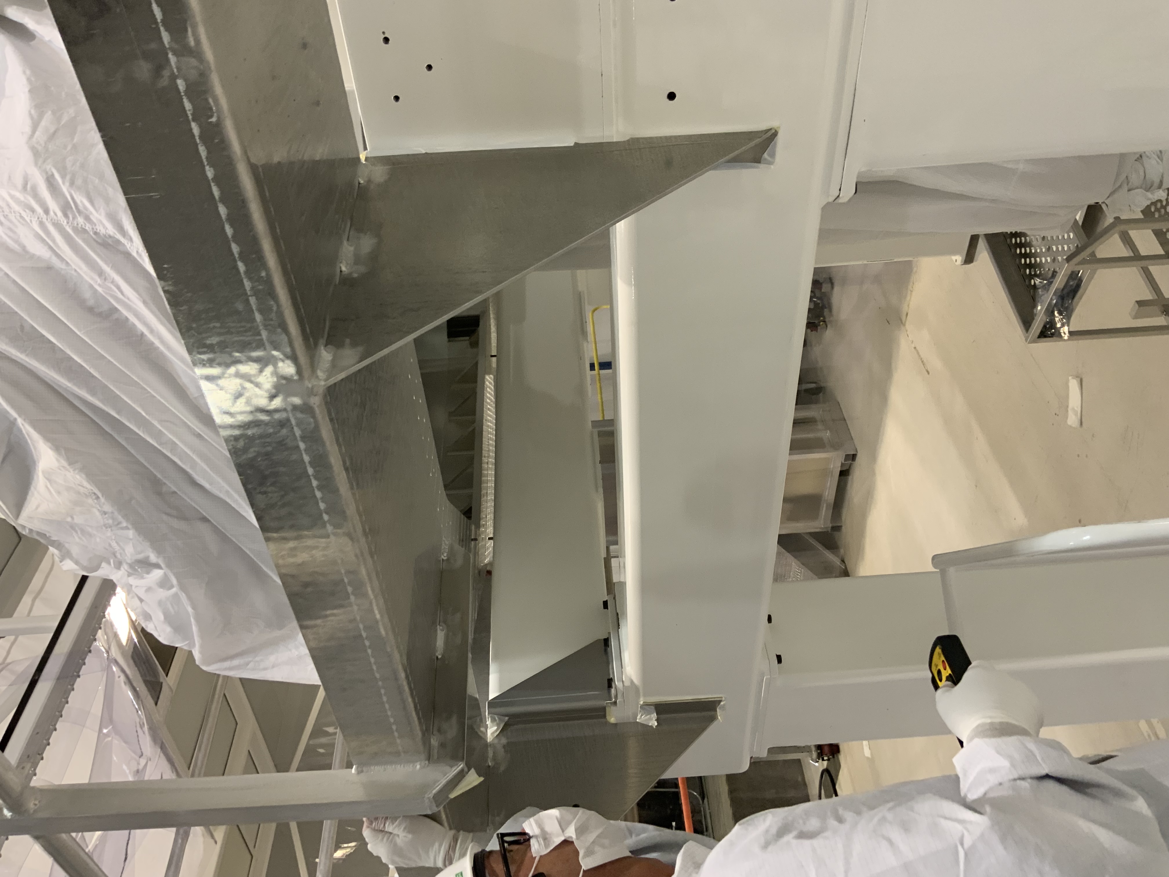
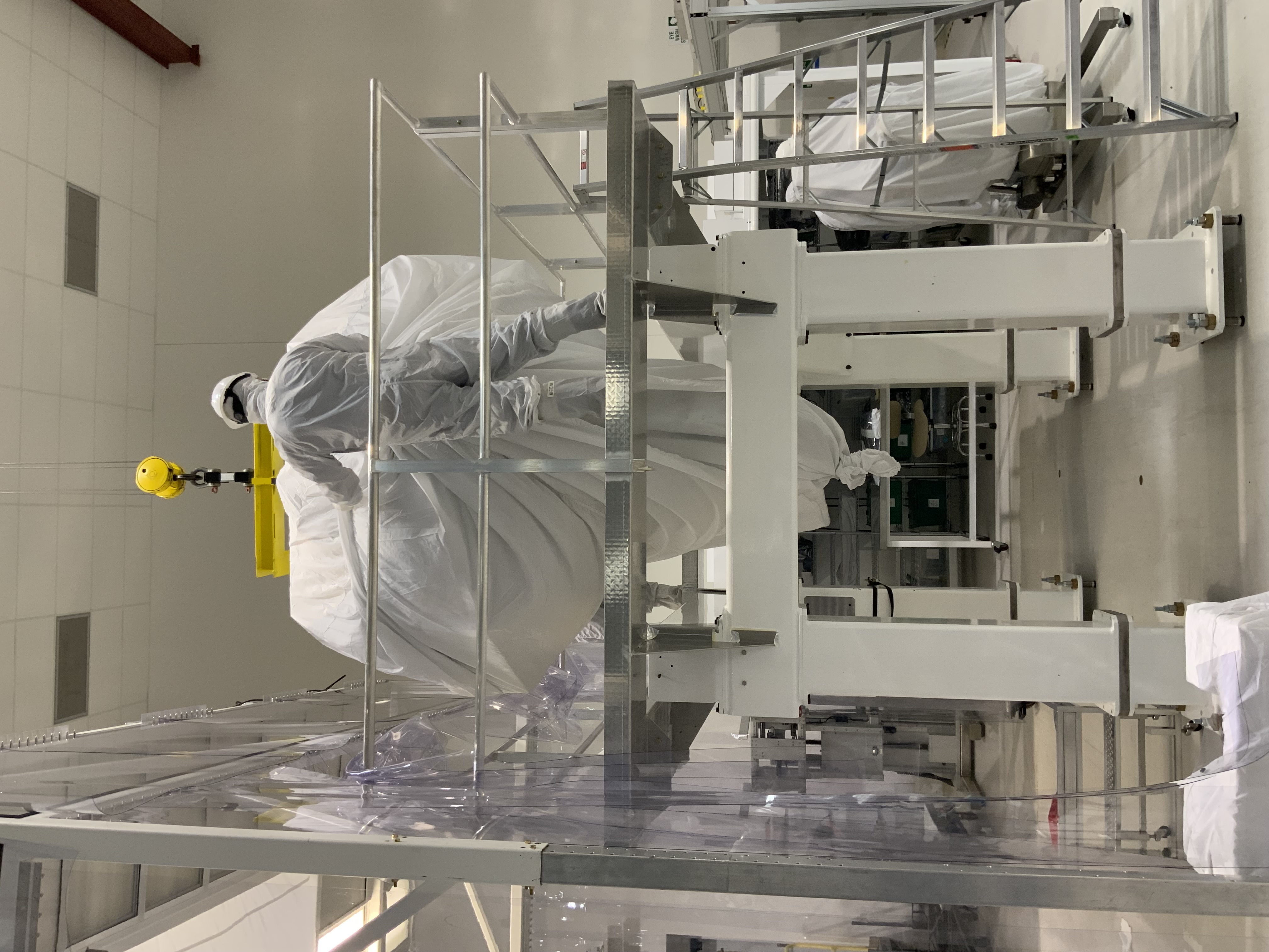
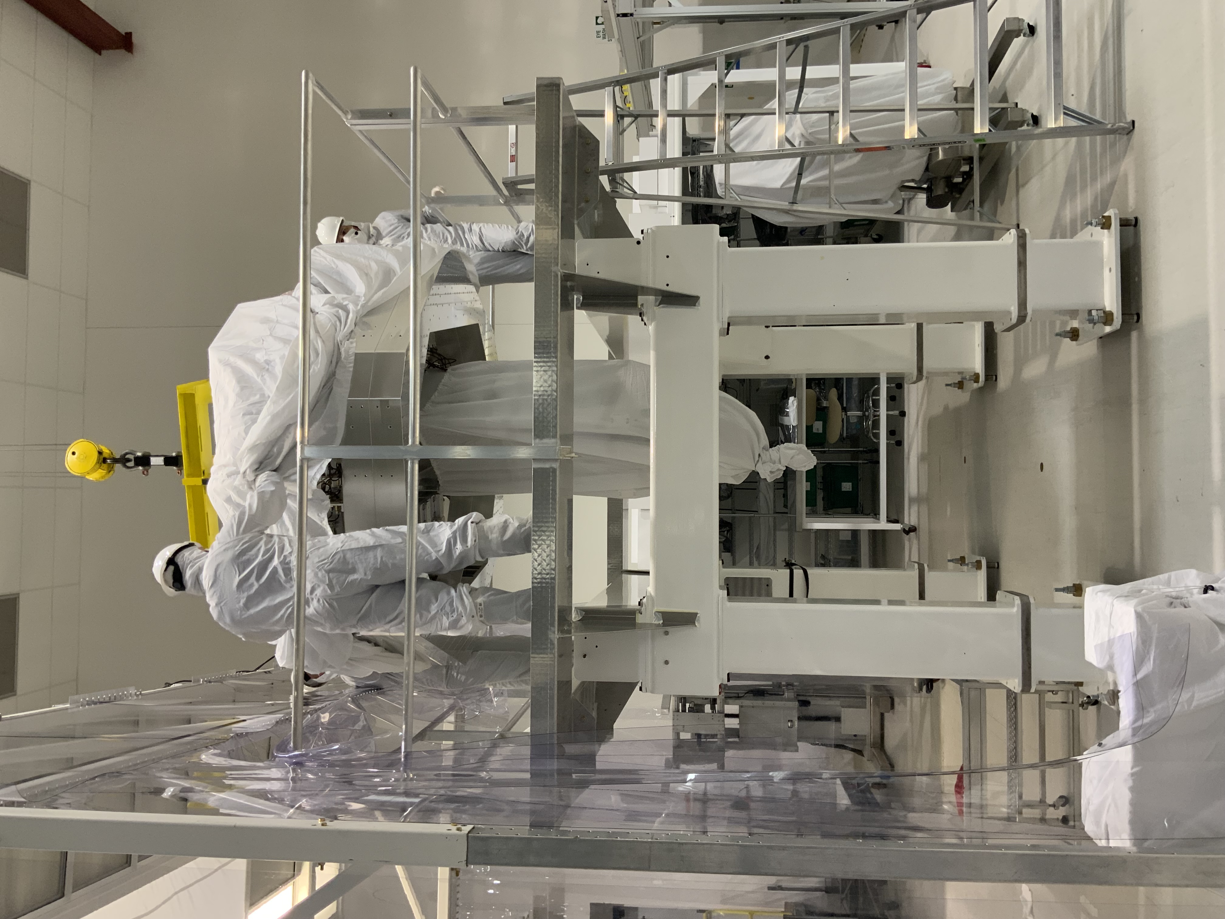
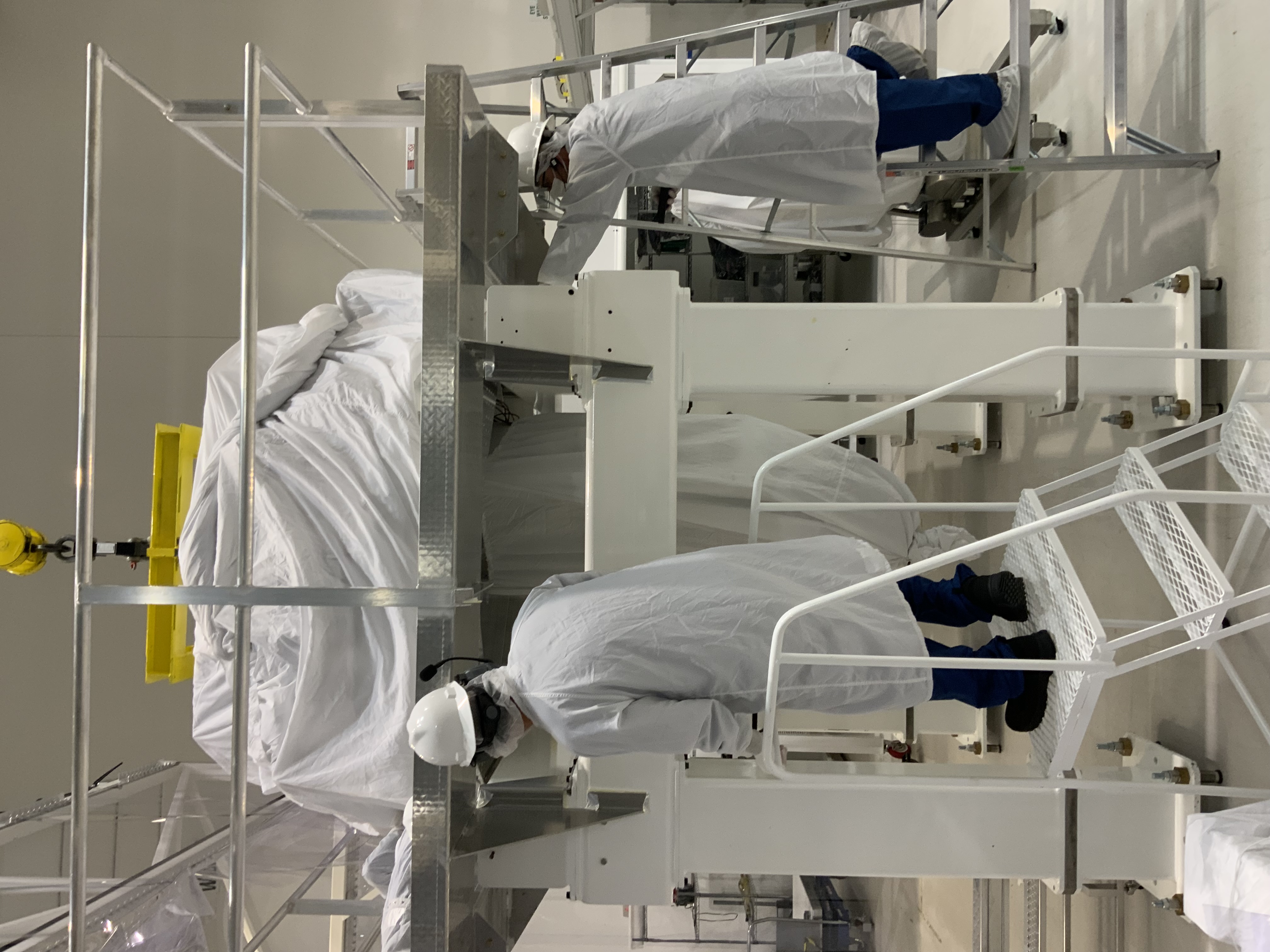
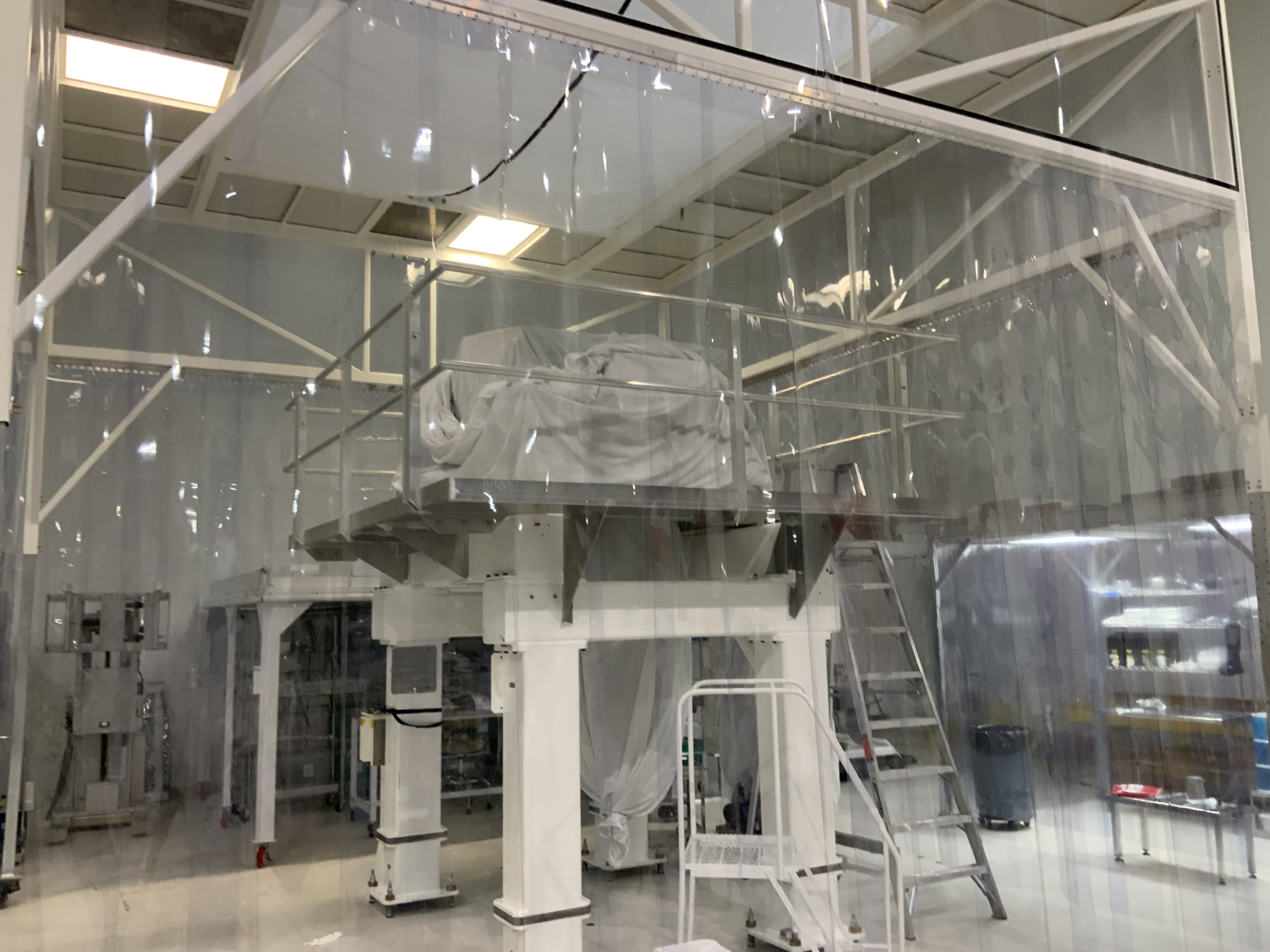
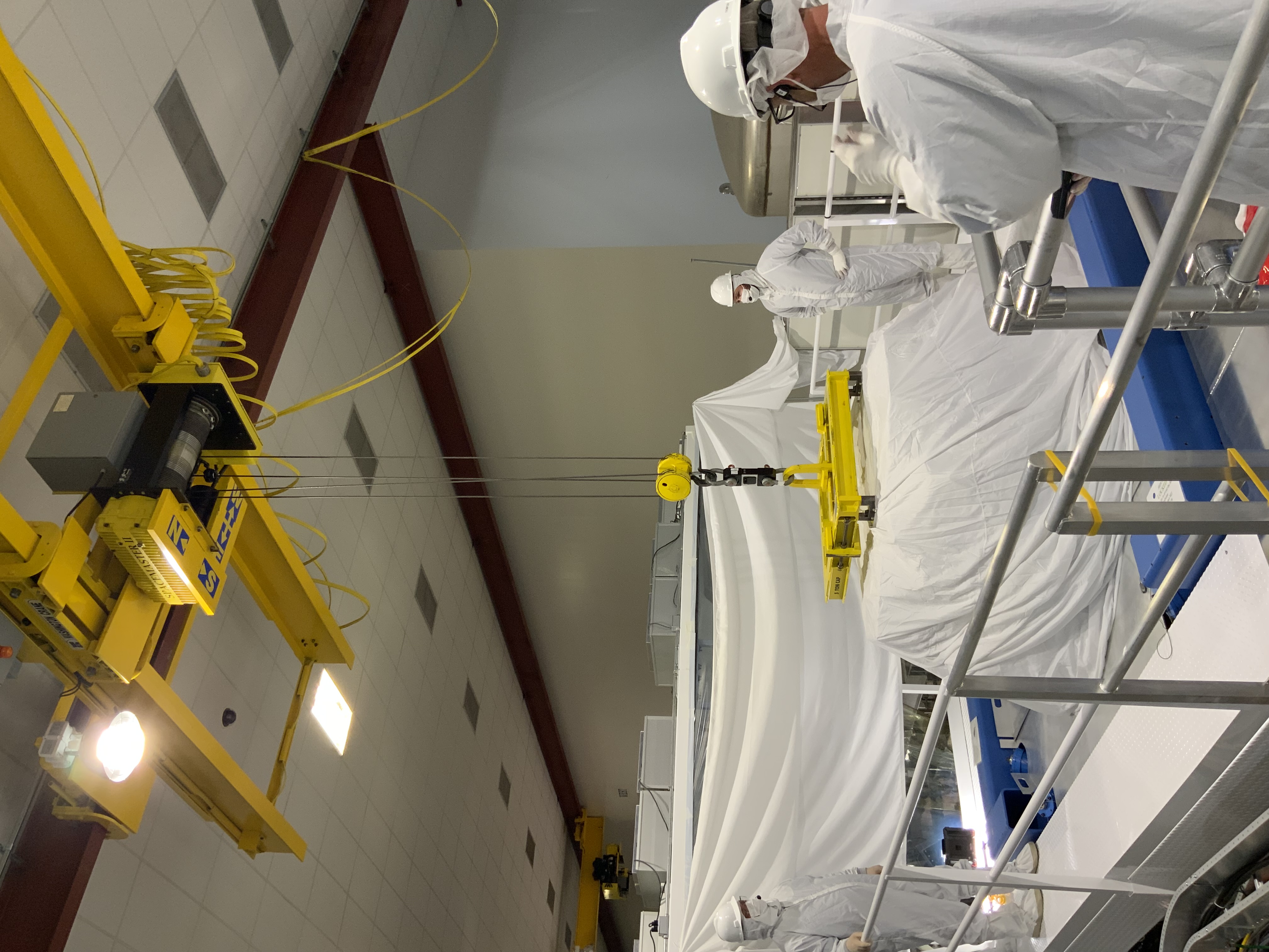
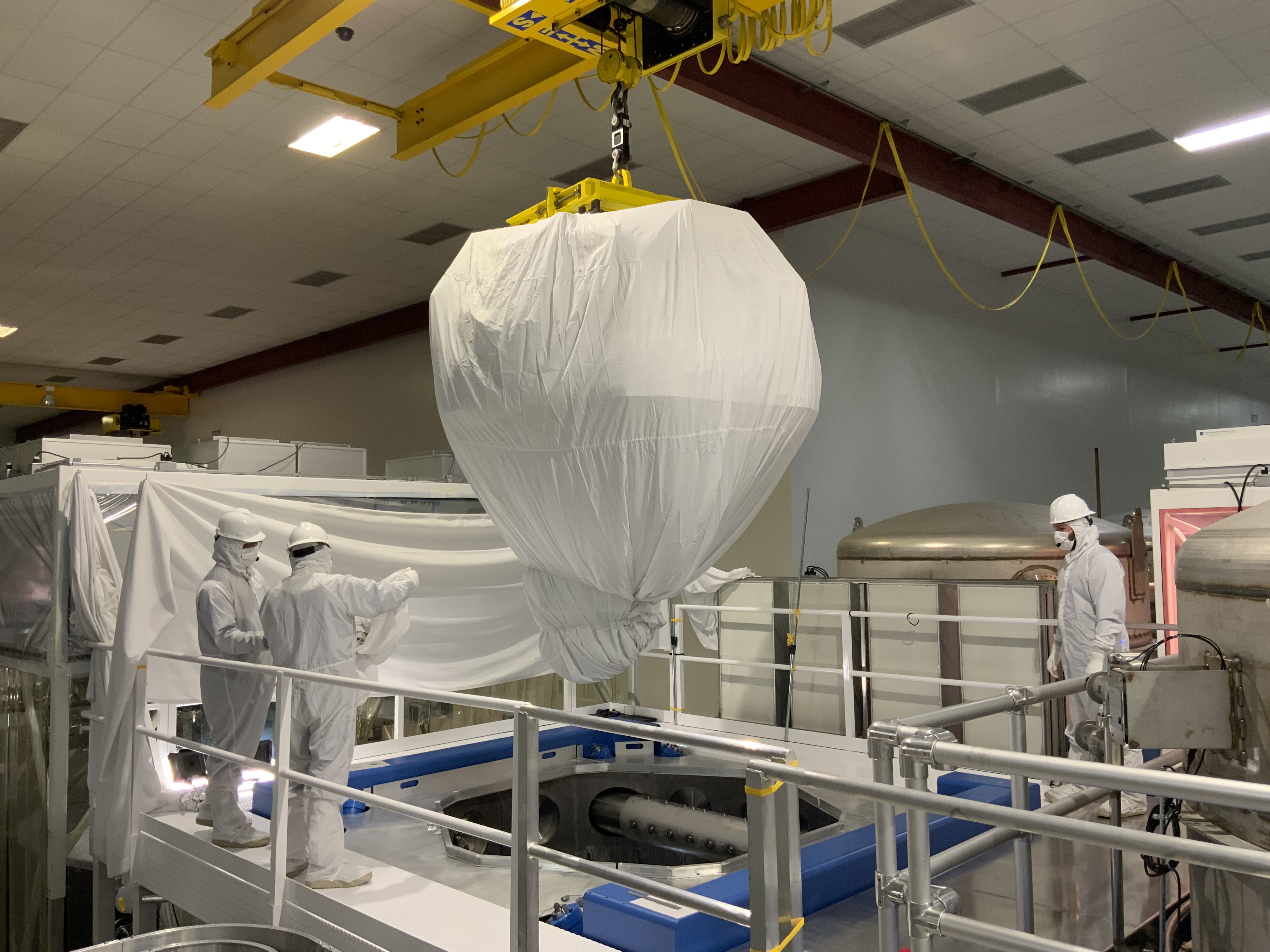
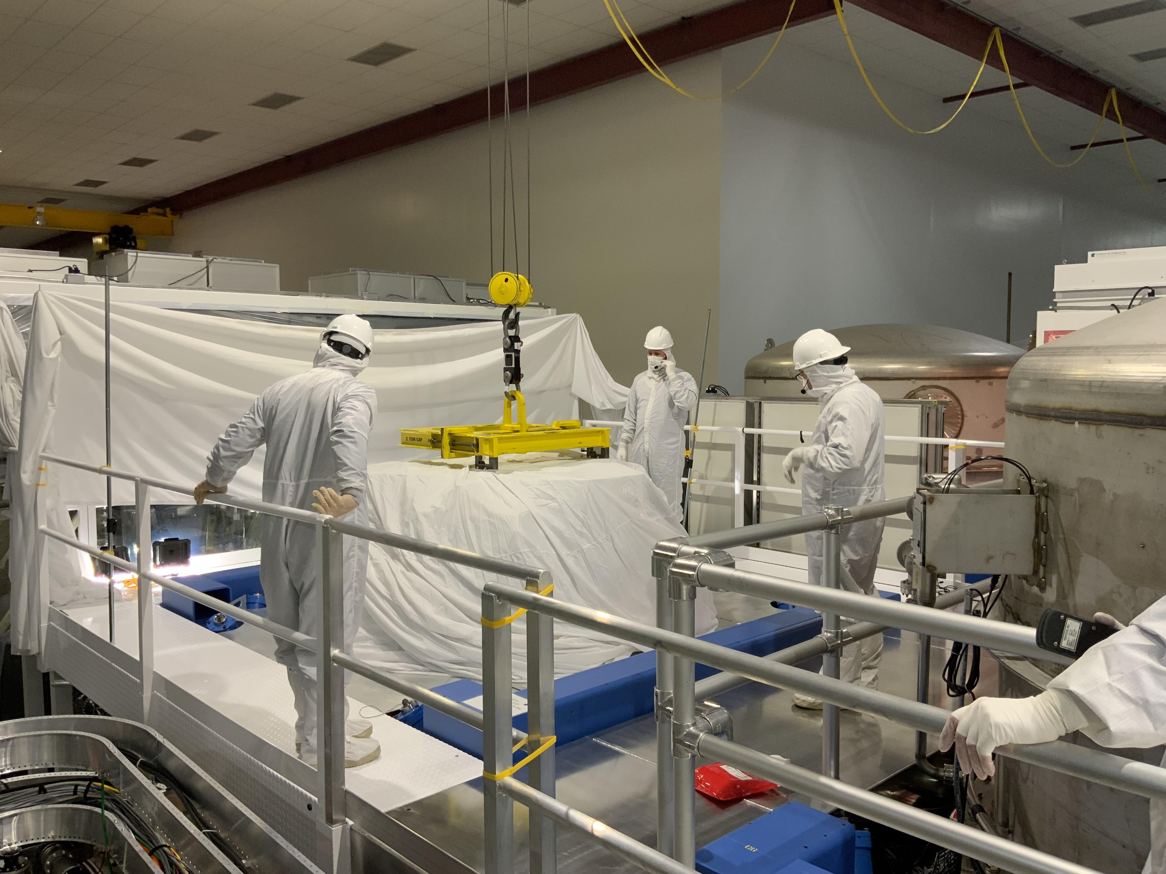
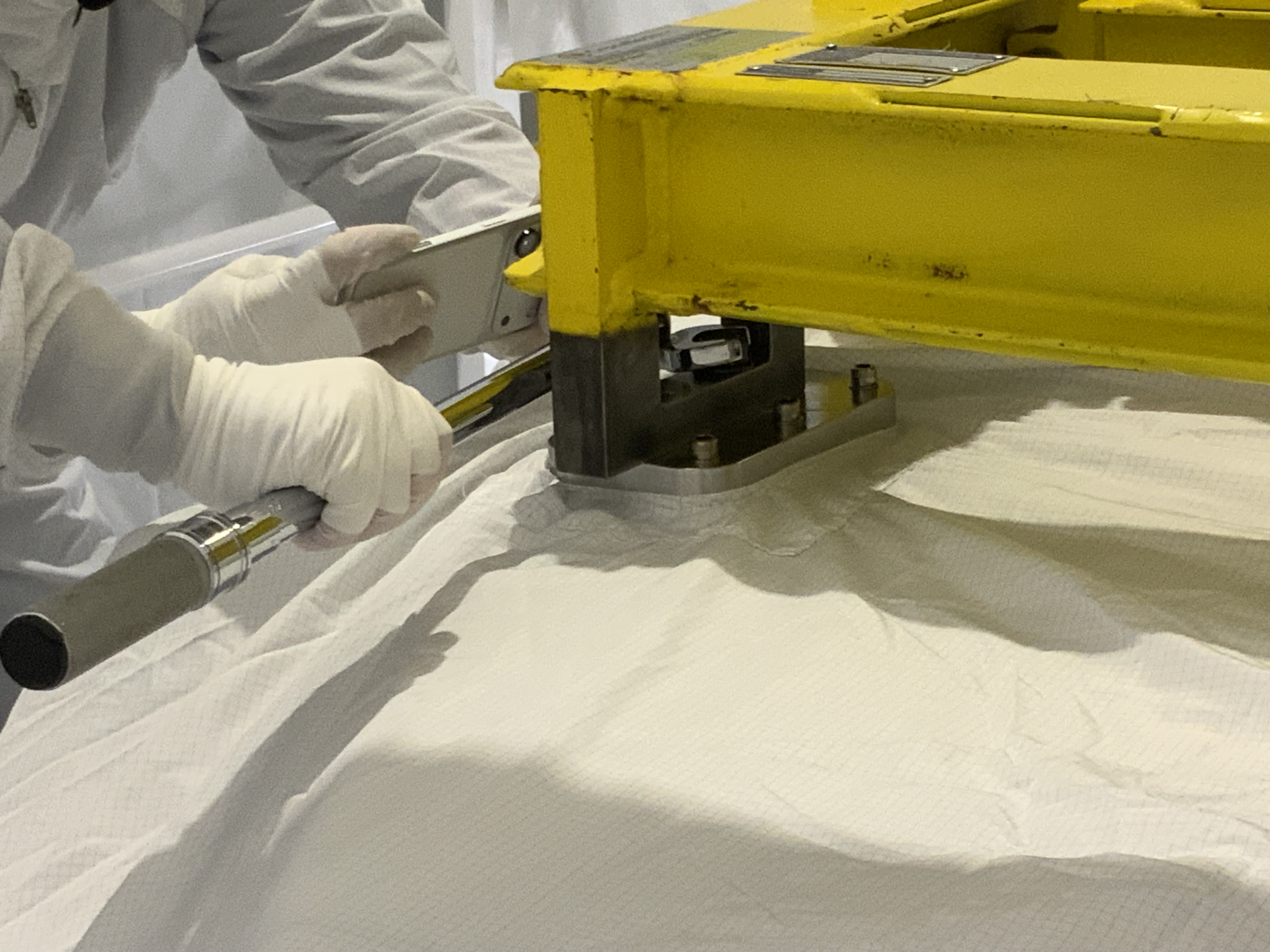
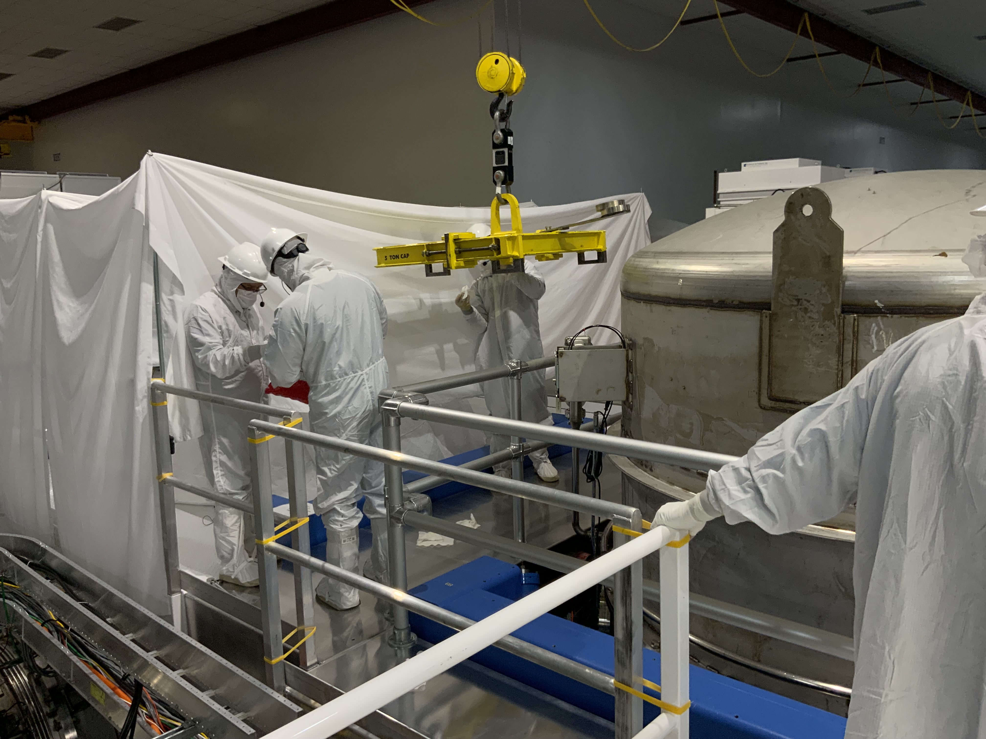
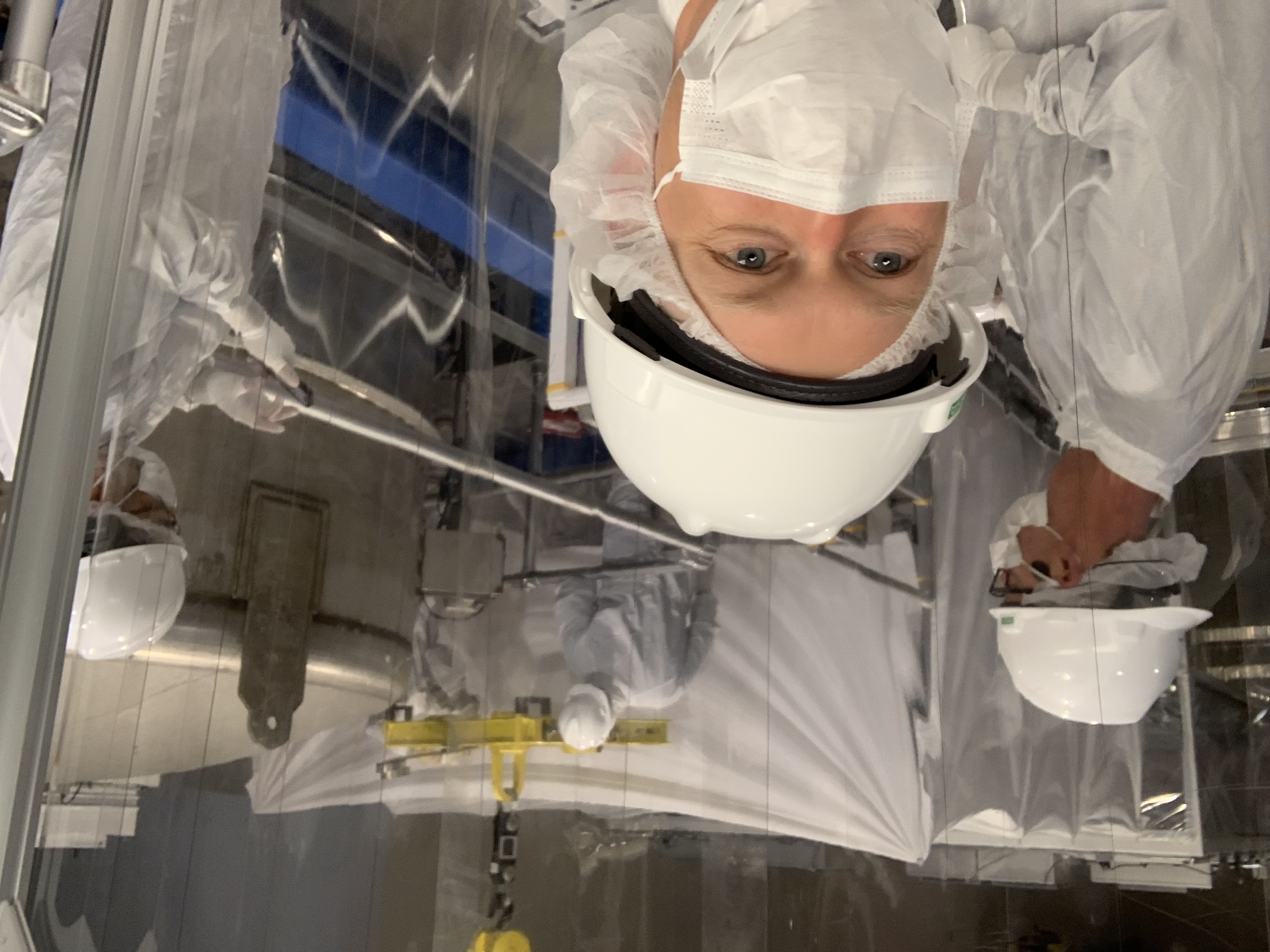
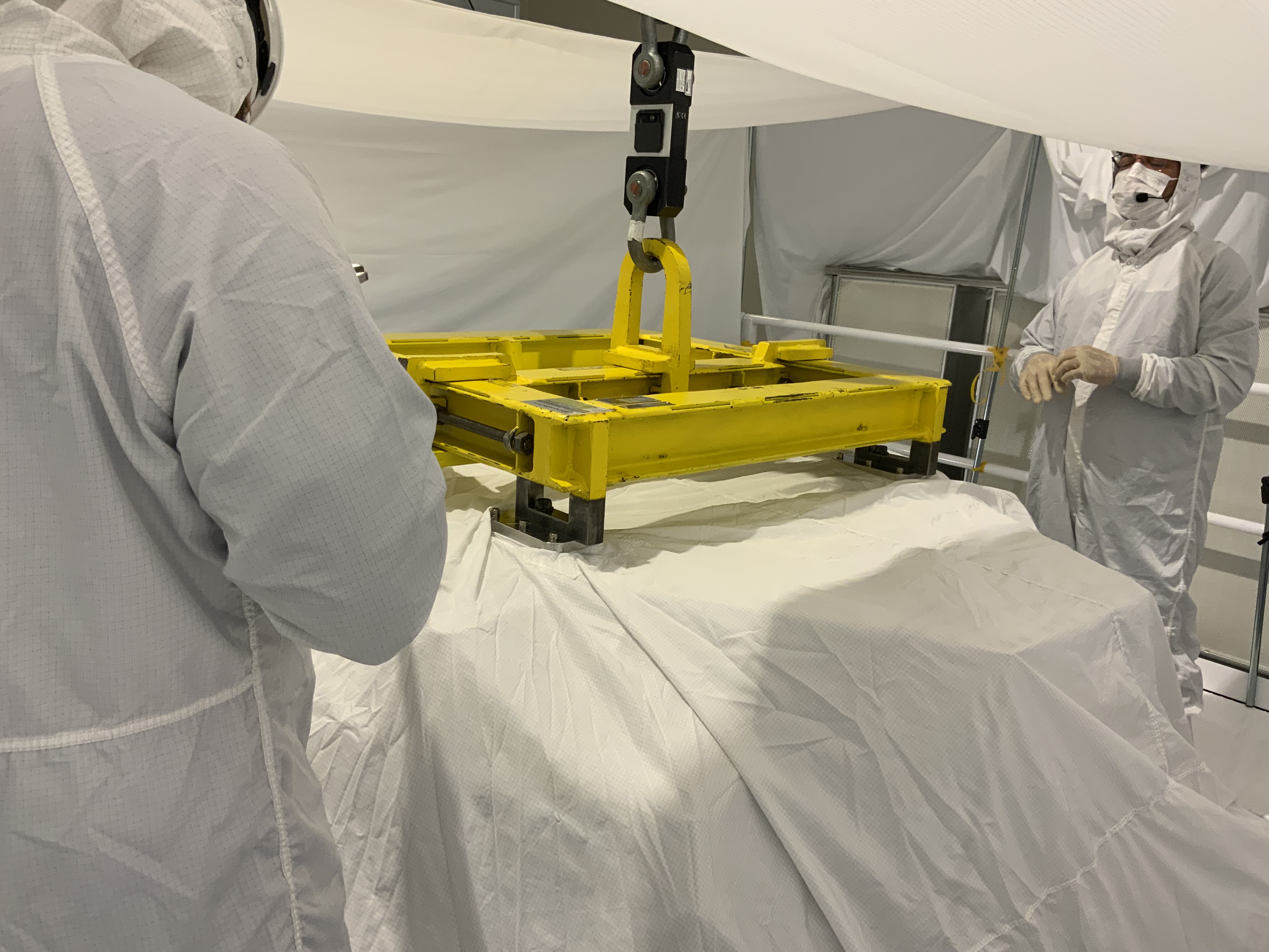
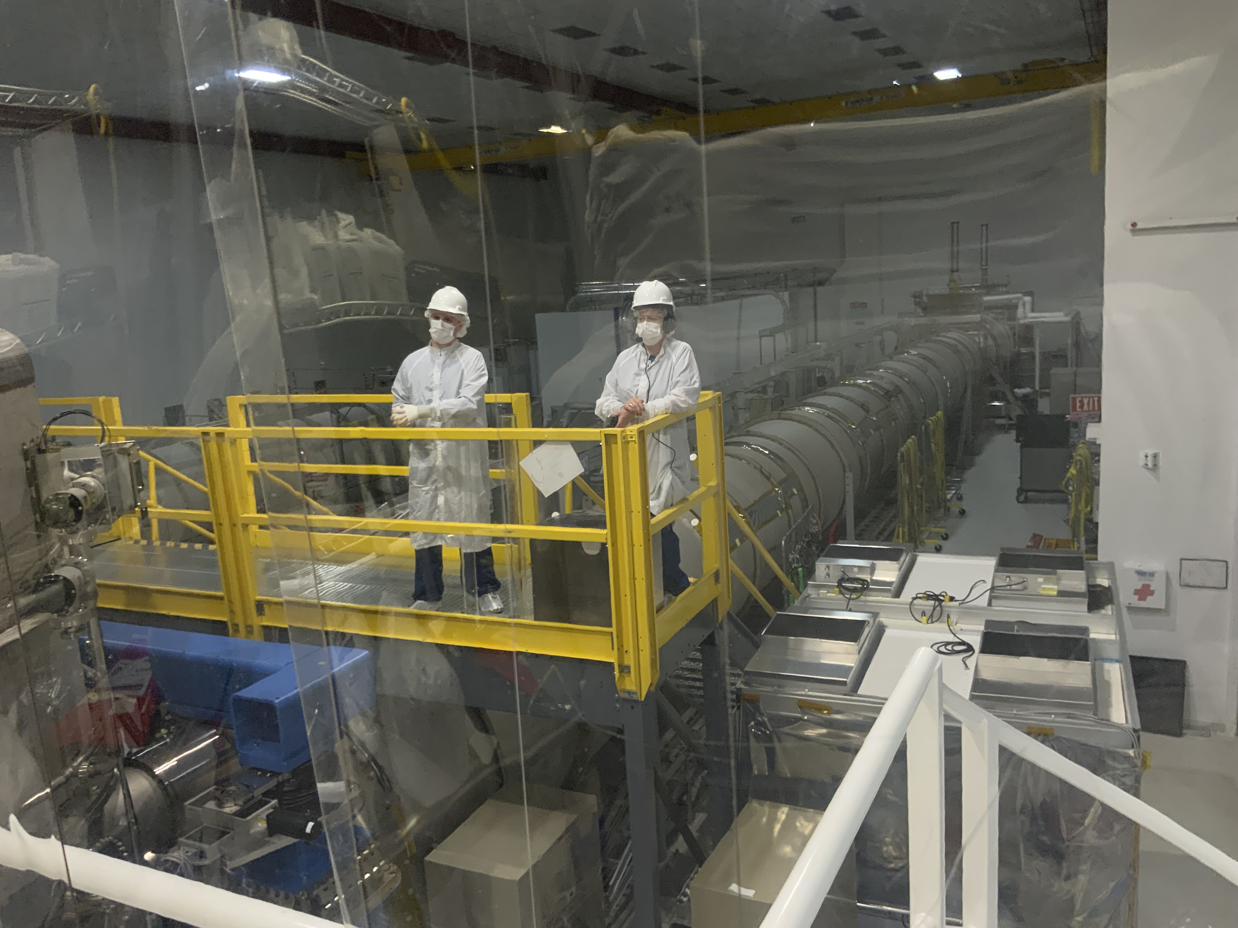
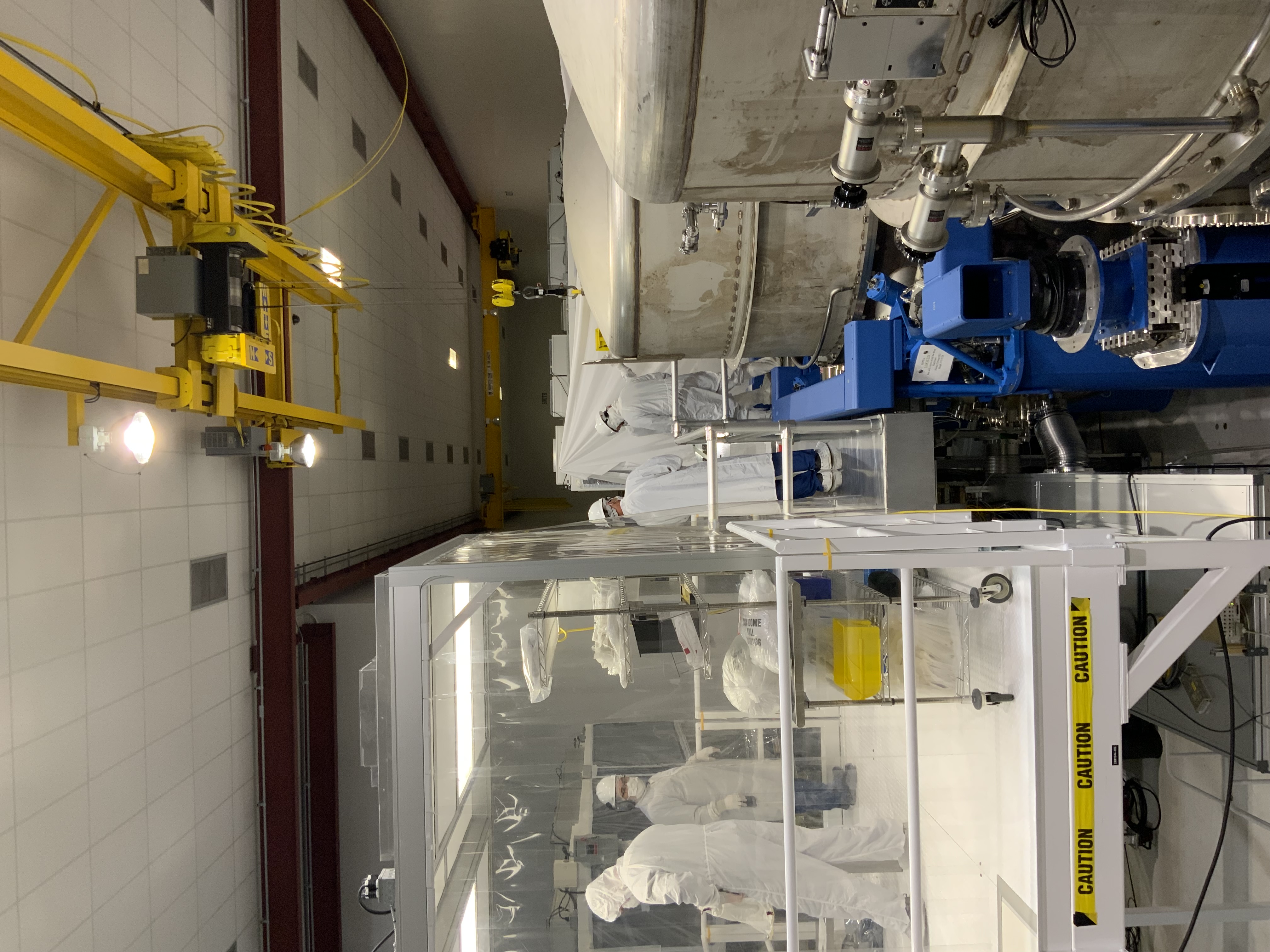


Adding some photos I took throughout the test stand measurements Tagging EPO.