Michael Antia, Paul Altin, Jess McIver
Summary: High winds are impacting ASC control loops, manifesting as an increase in noise for three distinct frequency bands and glitches at 5 Hz.
This is a follow up to a study initiated by Paul Altin, that confirms the increase of ASC loop noise during periods of high wind.
The lock stretches analyzed pertain to O1 and contain periods of both high and low wind.
The effect of high wind is evidenced by an increase in amplitude for the ASD (see GIFs by clicking the link at the end) at three distinct frequency bands which are:
· 0 – 1 Hz
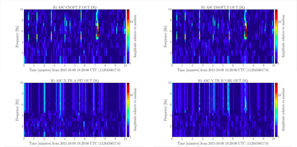
· 4 – 20 Hz * Glitches occur in this band (see attached spectrogram.png)
· 20 – 40 Hz
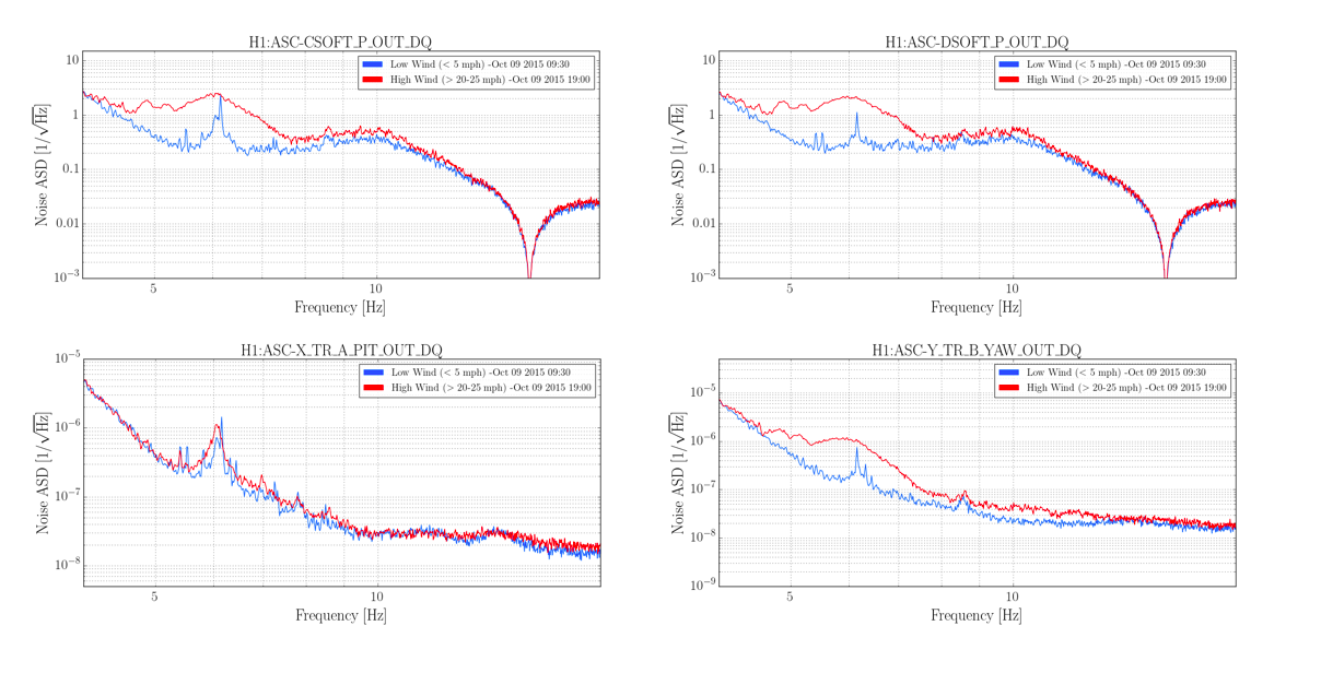
The ASD for Oct 9th 2015 shows an increase in noise in 4 – 20 Hz as can be seen in the four figures in the ASD.png attachment. The four channels chosen are representative of behavior seen for CARM control, DARM control and transmitted light at the end stations. The soft modes for CARM and DARM appear to be the most reactive.
The four figures in ASD.png each contain an ASD averaged over 30 minutes. Blue is the reference time during low wind. Red is related to the period of high wind.
For a more detailed visualization on the evolution of noise as wind speed increases, please see the link at the end.
Figures in the spectrogram.png attachment show recurring glitches during transition from low wind to high wind. This indicates that for the 4 – 20 Hz band, the increase in amplitude seen in the spectra GIFs is at least in part due to glitches.
Further study: The glitches will be further analyzed for the possibility of scattered light saturating the photo detector. In addition, we will investigate whether high wind causes lingering effects on ASC loop noise.
For more details, please see the study at the following link: https://wiki.ligo.org/DetChar/LHOWindASCStudies