patrick.thomas@LIGO.ORG - posted 17:35, Tuesday 28 June 2016 (28028)
Ops Day Summary
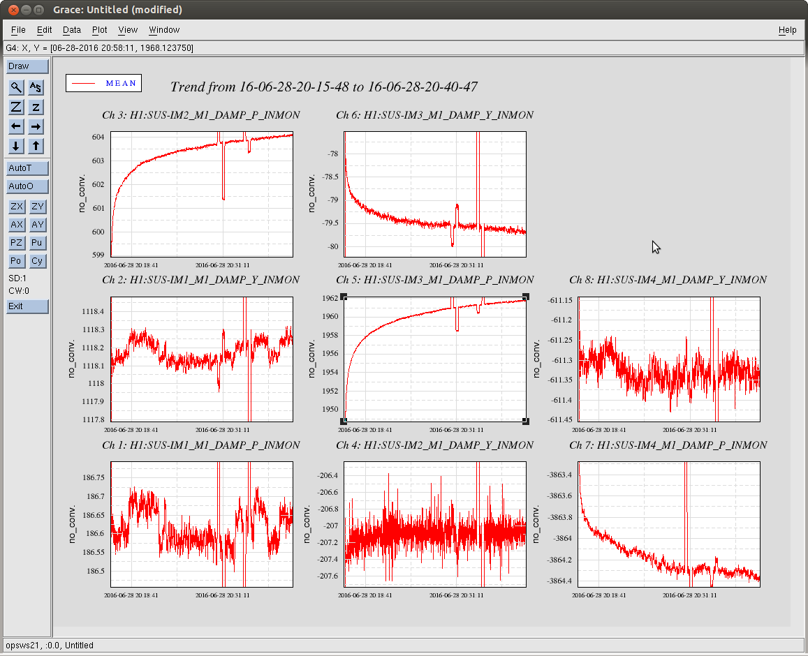
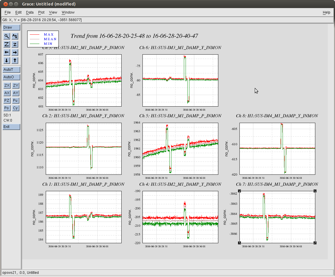
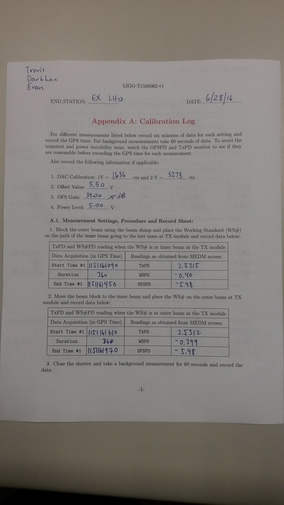
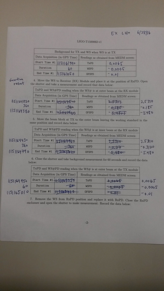
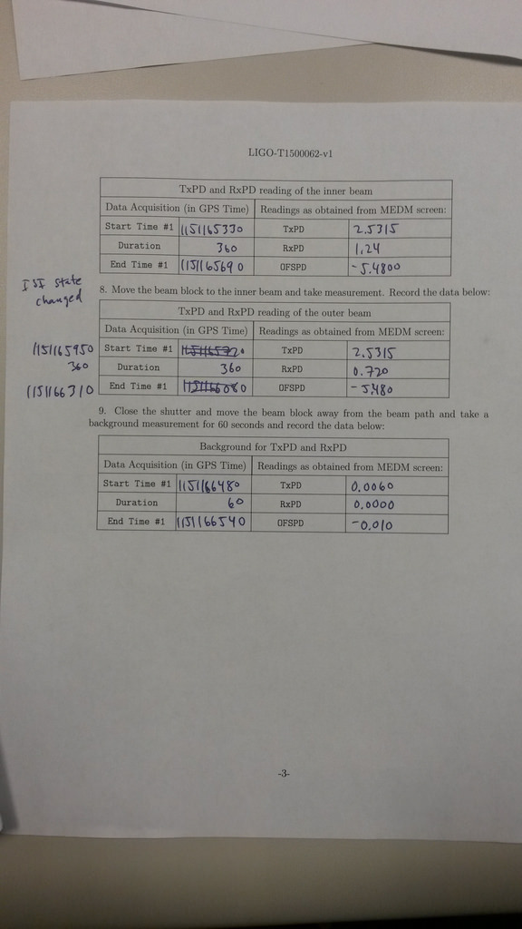
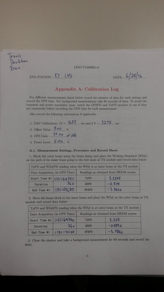
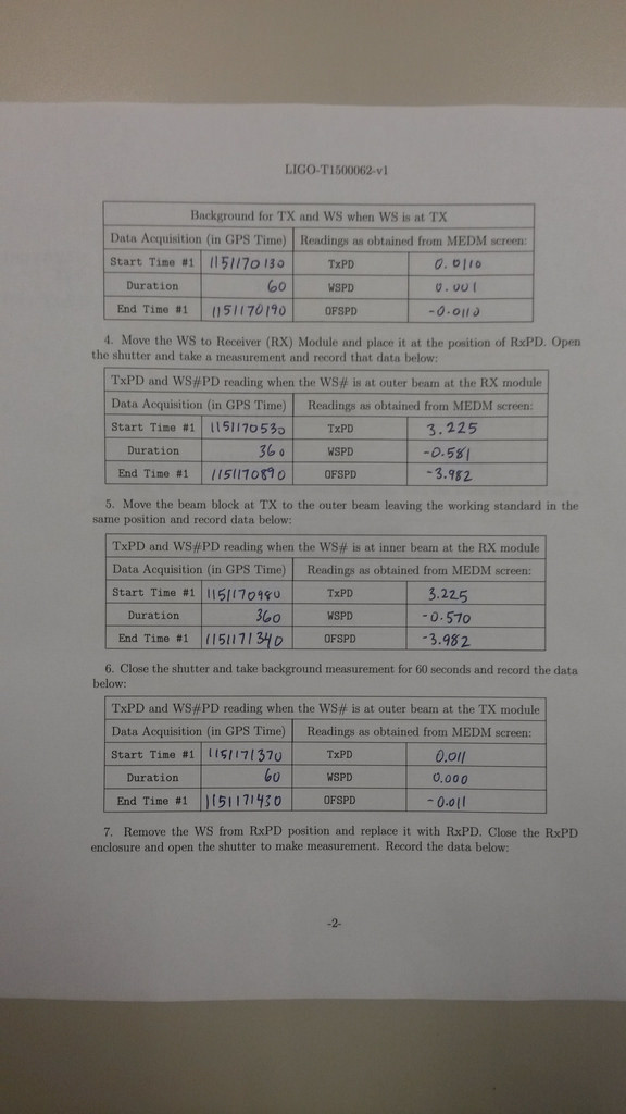
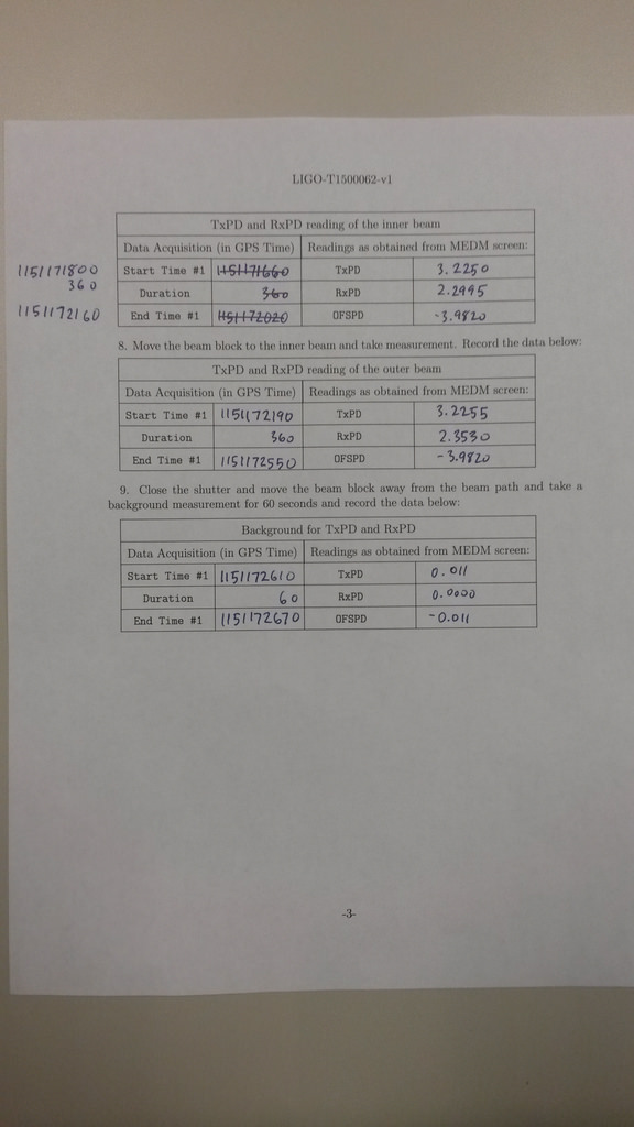
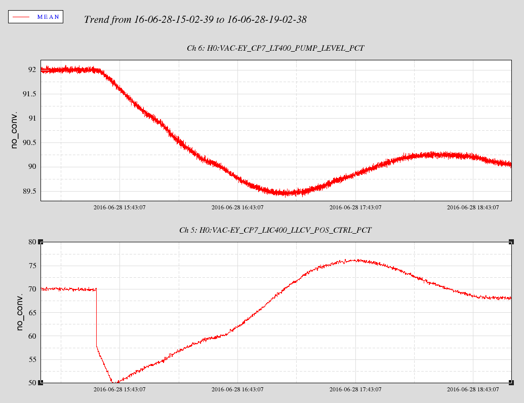
Cheryl recovered the optic positions and locked the arms on green. I completed an initial alignment and brought the IFO to DC_READOUT_TRANSITION.

Bubba, property inventory, LVEA
Travis, Darkhan and Evan to PCAL X

14:12 UTC Jeff B. and Peter in PSL
14:40 UTC Chis S. to end X to retrieve equipment from receiving area
15:08 UTC Coca Cola delivery truck through gate
15:23 UTC Gerardo to LVEA to retrieve wire
15:23 UTC Jim B. restarting guardian machine
15:23 UTC Karen and Christina to LVEA to clean
15:26 UTC Jeff B. and Peter out of PSL, Peter taking equipment back to anteroom
15:34 UTC John changed setpoint on CP7
Guardian reboot took everything to safe, interfered with PCAL work
15:40 UTC Jeff B. taking ETMX SUS back to aligned
15:48 UTC Bubba and Nicole to end Y and then end X for property management
15:52 UTC Peter done with chiller block investigation and DC blocker install
15:58 UTC Richard swapping IM2 satellite amp, power cycling IM3 and MC1 satellite amps
16:07 UTC Cheryl installing beam blocks on IOT2L
16:07 UTC Joe D. to LVEA to gather flex tubing
16:07 UTC Vinny to LVEA to work on infrasonic microphones
16:09 UTC LN2 delivery truck through gate
16:11 UTC mat delivery truck through gate
16:15 UTC Jeff B. to optics lab to store equipment
16:19 UTC Bubba lifting Styrofoam cooler off tilt meter at end Y to look at serial number
16:23 UTC Jeff B. done
16:27 UTC Cheryl done
16:40 UTC Vinny to EY VEA to work on infrasonic microphones
16:43 UTC Evan and crew done at end X
16:46 UTC Evan and crew to end Y
16:48 UTC retrieval of SR785 from beer garden
16:51 UTC Vern to SR2 by HAM4
16:58 UTC tractor trailer truck through gate to pickup forklifts
17:02 UTC Nutsinee to LVEA
17:05 UTC Richard to LVEA to replace DAC cards in SUSB123 and SUSH2A IO chassis
17:05 UTC Gerardo to LVEA to replace wire for HAM1 vacuum gauge
17:07 UTC Dave B. powering down SUSB123 and SUSH2A frontend computers so Richard can replace DAC cards
17:11 UTC SUSB123 and SUSH2A powered down
17:15 UTC Nutsinee done
17:19 UTC Vinny back from end Y, going to end X
17:22 UTC Dave M. swapping cables on Newtonian Noise seismometers in LVEA
17:26 UTC Richard done replacing DAC cards, Jim B. powering on SUSB123 and SUSH2A frontend computers
17:40 UTC Dave B. restarting ISI ITMY model
17:40 UTC Jim B. restarting models on SUSB123 and SUSH2A frontend computers
17:51 UTC Dave M. done
Satellite amp modifications are done
17:59 UTC Richard to LVEA to reinstall modified whitening chassis
18:00 UTC Vinny back from end X
18:11 UTC Dave M. to LVEA to make measurements of Newtonian Noise array
18:12 UTC Christina and Karen done cleaning at end X, coming back to OSB
18:12 UTC BSC HEPI and IOP models need restarting, not just ISI
18:16 UTC BS seismic HEPI and IOP model restart
18:19 UTC Vinny to LVEA to calibrate microphones
18:19 UTC Nutsinee removing TCSY AOM from water supply
18:25 UTC Kiwamu restarting OMC PI model
18:25 UTC Dale leading tour in CR
18:25 UTC LDAS work starting on nds0
18:28 UTC Travis done
18:28 UTC Richard reinstalling modified AA chassis
18:34 UTC Daniel done Beckhoff work
18:36 UTC Bubba to end X for property management
18:39 UTC Richard done installing modified AA chassis
18:39 UTC Dave restarting OMC PI model
18:42 UTC Vinny done calibrating microphones
18:46 UTC Gerardo done at HAM1
18:49 UTC Filiberto power cycling CPS fanout
18:51 UTC Dave B. restarting PI model
18:52 UTC SEI ITMx (HEPI & ISI) (Dave)
18:52 UTC Kyle to end X and end Y VEAs to take photographs and serial numbers of VAC equipment
18:57 UTC Volker to optics lab to retrieve optics posts
19:02 UTC Dave B. restarting end station HEPI and ISI models
19:27 UTC SUS ETMY PI model
19:31 UTC Jeff K. and Jim W. starting recovery of optics in HAM2
19:38 UTC DAQ restart
19:44 UTC Kyle back, reports end X is laser hazard and end Y is laser safe
19:55 UTC Christina opening OSB receiving door
20:09 UTC Bubba and Ernest to LVEA for property audit
20:15 UTC Filiberto to LVEA to reset cable on HAM4 SR2
20:39 UTC Kiwamu to LVEA to check with Nutsinee
20:57 UTC Nutsinee done, closed tables, reopened light pipe
20:57 UTC Dave B. taking nds1 down
21:01 UTC Starting IFO locking recovery
21:06 UTC Kiwamu to LVEA to realign REFL cam
21:09 UTC Bubba to end stations for property audit
21:15 UTC Nutsinee to TCS racks for CO2 X
21:16 UTC Starting initial alignment
21:19 UTC Carl to end Y to take PI measurements
21:19 UTC Nutsinee back
21:27 UTC Kiwamu done
21:28 UTC Kiwmu to HAM6 to measure DC QPD whitening
21:36 UTC DAQ work complete
21:49 UTC Bubba done property management in VEAs
22:08 UTC Travis to end Y to check illuminator
22:09 UTC Fred taking UW REU students into LVEA
22:55 UTC Initial alignment complete
22:57 UTC Carl done
23:04 UTC Fred and UW REU students out of LVEA