gabriele.vajente@LIGO.ORG - posted 11:42, Wednesday 29 June 2016 - last comment - 11:45, Wednesday 29 June 2016(28054)
Brute force coherence
Lisa asked me to run a BruCo scan on data from this elog entry: 27990 (June 28, 6:00 - 6:10 UTC)
The report is available at the following address:
https://ldas-jobs.ligo.caltech.edu/~gabriele.vajente/bruco_1151128817/
Instead of CAl_DELTAL I used directly the OMC_DCPD_SUM signal. The reason is that the usual calibration of CAL_DELTAL does not seem to be correct anymore.
In summary:
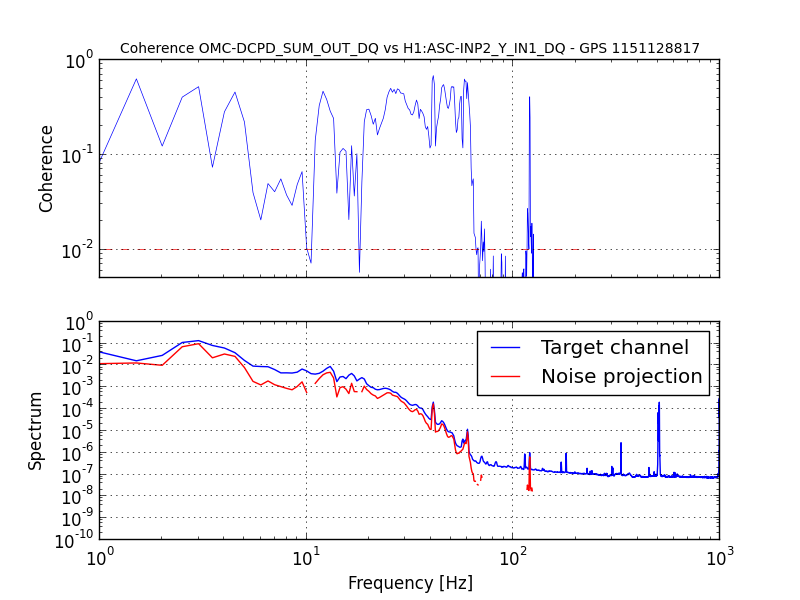
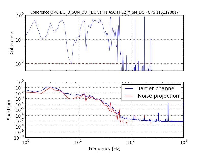
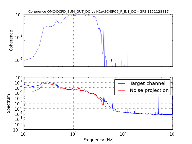
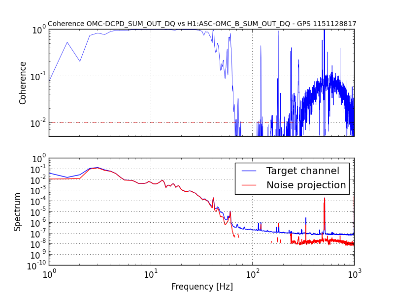
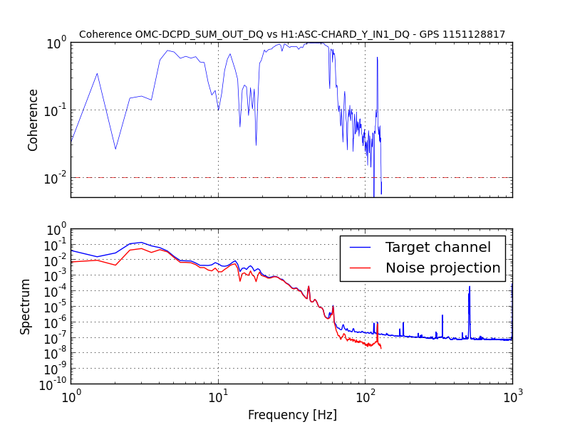
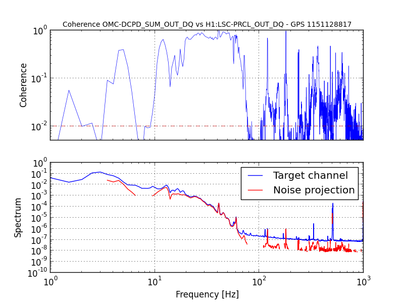
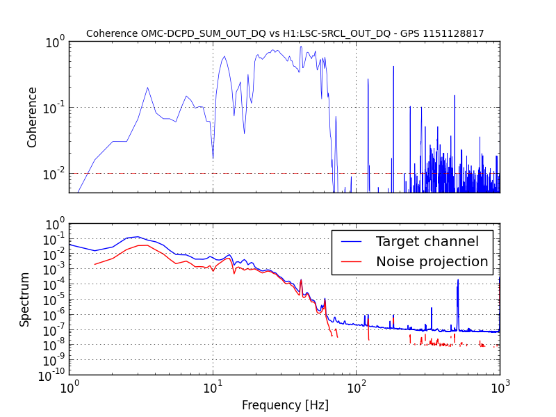
- All noise below ~70 Hz is dominated by alignment signals (CHARD, SRC, PRC2, PRC1, INP2). CHARD seems to be the one with largest coherence. There's also large coherence with ASC-OMC_A/B_SUM. I'm not sure if this is ok (they may be the same DCPD signals) or if those signals are sampling the beam before the OMC. In the latter case, it might indicate that the coupling of angular noise goes through some high order modes or clipping.
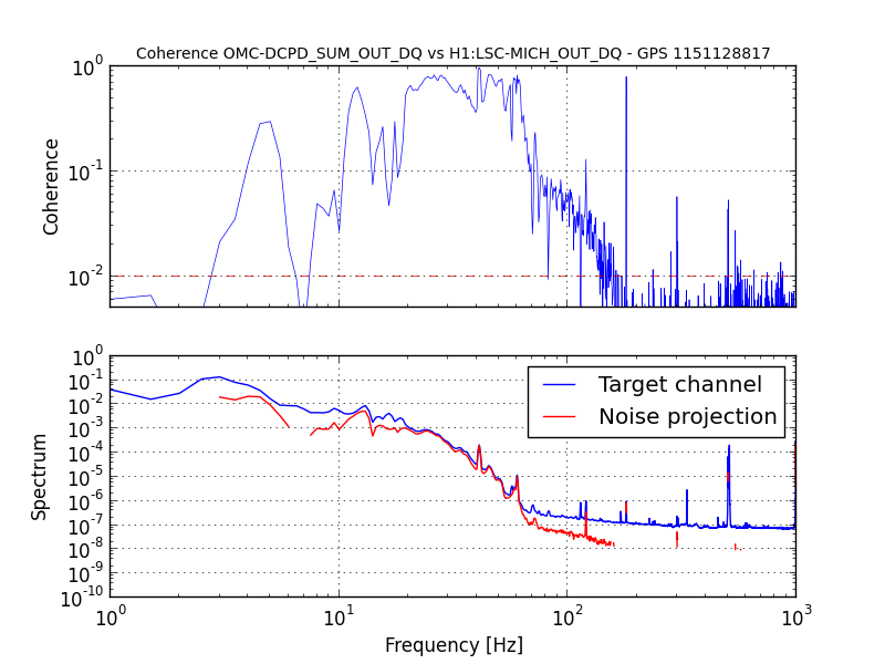
- However, coherence is also large with MICH / PRCL / SRCL, so it's hard to say what's going on. Are the auxiliary channels feedforward paths on?
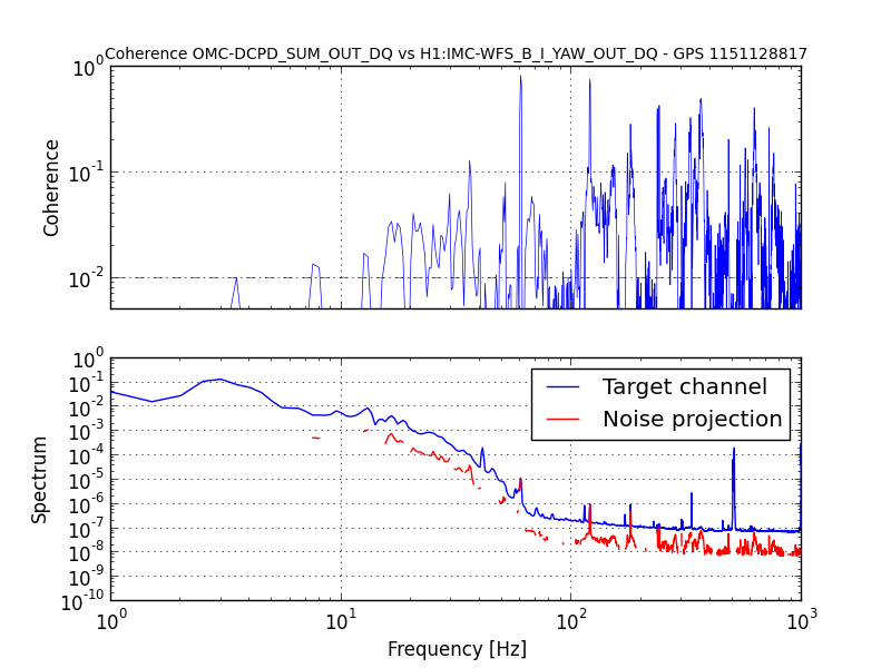
- At higher frequencies I couldn't find much going on, except maybe a larger than usual coupling with IMC jitter, see last plot.
For future reference, to run BruCo you can follow this procedure
- log in into one of LDAS machines, for example ldas-pcdev1.ligo-wa.caltech.edu
- download the bruco code from the git repository https://github.com/gabrielevajente/bruco
-
read the first lines of the bruco.py script for instructions. To produce the report above I used the following command:
./bruco.py --ifo=H1 --channel=OMC-DCPD_SUM_OUT_DQ --gpsb=1151128817 --length=600 --outfs=4096 --naver=300 --dir=~/bruco_1151128817 --top=100 --webtop=20 --xlim=1:1000 --ylim=1e-10:1
Images attached to this report
Comments related to this report
Thank you, Gabriele.