conor.mow-lowry@LIGO.ORG - posted 17:50, Thursday 23 June 2016 (27941)
New ETMY BRS sensor correction filters
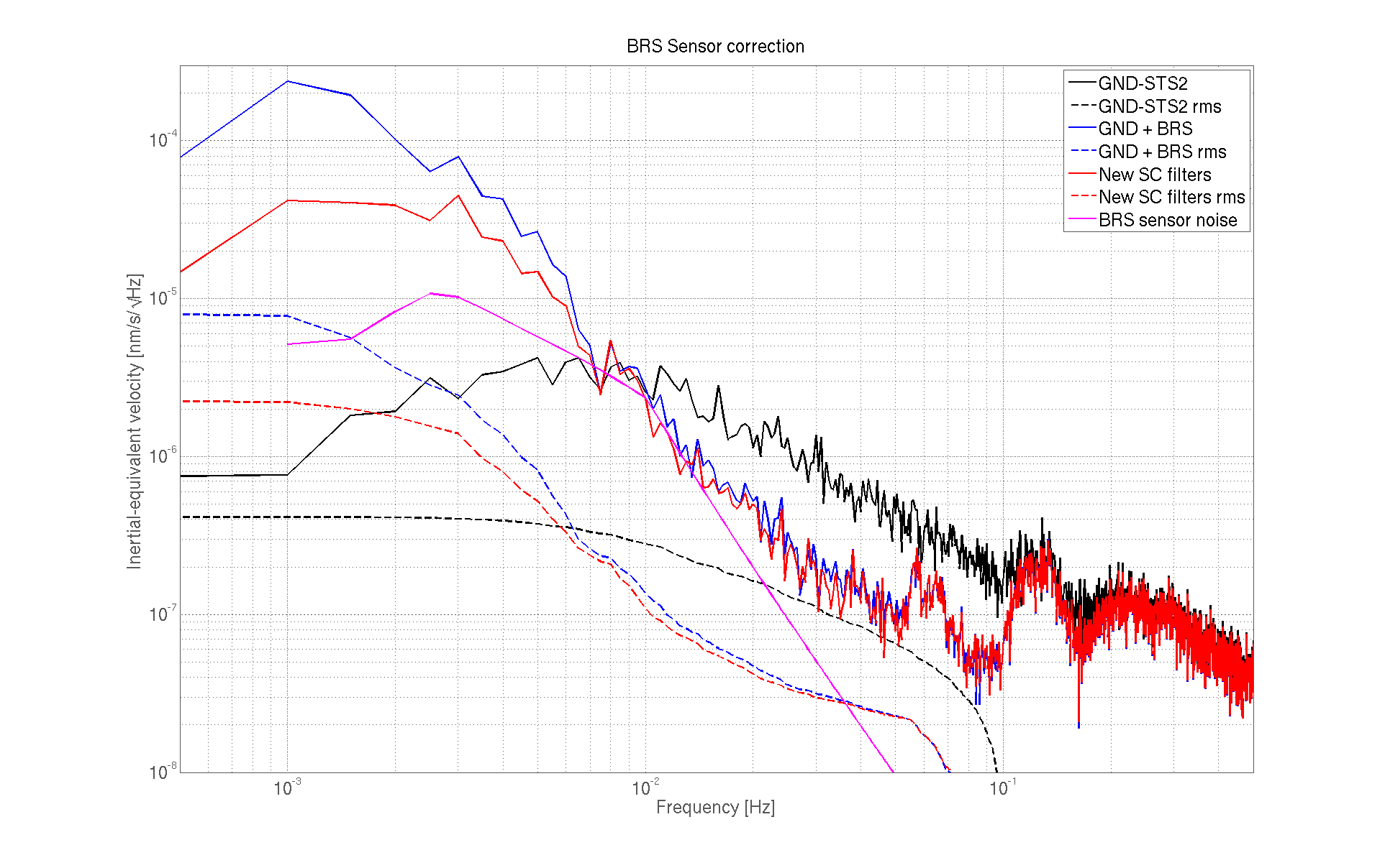
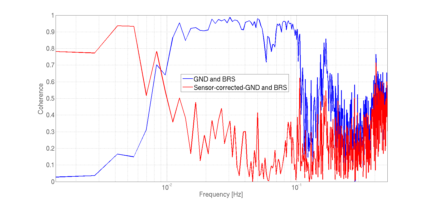
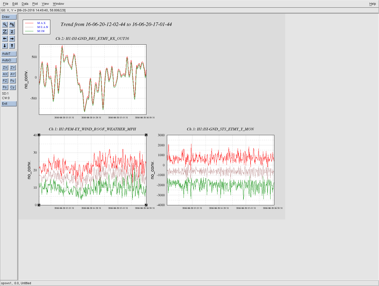
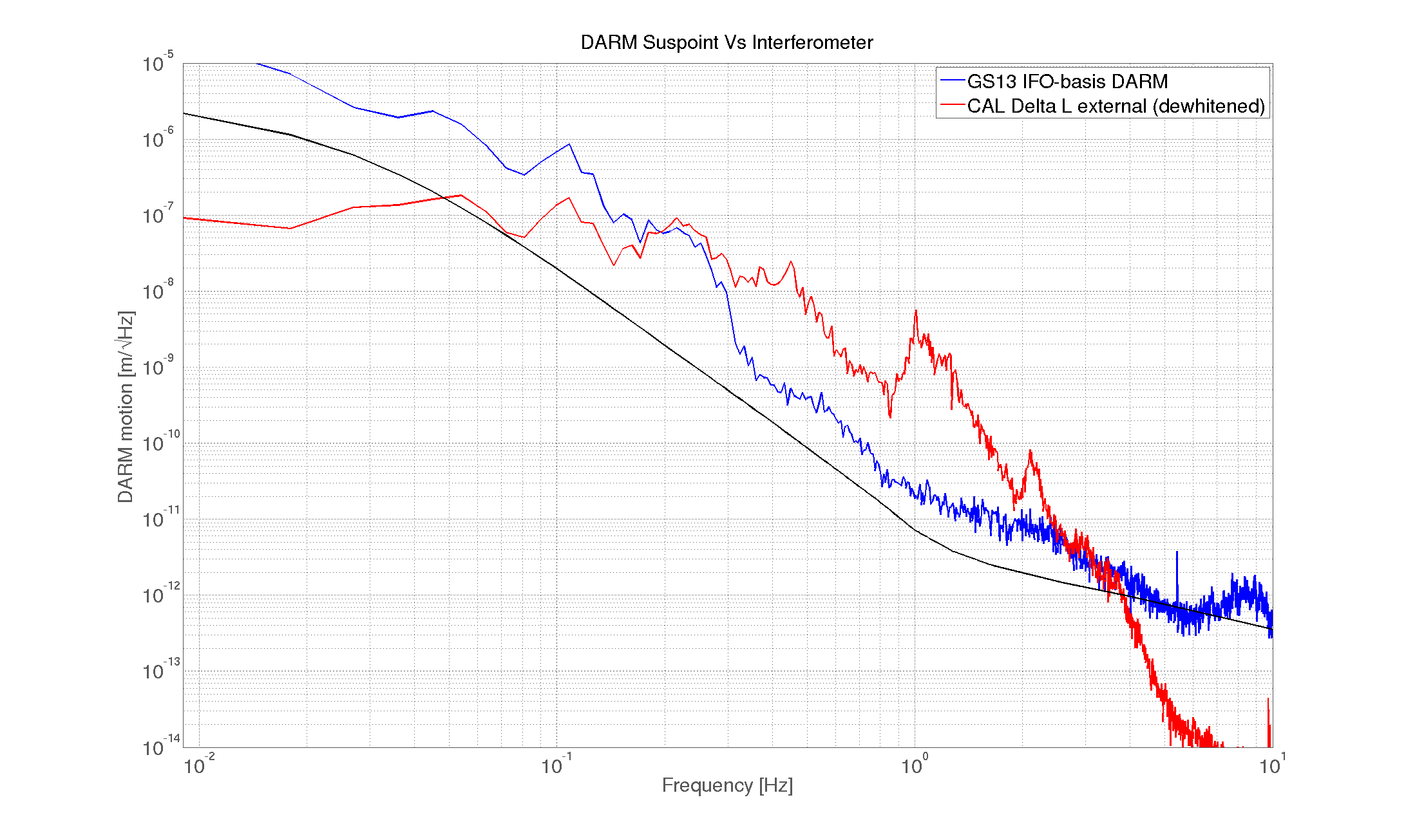
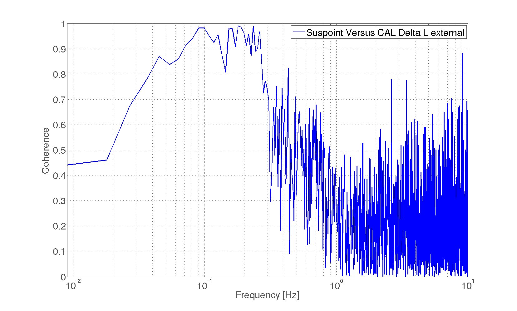
Conor, Jeff, Jim, Krishna

After generating a model that can do offline sensor correction, I played around with the plant inversion, unit conversion, and high-pass filtering in the BRS sensor correction path.

Two major points became apparent:
1) The BRS plan inversion is effectively providing some noise gain below 8mHz. By moving the poles in this filter close to the high-Q zero, a free 10dB can be won at low (f<5mHz) frequencies.

2) To improve correction at 10mHz, the STS2 needs some plant inversion. Instead, we can AC-couple the BRS at the same frequency and Q as the STS2. This means moving the poles
in the filter 'GND_SENSCOR_ETMY_STS_Y_ROTVEL' FM3 until they match the STS2. The manual says 8.33mHz, Q = 0.707, but I found better subtraction performance with 7mHz, Q = 0.7.
I had to push the pole in FM1 'acc_to_vel' from 2mHz to 1mHz to avoid phase loss. Additionally, FM2 'match', is now -0.774, about 15% lower than before.

These changes make some small gains at low frequencies, for a total of about 4x RMS improvement at 1mHz. The offline sensor correction goes from the Blue to the Red traces
in attachment 1 (BRS_sensor_correction.png).

The coherence tells a nice story: Nearly all coherence is subtracted from 0.1Hz down to ~30mHz (where BRS sensor noise becomes significant). At higher frequencies, they remain as
coherent as before since the wind drives translation as well as tilt, and we're only subtracting tilt. At low-f, the GND sensor is dominated by BRS noise and they become coherent again.

Sensor correction was trained using 5 hours of consistent wind (attachment 3) GPS time: 1150459291  -- 20 June 2016 ~17:01 UTC
Images attached to this report