[Jenne, Peter]
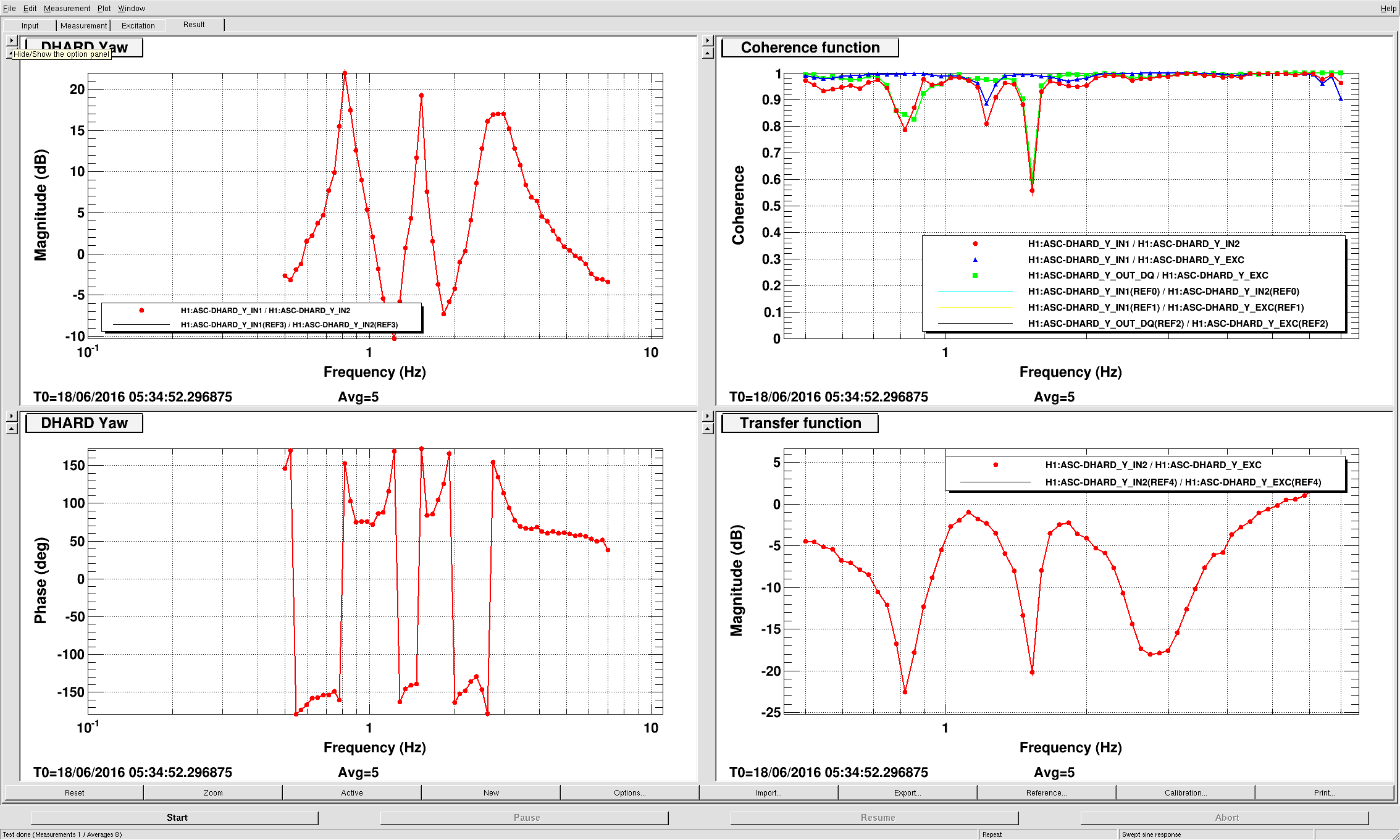
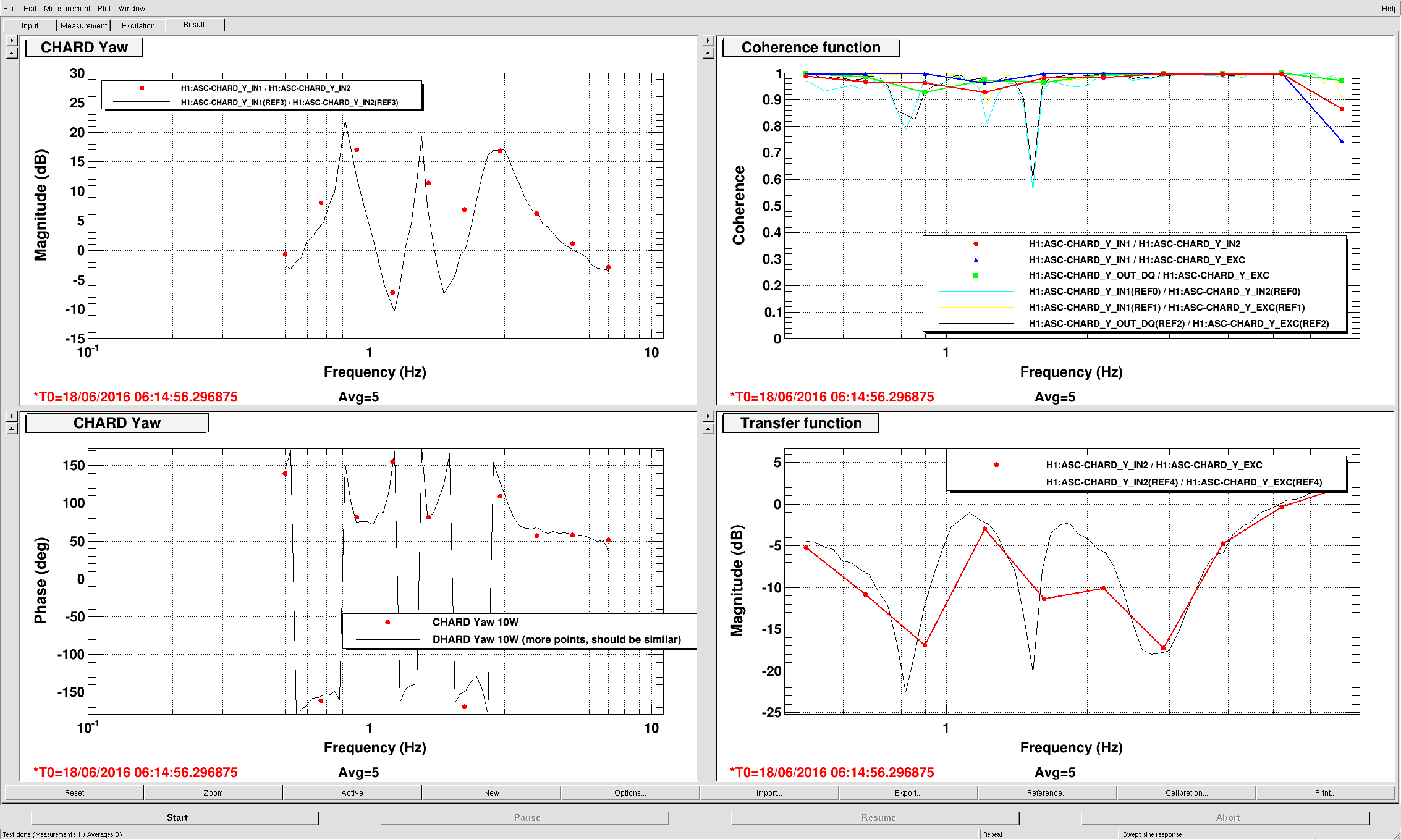
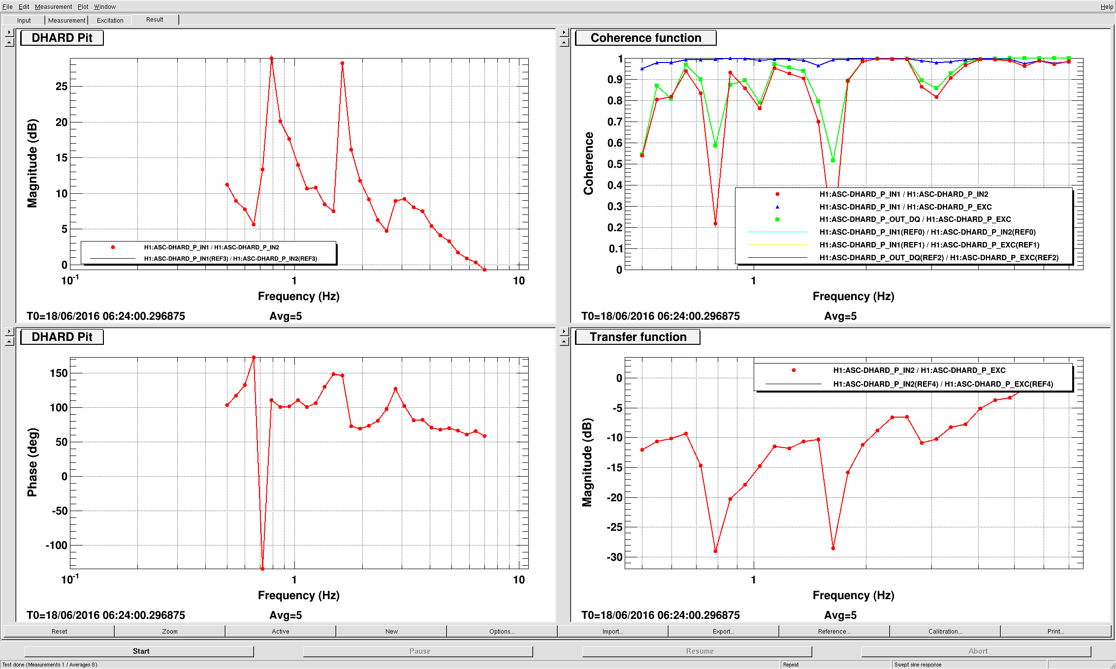
Tonight we were able to get to DC Readout, and increase the power to 10W. While there, we measured all of the ASC HARD loops. In order to get to 10W, we kept SRC1 open (already was written into the guardian), and had to move SRM to keep POP90 low (Evan said he didn't have to do that last time he was increasing the power).
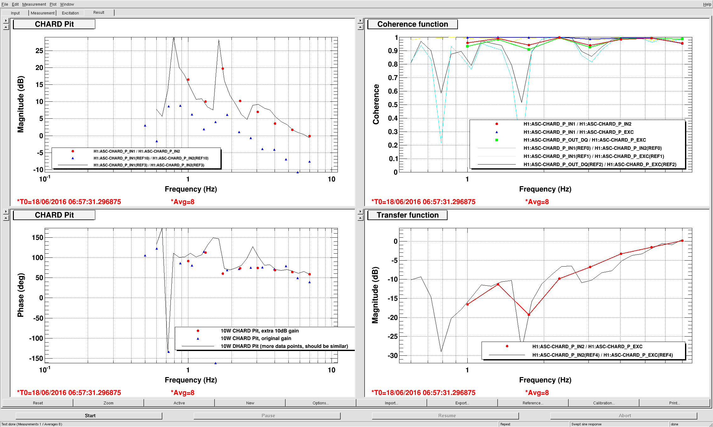
We determined that CHARD Pit really had too little gain (Sheila and Haocun saw this in alog 27617, but weren't sure if they belived the measurement). We increased the gain of CHARD Pit by 10dB, so now it goes to -60 rather than -21 in EngageReflPopWFS.
We found that the boosts were different for Pit versus Yaw, but the more aggressive one (can't remember which was which right now) was too aggressive, so we made all the boosts be gentle single pole, single zeros.
We tried the boosts, and they worked well at 10W (no OLG measurement taken though...). They are now in the IncreasePower state of the guardian, coming on after the laser power is above 10W.
We tried to increase the power further, but both times we lost lock fairly quickly (once at 20W, and the second time at 15W). It looks like the MICH ASC loop's error signal is no good at higher powers - it looks like the BS is being misaligned by the loop. For the 15W loop I opened the MICH ASC loop when it became clear that it wasn't going well, and that let us hold the lock for marginally longer, but not by much. "Not going well" means here that POP90 was increasing, but POP18 and AS90 were starting to decrease significantly.
As a side note, while at 10W I noted that the AS36I signals are still responsive to SRM, although the combination is definitely different from the 2W input matrix combo.
At this point, we need to get a better MICH error signal so that we can hold lock at higher powers. We should consider something like alog 20699, where we altered the SRC1 and MICH input matrix values to deal with this change as we increase the power. The old version of the guardian in the svn (ISC_LOCK rev 12339) has the values that we used to use. Daytime-us are going to look at this.


