Summary:
After the test on CW injections (LHO alog 27409), I decided to revisit the ETMX Pcal actuation function and inverse actuation filter because I have some concern that the new actuation function is not as accurate as I initially desired. Following a similar procedure as LHO alog 27176, I created new filters and obtain an inverse actuation function that is within 5% in magnitude and 5 degrees of phase up to 2 kHz, and within 5% and ~10 degrees of phase up to 3 kHz. The new inverse actuation filters are loaded into the PINJ_TRANSIENT bank. Waveforms using the inverse actuation filters should assume a time advance of 240 usec. Attached are the actuation function files, one without the 240 usec delay and one with the 240 usec delay.
Details:
In the same way as LHO alog 27176, I created new AI analog and AI digital approximations. The new approximations are actually not very good by themselves, but when used in conjunction with all of the filters in the PINJ_TRANSIENT bank, it accurately reproduces the true Pcal actuation function within 5% in magnitude and 5 degrees in phase up to 2 kHz.
Changes:
- Analog AI approximation was [8k,8k:7.15k,7.15k], and is now [7.9k,7.9k:3.5k,3.5k]
- Digital AI approximation was [7k,7k,7k,7k:pair(4300,30),pair(7000,50)], and is now [7.5k,7.5k,7.5k,7.5k:pair(4500,40),pair(6500,60)]
- The three 7k poles were moved to 7.5k
In addition, I used the Matlab quack3 function to produce SOS filters to be copied into Foton. I found that entering the values as zpk in Foton did not reproduce the Matlab results. A transfer function was exported from Foton and loaded into Matlab for detailed comparison. No significant differences were found
Attached are figure files showing the comparison of the AI analog/digital approximations, comparison of the approximate Pcal actuation function to the real actuation function, comparison of approximate inverse actuation function to real inverse actuation function, and the impulse response of the inverse actuation filters. Also attached is the actuation function with and without a 240 usec delay for use with the CW hardware injections.


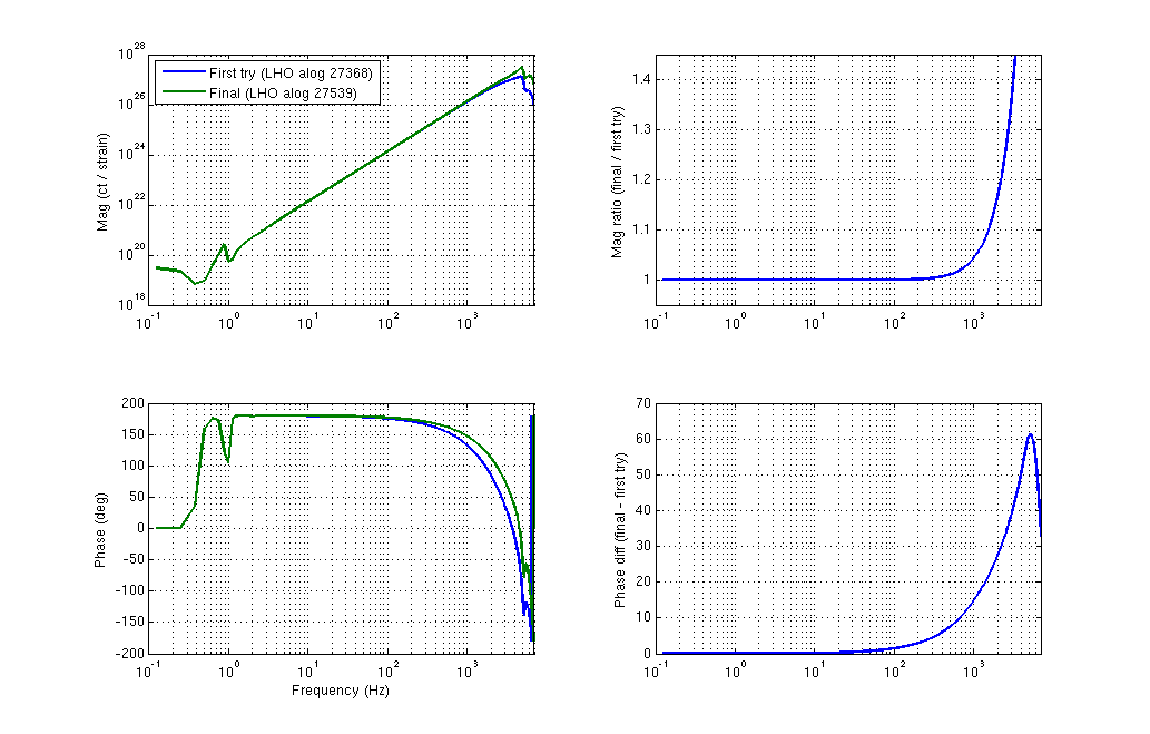
Attached is a comparison of the first try inverse actuation function (LHO alog 27368) and this version that fixes some of the issues described above.