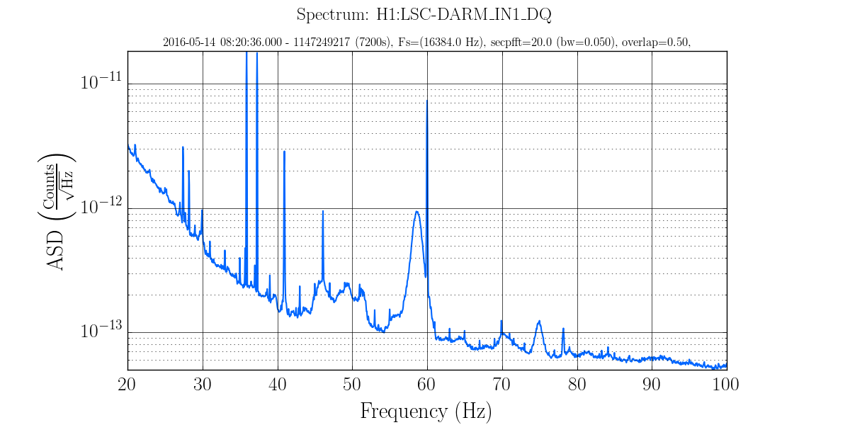
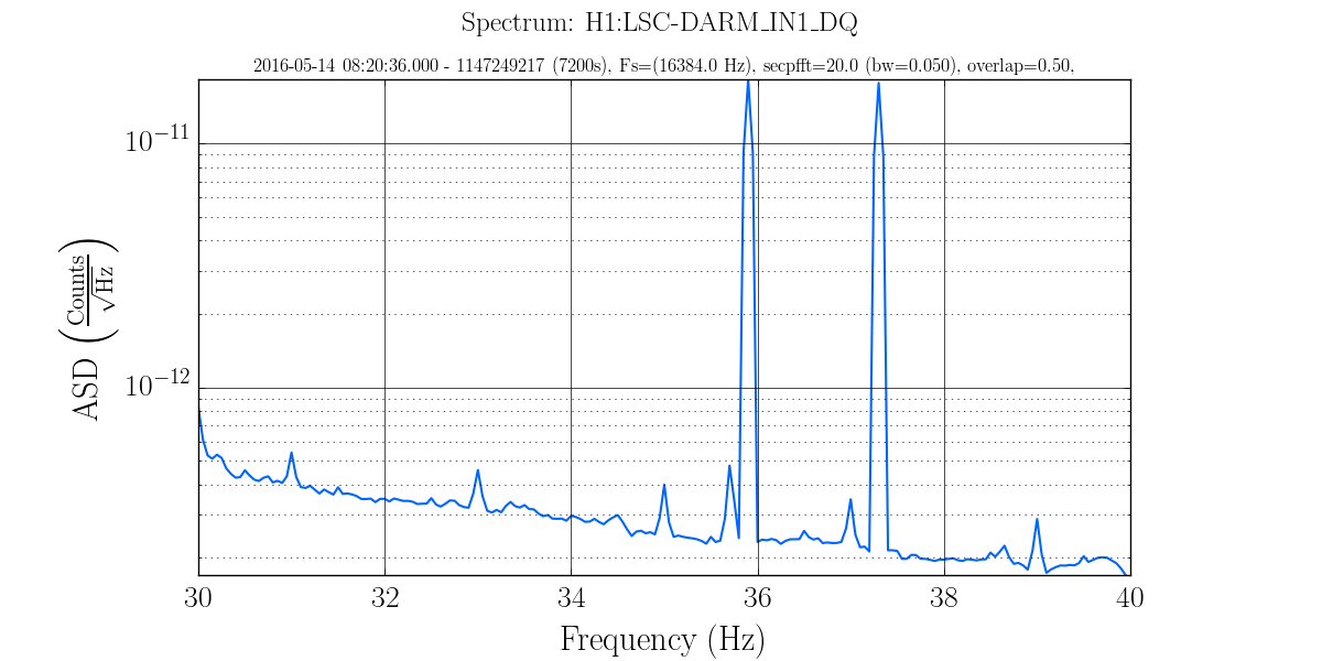
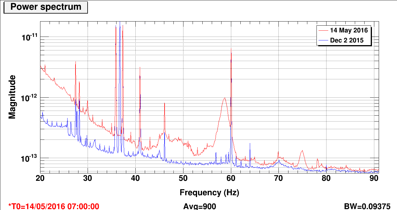
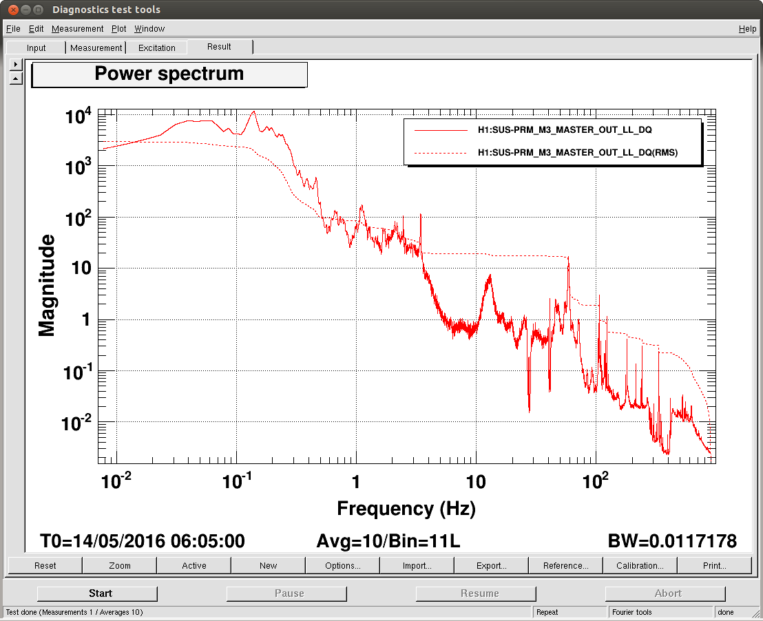
OMC WD would not UNtrip, Dave had to restart IOPSUSH56 to clear this. By restarting these, HAM5,6 also tripped.
We are currently untripping everything.
The SSD RAID for h1tw0 has failed, so h1tw0 is down until we can get it fixed. FRS 4228
I reduced one heater, HC1B, from 10ma to 9ma control current at 1:47 local time.
I have revamped my initial alignment lazy script and made a new medm to help operators and commissioners bring up what they need a bit faster.
The Script:
Location: /userapps/.../isc/h1/scripts/Init_align_lazy.py
Action: This will bring up 5 StripTools(XARM_GREEN_WFS.stp, YARM_GREEN_WFS.stp, PITCH_ASC_INITIAL_ALIGNMENT.stp, YAW_ASC_INITIAL_ALIGNMENT.stp, initall_alignment.stp) as well as the new medm I made (INIT_ALIGN.adl). The script will arrange them on the left monitor in a 3x2 grid. They can then be moved if so desired. If any of these windows are open in another workspace, the window manager will get confused and move the other one, so keep that in mind of they aren't in their proper positions.
I have aliased this in for "ops" as 'initial_alignment'
The medm:
Location: /userapps/.../isc/h1/medm/INIT_ALIGN.adl
Combines the ALIGN_IFO, X and Y ALS Guardians with the alignment sliders for ETMX, ETMY, ITMX, ITMY, BS, and PR3. These are the most commonly adjusted optics for IA.
I have not linked this medm off of the sitemap yet, but if/when I do it will most likely be under OPS.
Comments adn questions are always welcome.
Jenne noticed the control room symptoms of the ETMX ISI starting to ring up (H1:IMC-F_OUT16 on our Tidal.stp will be gin to oscillate [shot attached] along with the ASC control signals). I brought up the template to watch it and sure enough, ISI ETMX X was ringing up. I switched the X direction blend to the 90mHz and it imediately settled down.
I'm attaching screen shots of the environment control room tools to hopefully help.
TITLE: 1/14 Day Shift 16:00-00:00UTC (08:00-16:00 PDT), all times posted in UTC"
STATE Of H1: Observing at 78Mpc for 2hrs
OUTGOING OPERATOR: Travis
QUICK SUMMARY: wind <10mph, useism 0.4um/s, CWinj running, More calibration measurements today to come.
Title: 1/14 Owl Shift 8:00-16:00 UTC (0:00-8:00 PST). All times in UTC.
State of H1: Observing
Shift Summary: Unlocked at the beginning of my shift. After an IA, it locked up pretty quickly. Then there was an lockloss due to EQ. After EQ ringdown, we stumbled through the CARM section a few times before getting back to NLN.
Incoming operator: TJ
Activity log:
9:27 Locked at NLN
9:30 cleared ETMx TIM error
9:32 Observing
10:06 Set to Commissioning to tweak TMS in an attempt to get POP power higher (it wasn't drifting down, just not as high as usual,15800). Unsuccessful.
10:13 Observing
11:42 Lockloss. EQ?
13:50 Locked NLN, attempting to tweak POP power again
14:08 Another unsuccessful POP attempt. I did however manage to ring up the ASC loops like crazy! Waiting for them to ring down.
14:21 Observing
Finally back to Observing after a few failed attempts.
According to our seismometers, it appears to be an EQ. The only thing showing on Terramon or USGS at the moment is a 5.1 near Wallis and Futuna with Terramon prediciting 0.17 um/s R-Wave. However, our seismos are already at ~1 um/s a few minutes before the predicted arrival time for this EQ.
After running through an initial alignment, we are back to Observing. The issue with PRM align mentioned in Jeff's summary seems to have been due to PRM alignment being far off (hundreds of urads). I restored them to earlier values and it locked without issue.
Activity Log: All Times in UTC (PT) 00:00 (16:00) Take over from TJ 00:19 (16:19) Kyle – Going to Mid-Y to overfill CP3 00:22 (16:22) Robert & Vinny – Going to End-X 00:54 (16:54) Kyle – Back from Mid-Y 01:50 (17:50) Robert & Vinny – Back from End-X 02:39 (18:39) Robert – Swept LVEA 03:11 (19:11) Lockloss – Commissioning activities 03:25 (19:25) Mag 6.7 EQ near Japan – R-Wave 12.9um/s estimated arrival at 04:00 (20:00) 03:25 (19:25) Mag 6.0 EQ near Bolivia 03:57 (19:57) Reset WD trips on BS ST1, ST2, and SUS 04:00 (20:00) Put IFO into DOWN until the ground settles down 08:00 (00:00) Turn over to Travis End of Shift Summary: Title: 01/13/2015, Evening Shift 00:00 – 08:00 (16:00 – 00:00) All times in UTC (PT) Support: Jenne, Evan H., Incoming Operator: Travis Shift Detail Summary: Hardware injections scheduled to start at 08:10 (00:10). While doing an initial alignment after a commissioning lock, were hit with two earthquakes at same time (6.7 near Japan, 6.0 near Bolivia). Seismic has rung up to 5um/s. Reset WD trips on BS. Put the IFO in DOWN until the earth calms a bit. Seismic calmed down enough to try initial alignment and locking. The initial alignment took longer than normal, but was mostly OK. Tried a couple of times but could not get PRM_ALIGN to move past REFL_WFS_CENTERING_PRX. I skipped this step. Trying to relock.
Evening Mid-Shift Summary
While doing an initial alignment after a commissioning lock; hit with two earthquakes at same time (6.7 near Japan, 6.0 near Bolivia). Seismic has rung up to 5um/s. Reset WD trips on BS. Put the IFO in DOWN until the earth calms a bit.
Robert did a sweep of the LVEA.
1615 - 1650 hrs. local -> To and from Y-mid Next CP3 manual over fill scheduled for Friday, Jan. 15th before 4:00 pm
Transition Summary:
Title: 01/13/2016, Evening Shift 00:00 – 08:00 (16:00 – 00:00) All times in UTC (PT)
State of H1: IFO locked in Commissioning mode for calibration work.
Outgoing Operator: TJ
TITLE: "1/13 Day shift: 16:00-00:00UTC (08:00-16:00 PDT), all times posted in UTC"
STATE Of H1: Nominal Lo Noise, Calibration ongoing
SHIFT SUMMARY: Locked for entire shift while Robert and commissioners did their calibration measurements.
INCOMING OPERATOR: Jeff B
ACTIVITY LOG:
I have scheduled 2 runs of 5 burst injections. The first run will begin at 12:10am PT (8:10 UTC), and end at 1:30am PT (9:30 UTC), the 5 injections are spaced 20m apart. The second run will begin at 4:30am CT (12:30 UTC), and end at 5:50am CT (13:50 UTC). Here is the updated schedule: 1136794217 2 1.0 burst_GPS_76.259_ 1136795417 2 1.0 burst_GPS_76.262_ 1136796617 2 1.0 burst_GPS_76.263_ 1136797817 2 1.0 burst_GPS_76.264_ 1136799017 2 1.0 burst_GPS_76.266_ 1136809817 2 1.0 burst_GPS_76.259_ 1136811017 2 1.0 burst_GPS_76.262_ 1136812217 2 1.0 burst_GPS_76.263_ 1136813417 2 1.0 burst_GPS_76.264_ 1136814617 2 1.0 burst_GPS_76.266_
O1 days 115-117. End of O1.
No restarts reported on all 3 days. No maintenance on Tue 12th.
Evan G., Jeff K.
Revisiting measurements Jeff made in the field [1],[2],[3] and new measurements with those I took in the EE lab, we compared with the UIM residuals measurements obtained using the Pcal and ALS DIFF measurements. Attached is a figure showing the electronics chain and comparing with the residuals obain. We find that the BOSEM electronics account for some of the residuals found in the UIM measurements, but not all. At this point, we have only clues, but no solid evidence for what remains of the residuals. We have three theories:
I set up in the EE shop a UIM driver, satellite box, and BOSEM to repeat Jeff's measurements and verify we observe the same effects. Indeed, I observed similar issues that Jeff had observed in his measurements from the floor. We put these measurements on top of the UIM actuation residuals measurement/model but, unfortunately, find that they are not completely accounted for by the electronics chain.
We started to think about what else could be going wrong with the residuals, but so far have come up with the only three theories above. To undertand this effect in more detail, Jeff is currently undertaking exploratory measurements of the UIM-->DARM and Pcal-->DARM to frequencies higher than 100 Hz. Hopefully these measurements will shine some light on this effect.
The quad model on the svn does not have UIM-PUM wire violin modes. I just drafted an update that does include these, which I used to generate the attached figures. I'll commit this update if it appears consistent with measurements.
The plot ViolinModes_12Jan2016.jpg compares the model UIM L to Test L transfer function with and without the UIM-PUM modes, but with the fiber modes in both cases. I guessed the UIM-PUM violin modes to be a Q of 100,000, but that could be off an oder of magnitude or two. The second figure plots the ratio of these 2 transfer functions.
According to this second figure, the UIM-PUM violin modes explain some, but not all of the discrepancy seen between the measurements and the model in the log above. So either the model is not correct, or there is still something in the feedback loops we are missing.
For the Bench measurements, the data is stored at:
/ligo/svncommon/CalSVN/aligocalibration/trunk/Runs/PostO1/H1/Measurements/Electronics/BenchUIMDriver/2016-01-12
Attached are plots showing the individual components of the coil driver electronics fitted with the vectfit program in Matlab and using LISO. I report the fitted LISO values below with respective uncertainties.
Dummy BOSEM connected, with output impedance network (see figure UIM_out_impedance.pdf):
Best parameter estimates: zero0:f = 84.1507169277 +- 1.627 (1.93%) pole0:f = 303.5726548020 +- 5.431 (1.79%) pole1:f = 127.6915337428k +- 3.535k (2.77%) factor = 2.2065872530m +- 17.45u (0.791%)
This fit shows the calibration of 2.2 mA/V, one zero at 84.15 Hz, and two poles at 303.57 Hz and 127.7 kHz.
BOSEM only (output impedance network divided out so only BOSEM transfer function remains, see figure UIM_bosem.pdf):
Best parameter estimates: zero0:f = 334.8526120460 +- 3.892 (1.16%) zero1:f = 1.2383234778k +- 43.39 (3.5%) zero2:f = 8.2602408615k +- 320.8 (3.88%) pole0:f = 747.0160319882 +- 27.6 (3.69%) pole1:f = 5.3613221192k +- 210.2 (3.92%) pole2:f = 25.8483289876k +- 310.1 (1.2%) pole3:f = 232.8627791989k +- 3.041k (1.31%) factor = 11.6075630096m +- 14.92u (0.129%)
For some reason, this transfer function is tricky to fit. These are the fewest number of zeros and poles I could put in LISO and still provide a good fit to the data. LISO does complain that strong correlation exists between pole1<-->zero2 and pole0<-->zero1. When I removed these pairs, the fit became much worse, so I left them in.
As a comparison with the full chain: digital AntiAcq x analog Acq (output impedance network) x BOSEM (see figure UIM_full.pdf). The model fits the measurement with 2% up in magnitude to 40 kHz, and within 1 degree in phase up to 50 kHz.
Finally, the previously shown plot in the original post divides out the full BOSEM measurement in the field ('field BOSEM'), but the model already takes care of the analog output impedance network, so this original plot was double-counting. I attach here a corrected version of the plot (see UIM_res_with_elec.pdf). This shows that the BOSEM does indeed correct for some of the excess residual, it is not the dominant contributor to the behaviour above ~60 Hz.
While investigating an issue with x1seibsctim04 Jim Batch and I noticed that the power supply on the x1seiex IO chassis was dead. We replaced the power supply with a spare unit from the self. The new power supply appears to be getting 5v (some leds where lit), but it would not turn on (the fans would start to spin up and then stop).
Further investigation is needed. For now x1seiex has been disconnected from the dolphin network and turned off.
FRS 4218
https://services.ligo-la.caltech.edu/FRS/show_bug.cgi?id=4218
From the FRS: --- Comment #1 from richard.mccarthy@LIGO.ORG --- Turns out the an ADC interface board had a short dragging the power supply down. Replaced the board and returned the unit to service.
For operators, you will notice that h1tw0 will be WHITE-boxed on the DAQ Detail medm (which you should be checking every shift in the Ops Checksheet).