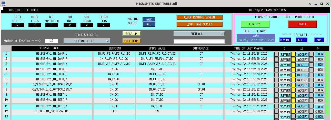
J. Kissel, T. Shaffer In the current O4 paradigm of SDF practice, we've minimized the number of .snap files to track by accepting the settings of some suspension whose setting don't change between "IFO down" and "Observing." That includes SUS RM1 and RM2, which live on the sushtts model -- that also now is home to PM1. RM1 and RM2 are ALIGNED at the moment, with damping loops and alignment offsets ON, and yet their settings do not show up as "different" from the safe.snap. This disagrees with the principle of "safe" but it's how we're doin it. As such, I've accepted PM1's settings in the ALIGNED state into the sushtts safe.snap.
TJ, Ryan C, Oli, Camilla. WP#12561
Randy had forklifted ISCT1 just outside of the cleanroom. We pushed ISCT1 back into place and checked it's location and height. Removed yellow VP covers and replaced bellows, then removed guillotines.
Oli, Edgard, Jeff, Brian
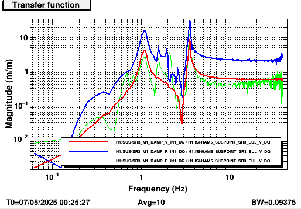
This post is meant to give a clearer explanation of the work in [LHO:84296] and its many comments. We are trying to find a new set of gains for the M1_OSEMINF filter banks for SR3 to calibrate the OSEMs to be in agreement with the HAM5 GS13s.
To do so, we drive the HAM5 ISI in { X , Y , Z } and record the response of the relevant OSEMs between 5 to 15 Hz. At these frequencies, the M1 stage of the suspension should start to become inertial, and the M1_DAMP / SUSPOINT response of each individual OSEM should asymptote to -1, because the OSEMs would be measuring their support point on the cage [barring internal dynamics of the cage itself].
To increase the accuracy of the calibration, we use the MATLAB model of the HLTS and use the full extent of the 5-15 Hz data instead of only the asymptotic behavior.
I post here the code used to generate these results. The code requires the new Common/MatlabTools/ExportedModels folder from the SusSVN [LHO:84458]. The detailed results of the calibrations mentioned is shown below.
_____
Adding hera a few bits of information that were missing from the original post, together with an updated version of the script.
_______________________________________________________________________
To compensate for the OSEM gain changes, we estimate that the H1:SUS-SR3_M1_DAMP loops must be changed by a factors of:
L gain = 0.743 * (old L gain)
T gain = 0.724 * (old T gain)
V gain = 0.549 * (old V gain)
R gain = 0.549 * (old R gain)
P gain = 0.691 * (old P gain)
Y gain = 0.743 * (old Y gain)
The calibration will change the apparent alignment of the suspension as seen by the at the M1 OSEMs
NOTE: The actual alignment of the suspension will NOT change as a result of the calibration process
The changes are computed as (osem2eul) * gain * inv(osem2eul).
Using the alignments from 2025-05-07_0000 (UTC) as a reference, the new apparent alingments are:
DOF Previous value New value Apparent change
---------------------------------------------------------------------------------
L -4.3 um -2.6 um +1.7 um
T -19.7 um -14.2 um +5.4 um
V -24.0 um -8.4 um +15.6 um
R -490.6 urad -219.3 urad +271.4 urad
P -300.2 urad -203.8 urad +96.5 urad
Y -569.3 urad -422.5 urad +146.8 urad
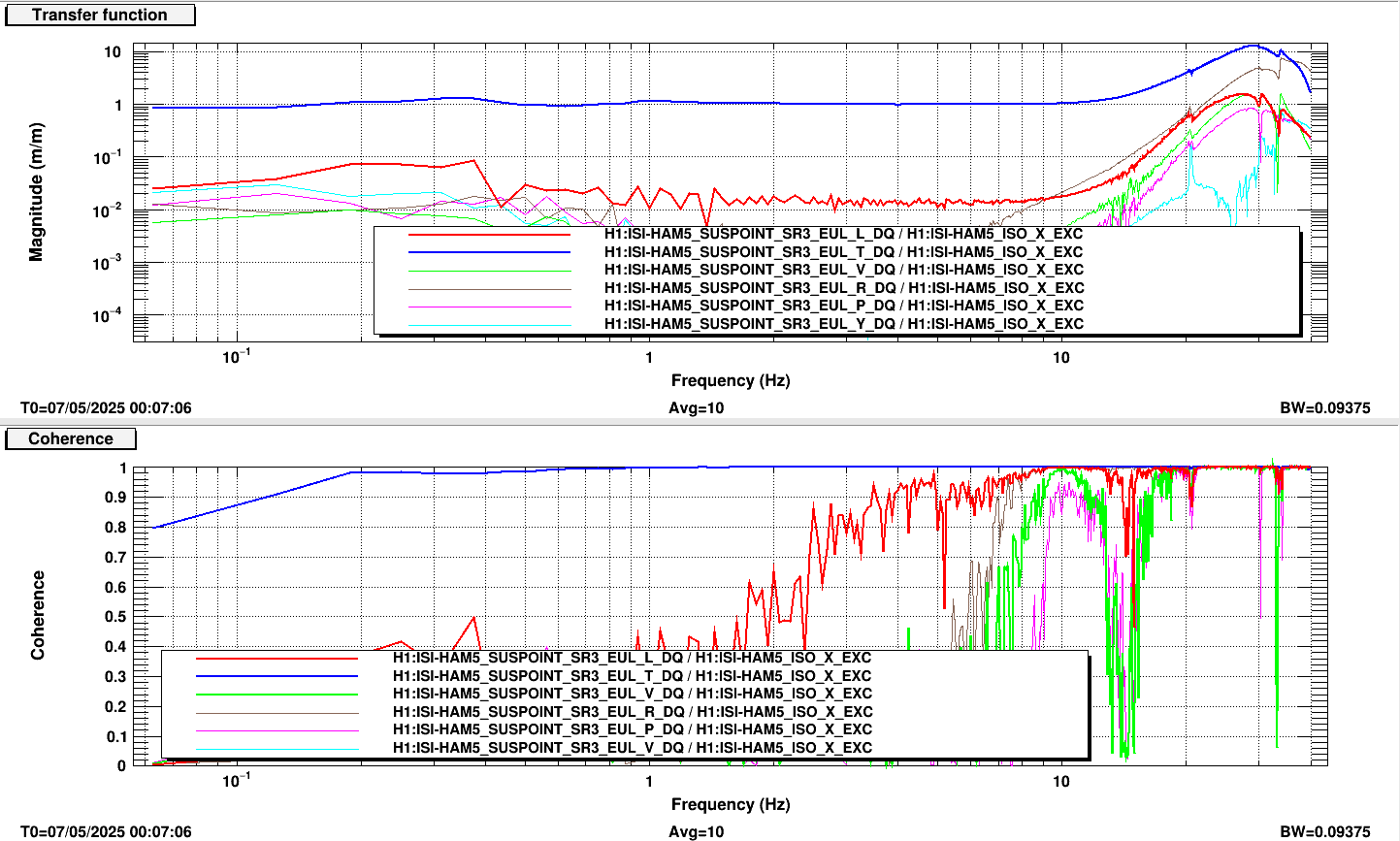
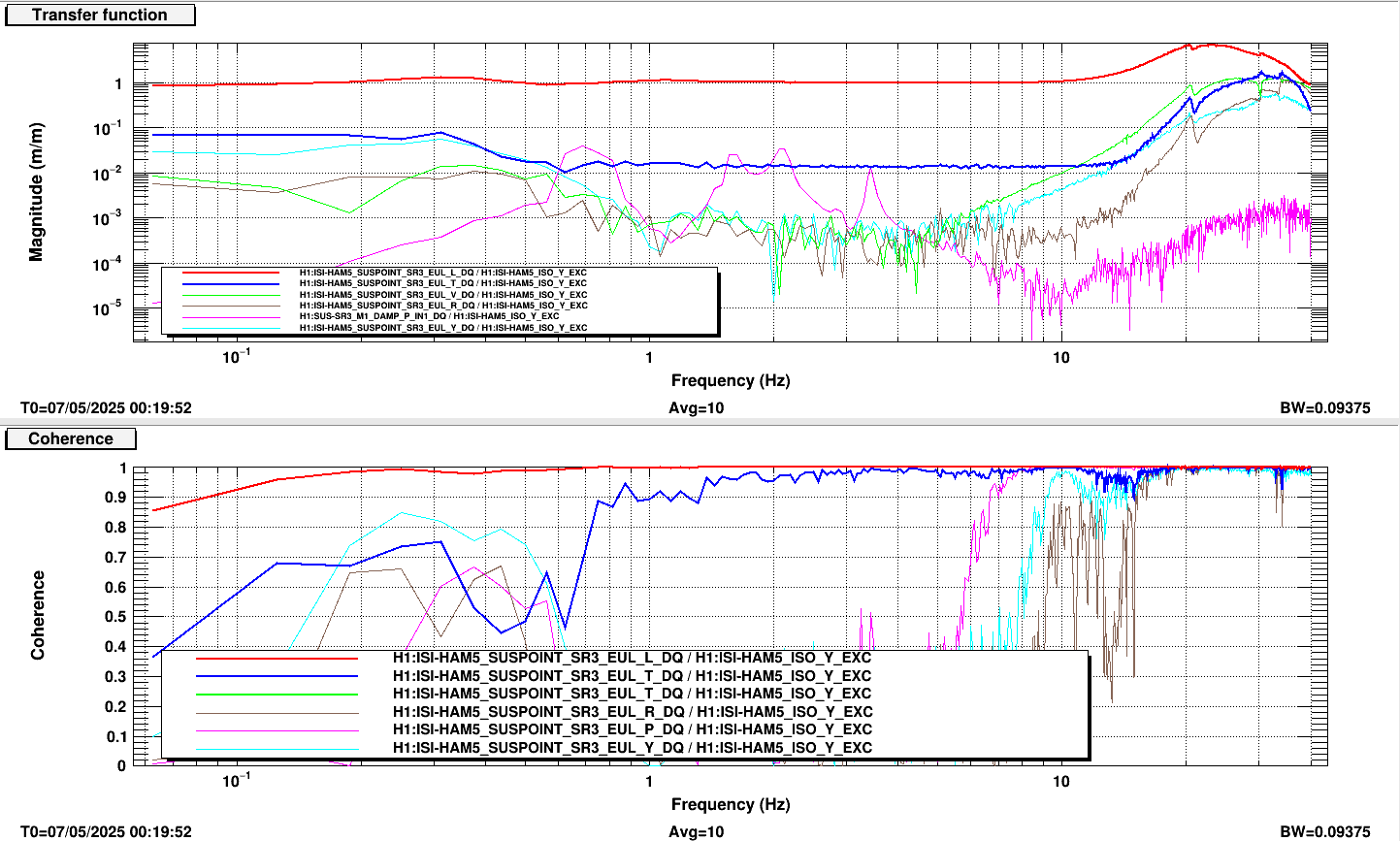
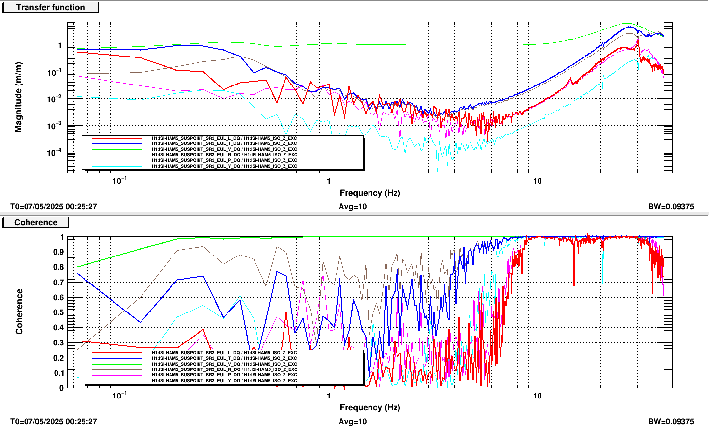
Here I post the coherence and transfer functions between the excitations of HAM5 in X, Y, and Z to the SUSPOINT degrees of freedom.
The band from 5-10 Hz seems to be low enough amplitude that I think we can claim that the drives are clean enough in the SUSPOINT basis to perform the calibration.
Note that the high coherence between L/T and HAM5_ISO X/Y is expected, since the SR3 euler basis does not perfectly align with the cartesian basis of HAM5.
J. Kissel (for O. Patane and E. Bonilla)
Also during this barrage of measurements, Oli and Edgard gathered Open Loop Gain (IN1/IN2), Loop Suppression (IN2/EXC), and Closed Loop Gain (IN1/EXC) tfs under the presence of DAMP_EXC.
Within the templates mentioned below, there're two data sets.
The "New OSEMINF gains" data is with with the above mentioned
H1:SUS-SR3_M1_OSEMINF_T1_GAIN 3.627
H1:SUS-SR3_M1_OSEMINF_T2_GAIN 1.396
H1:SUS-SR3_M1_OSEMINF_T3_GAIN 1.345
H1:SUS-SR3_M1_OSEMINF_LF_GAIN 1.719
H1:SUS-SR3_M1_OSEMINF_RT_GAIN 1.490
H1:SUS-SR3_M1_OSEMINF_SD_GAIN 1.781
The "OG OSEMINF gains" data is with the OSEMINF gains that have been present throughout O4 (as they were reverted post-measurement)
H1:SUS-SR3_M1_OSEMINF_T1_GAIN 1.478
H1:SUS-SR3_M1_OSEMINF_T2_GAIN 0.942
H1:SUS-SR3_M1_OSEMINF_T3_GAIN 0.952
H1:SUS-SR3_M1_OSEMINF_LF_GAIN 1.302
H1:SUS-SR3_M1_OSEMINF_RT_GAIN 1.087
H1:SUS-SR3_M1_OSEMINF_SD_GAIN 1.29
The raw .xmls for both these data is
/ligo/svncommon/SusSVN/sus/trunk/HLTS/H1/SR3/SAGM1/Data/
2025-05-21_1800_H1SUSSR3_M1_WhiteNoise_L_0p02to50Hz_OpenLoopGainTF.xml
2025-05-21_1800_H1SUSSR3_M1_WhiteNoise_P_0p02to50Hz_OpenLoopGainTF.xml
2025-05-21_1800_H1SUSSR3_M1_WhiteNoise_R_0p02to50Hz_OpenLoopGainTF.xml
2025-05-21_1800_H1SUSSR3_M1_WhiteNoise_T_0p02to50Hz_OpenLoopGainTF.xml
2025-05-21_1800_H1SUSSR3_M1_WhiteNoise_V_0p02to50Hz_OpenLoopGainTF.xml
2025-05-21_1800_H1SUSSR3_M1_WhiteNoise_Y_0p02to50Hz_OpenLoopGainTF.xml
The open loop gain transfer functions (IN1/IN2) have already been exported
/ligo/svncommon/SusSVN/sus/trunk/HLTS/H1/SR3/SAGM1/Data/
2025-05-21_1800_H1SUSSR3_M1_WhiteNoise_?_0p02to50Hz_OpenLoopGainTF_tf.txt << exports of "OG OSEMINF gains" data
2025-05-21_2000_H1SUSSR3_M1_WhiteNoise_L_0p02to50Hz_OpenLoopGainTF_tf.txt << exports of "New OSEMINF gains" data
Also, I've exported the loop suppression of the "OG OSEMINF gains" data as
/ligo/svncommon/SusSVN/sus/trunk/HLTS/H1/SR3/SAGM1/Data/
2025-05-21_1800_H1SUSSR3_M1_WhiteNoise_?_0p02to50Hz_OLGTF_LoopSuppression_tf.txt << exports of "OG OSEMINF gains" data
Jeff, Oli
Looking into (1) from 84462.
Before this vent, although the cable pinouts were flipped for both RMs, the phase for the TFs were at 0. Now that the cables have been flipped (fixed), we are seeing that the closeout transfer functions that I took 84498 are showing that the phase for the RMs is now flipped, at 180. Additionally, both RMs are still needing the damping sign to be +1, instead of the usual -1.
Since there does still seem to be a sign issue somewhere in the sensor chain for RM2, we would have expected the 'after' transfer function phases to differ between RM1 and RM2, so it's strange that they both have switched over to 180.
I've attached the transfer functions for RM1 and RM2 comparing the after vent measurements to the last measurements we had done for them with damping loops off, which was in 2022.
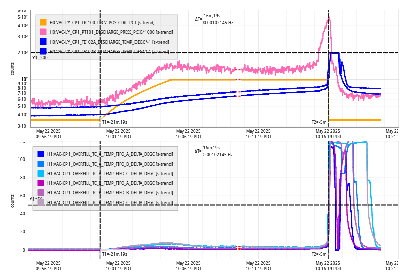
Thu May 22 10:16:19 2025 INFO: Fill completed in 16min 15secs
Patrick, Jonathan, Dave:
MC2 camera went offline at 06:30 today, this was another instance of the new software eventually running into the 1024 limit for open files. This process is on h1digivideo4 and surprisingly had only been running for 8 days.
Jonathan increased the file limit on this machine to 40,000 and we restarted the process. MC2 h1cam07 did not need a power cycle.
Summary: adding a digital offset to get a flat sensing function does not correspond to SRM detuning phase of 90, as modeled in FINESSE.
recap: I have modeled the SRCL DOF detuning due to mode mismatch. Nominally, we want the detuning phase of the SRM to be ø = 90˚ for resonant sideband extraction conditions, where there are no optical spring effects. However, mode mismatches affect this phase, and consequently we can see optical spring effects showing up in the DARM sensing function.
On site, after locking we can add a digital offset to the SRM phase to flatten the sensing function, but then the question is “does the digital offset that flattens the DARM sensing function correspond to ø = 90˚?”
And the answer is “no”, at least as modeled in FINESSE.
I have added an offset to SRCL and looked at the corresponding sensing function, and it is clear that a ø = 90 is not necessarily a flat response (starting from 5 Hz), as the plot attached shows.
In this case I’m looking at the RF readout (from DARM to AS45_Q), and where the average mismatch between all cavities is 0.01% (the start locking point is ø = 90.03˚). This also demonstrates that even a tiny mismatch can show optical spring effects.
TITLE: 05/22 Day Shift: 1430-2330 UTC (0730-1630 PST), all times posted in UTC
STATE of H1: Planned Engineering
OUTGOING OPERATOR: None
CURRENT ENVIRONMENT:
SEI_ENV state: MAINTENANCE
Wind: 11mph Gusts, 6mph 3min avg
Primary useism: 0.03 μm/s
Secondary useism: 0.09 μm/s
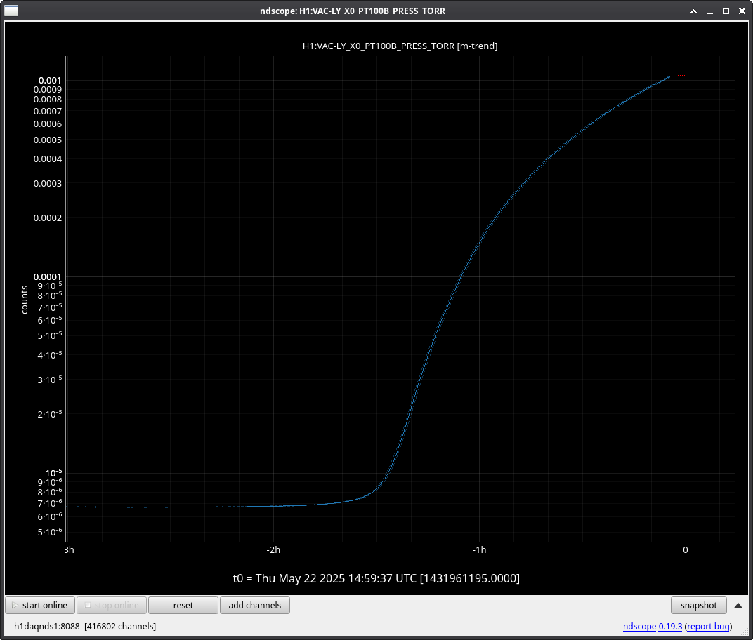
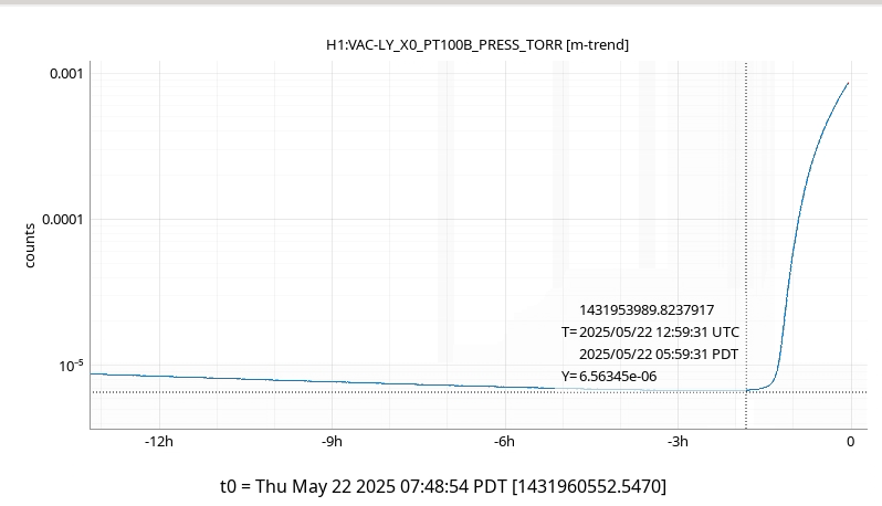
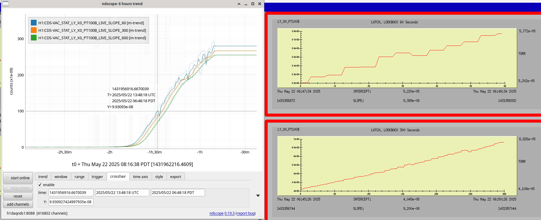
QUICK SUMMARY: HAM1 pumping continued overnight, but starting about 1.5 hours ago the pressure started rapidly climbing. No cause determined as of yet. VAC team has been contacted.
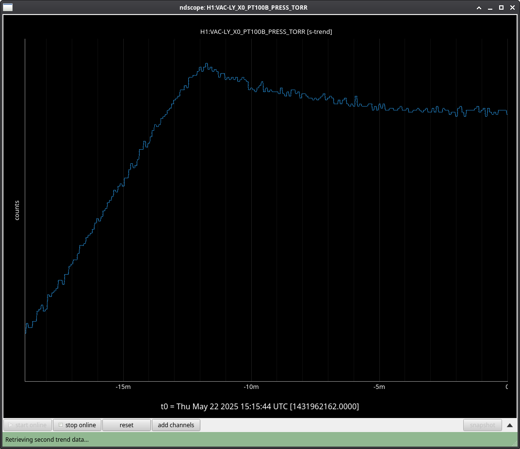
EDIT: Had the wrong channel trended, corrected in current attachment.
The gate valve on top of HAM1 was closed and the pressure is now holding; trend attached.
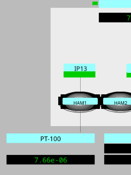
Note that we currently have a potentially confusing situation of two EPICS pressure channels for HAM1, only one of which is correct:
H1:VAC-LY_X0_PT100B_PRESS_TORR Is the correct channel, current value 1.3e-05
H0:VAC-LY_X0_PT100B_PRESS_TORR Is NOT the correct channel, unfortunately is misreports a better vacuum than we have, current value 1.5e-07
I went through all the vacuum MEDM screens and replaced the "H0" channels with the "H1" where ever I found them. Old MEDMs may still have the wrong value.
Vacuum FOM (nuc22) updated to new HAM1 gauge.
I've edited the caqtDM UI file for the Vacuum FOM to correct the HAM1 PT100B channel and remove the PT100A entry.
Troubleshooted, see here: aLog no. 84556
Starting around 6am today the vacuum pressure in HAM1, which had dropped to 6e-06 Torr, started rising rapidly. At time of typing it is up to 9.8e-04.
Richard is heading to the LVEA to investigate.
Jordan, Travis, Janos HAM1 pumpdown continued. The new Agilent leak checker is backing the turbo pump. We are waiting for the He-signal to be at least <5E-9 Torr, so we could start leak checking. After evaluating the trends, it is likely that tomorrow morning this happens. Also, regardless this happens, the Ion-pump (IP13) will be possible to be opened up. Also, an interesting note, that after achieving molecular flow in HAM1, the corner pressure suddenly decreased by ~5-6E-9 Torr, that suggests a E-3 Torrl/s gas load through the HAM1/HAM2 septum viewport O-rings, so there is indeed some communication between HAM1 and the rest of the corner. The overall pressure in HAM1 in the end of the day is ~9E-6 Torr, which aligns well with fully gutted HAM chamber pumpdown speeds in the past. The large Gate Valves, first GV7, then GV5 was opened. The fully open position was achieved at ~45 and ~47 psi, respectively. No issues were encountered during the process. The corner pressure went down quickly to ~3.5E-8 Torr. RGA scans are continuously being taken.
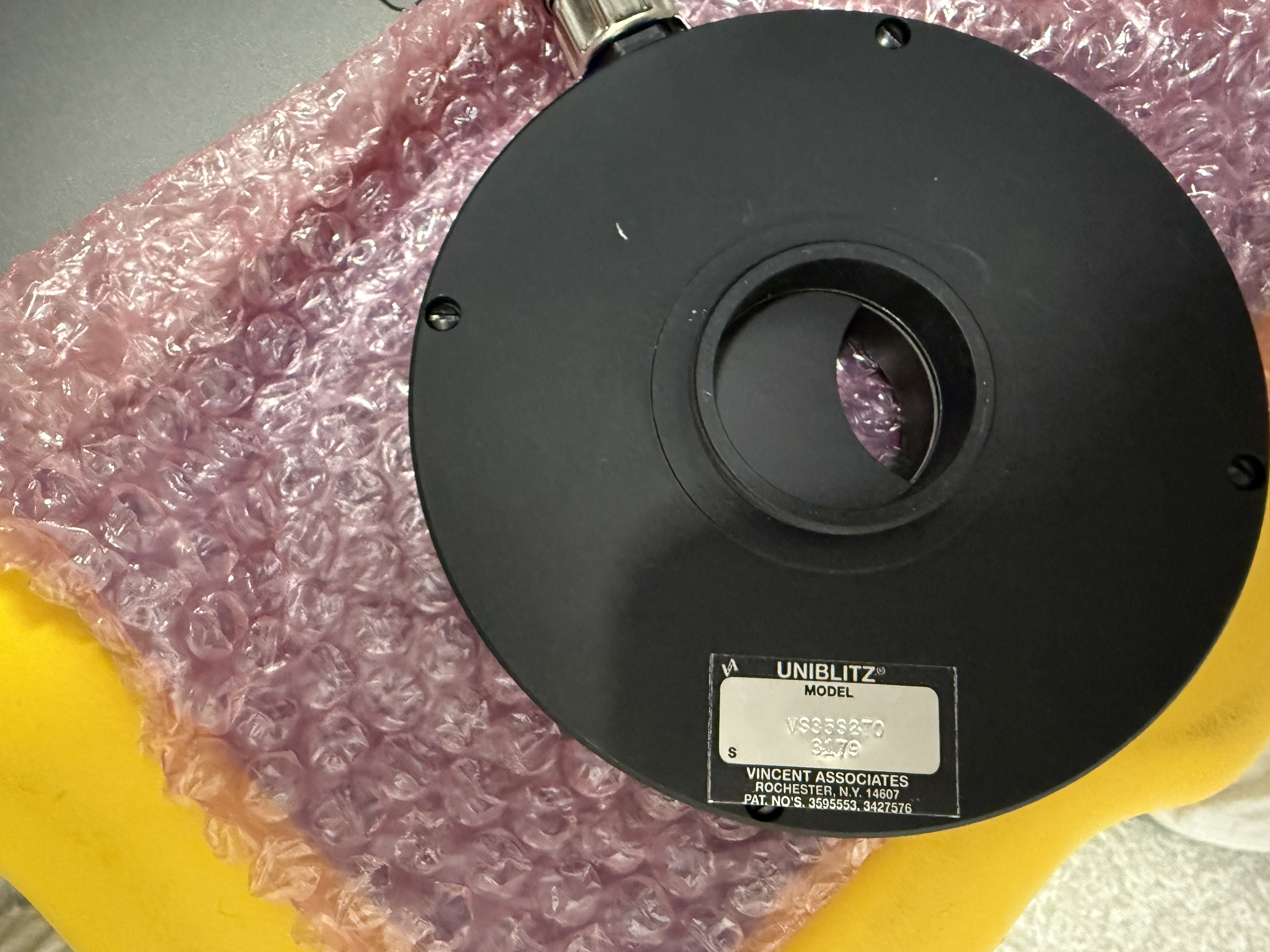
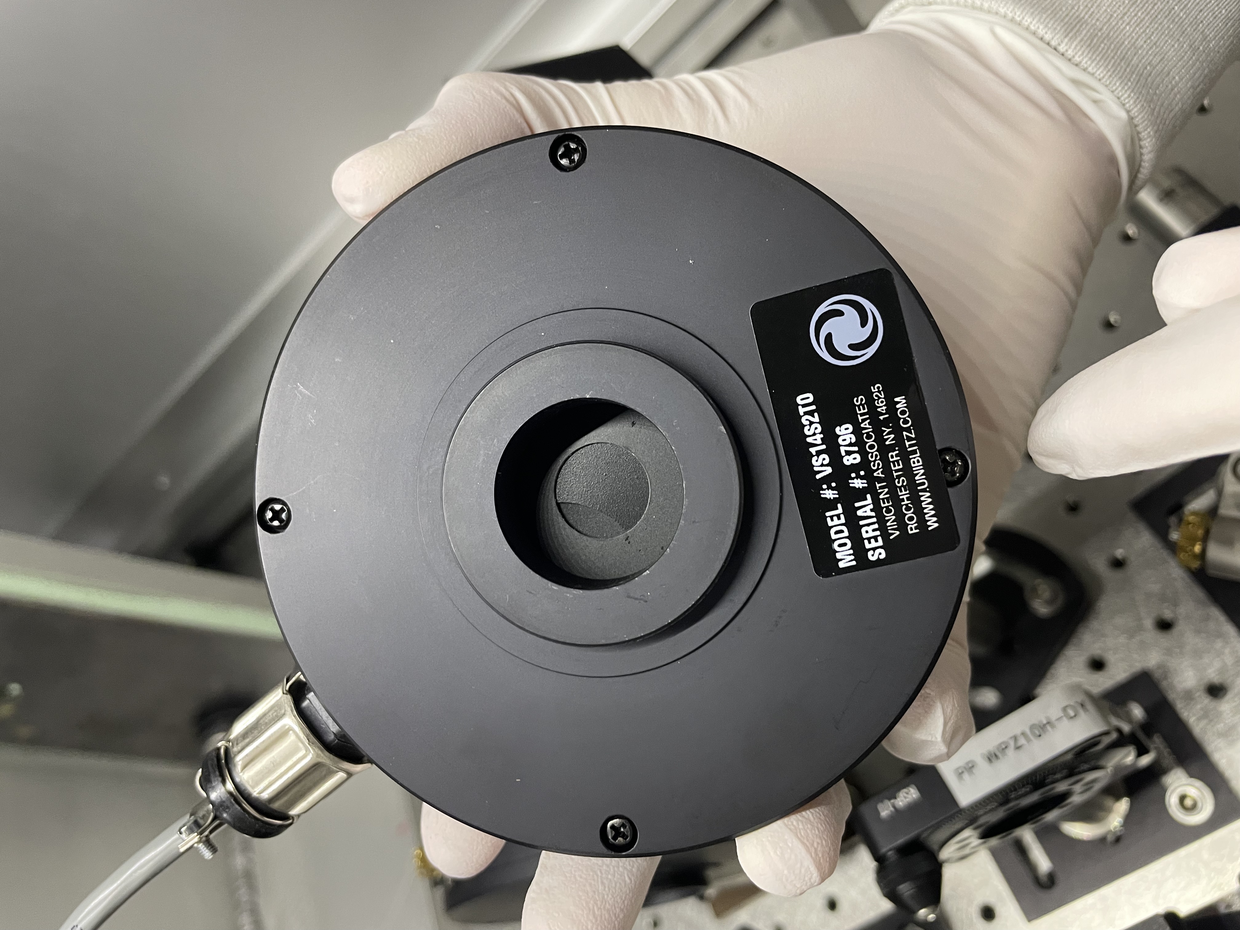
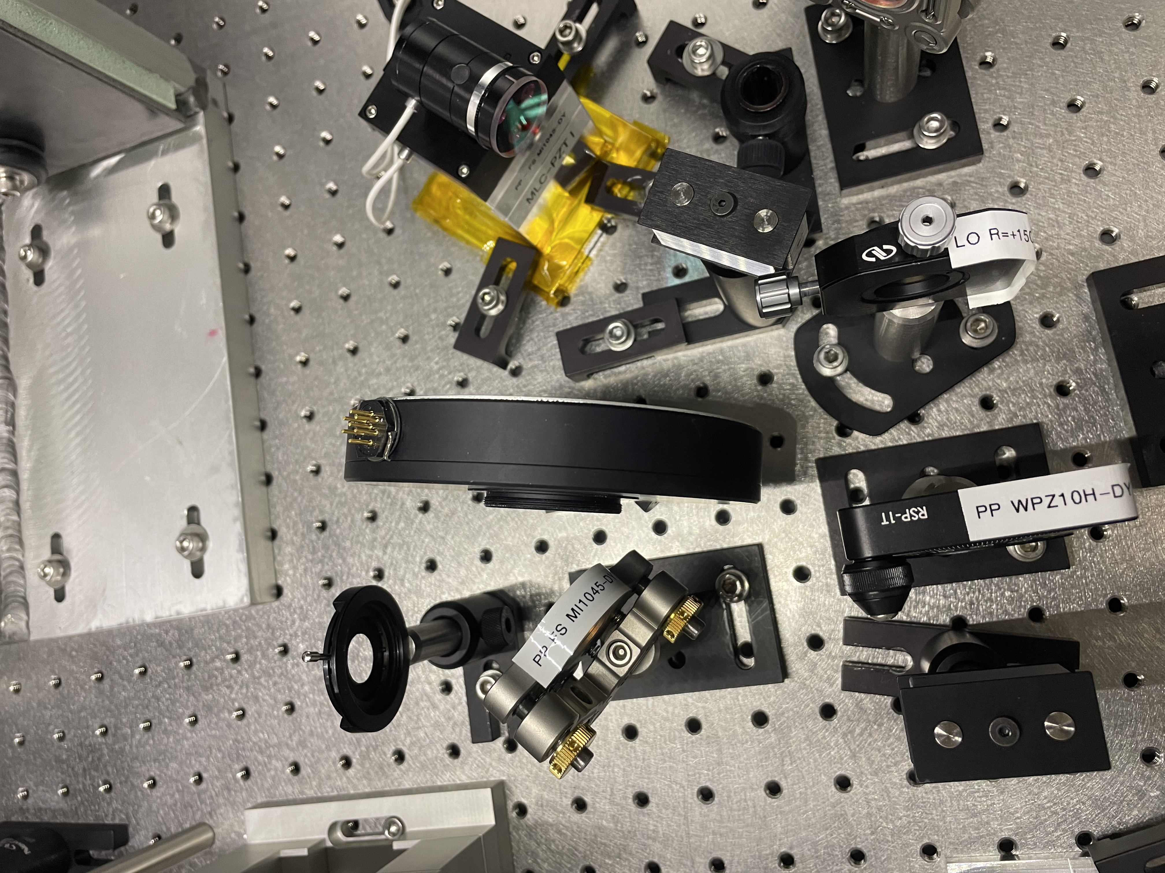
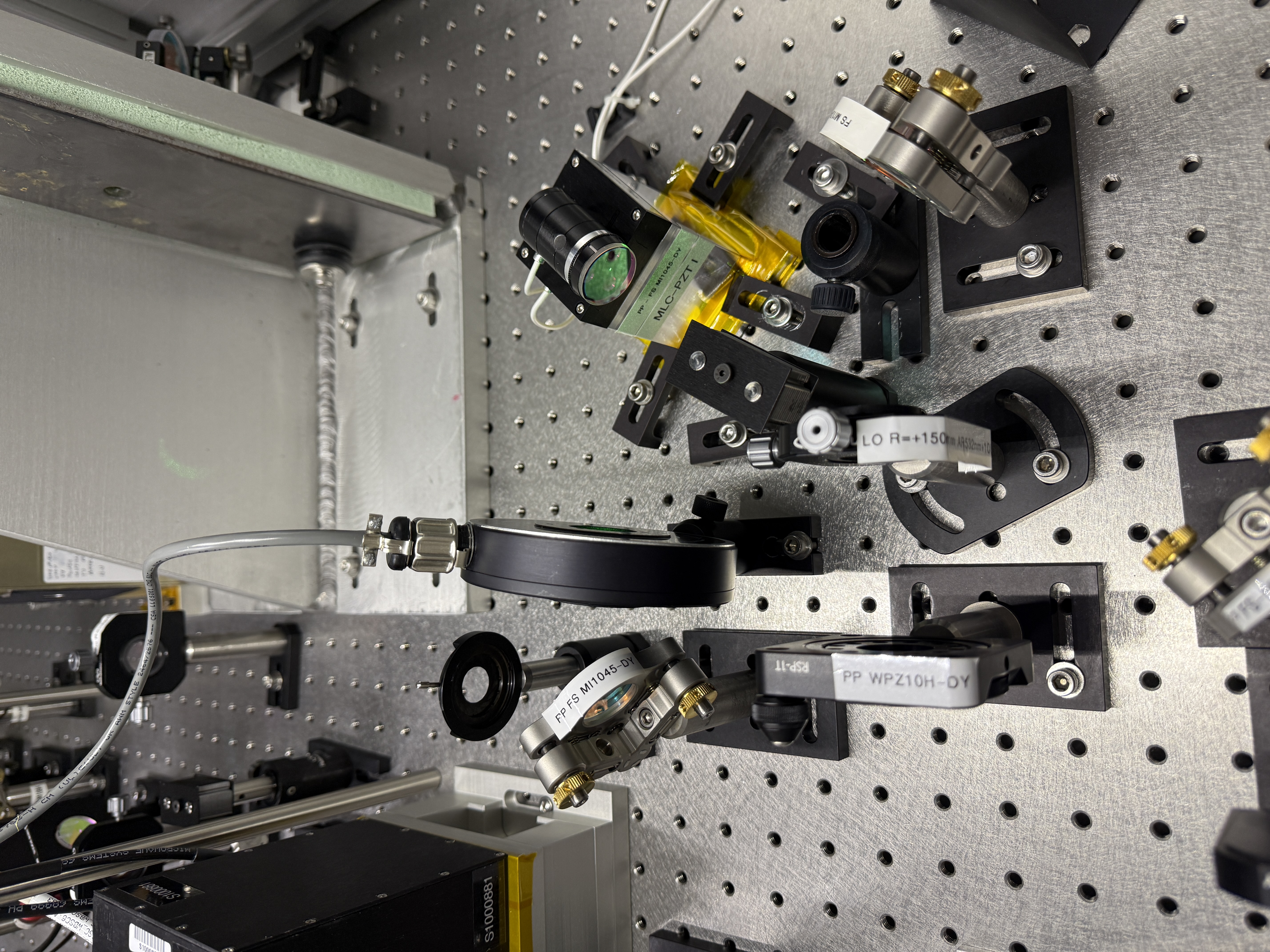
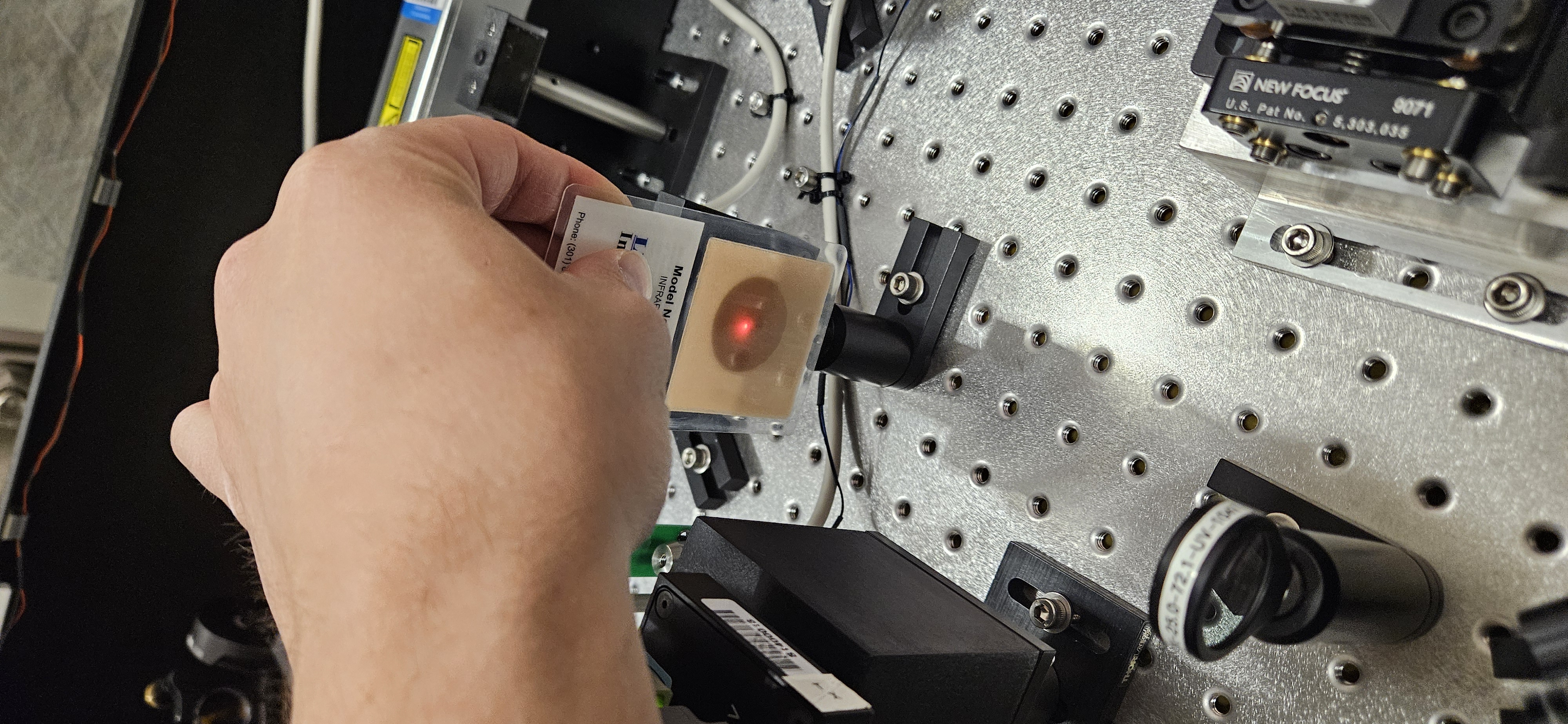
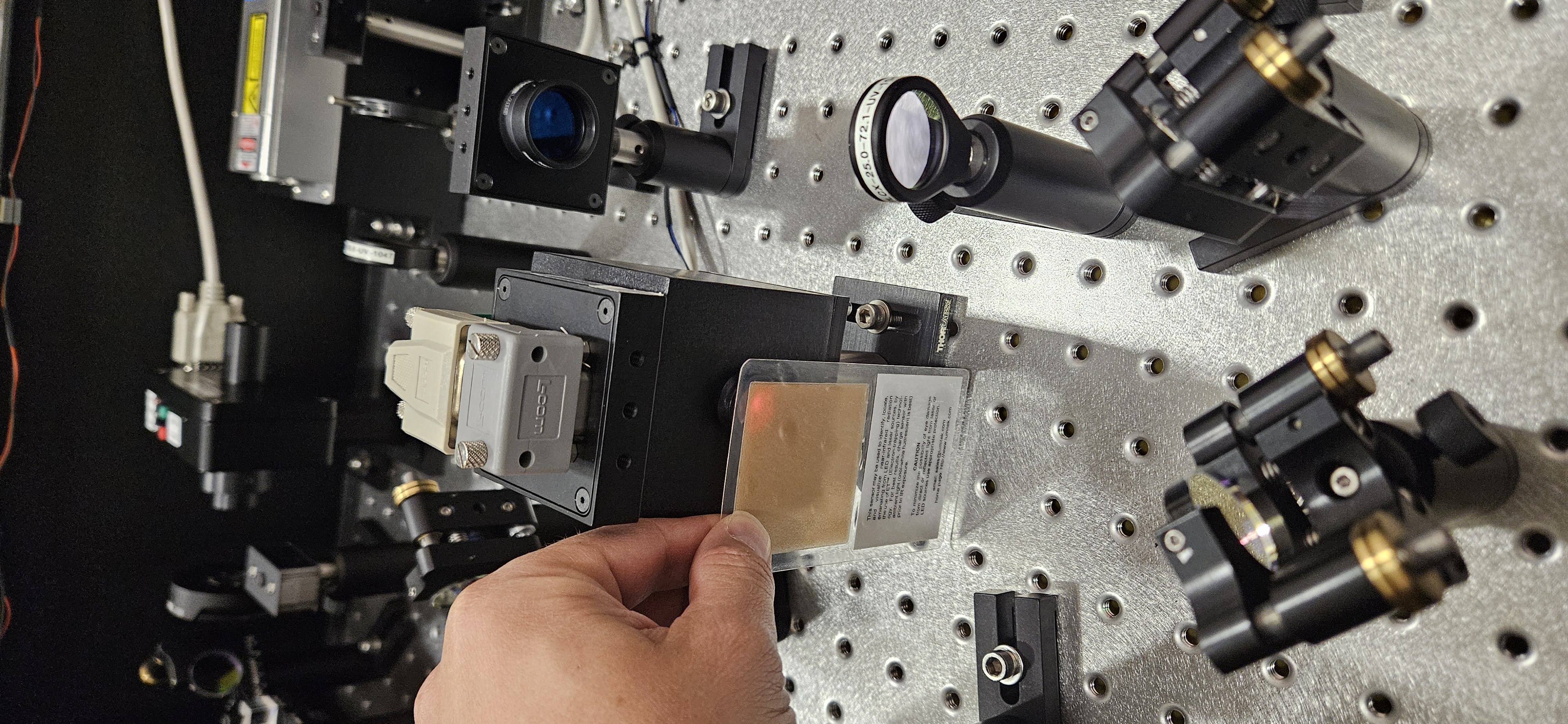
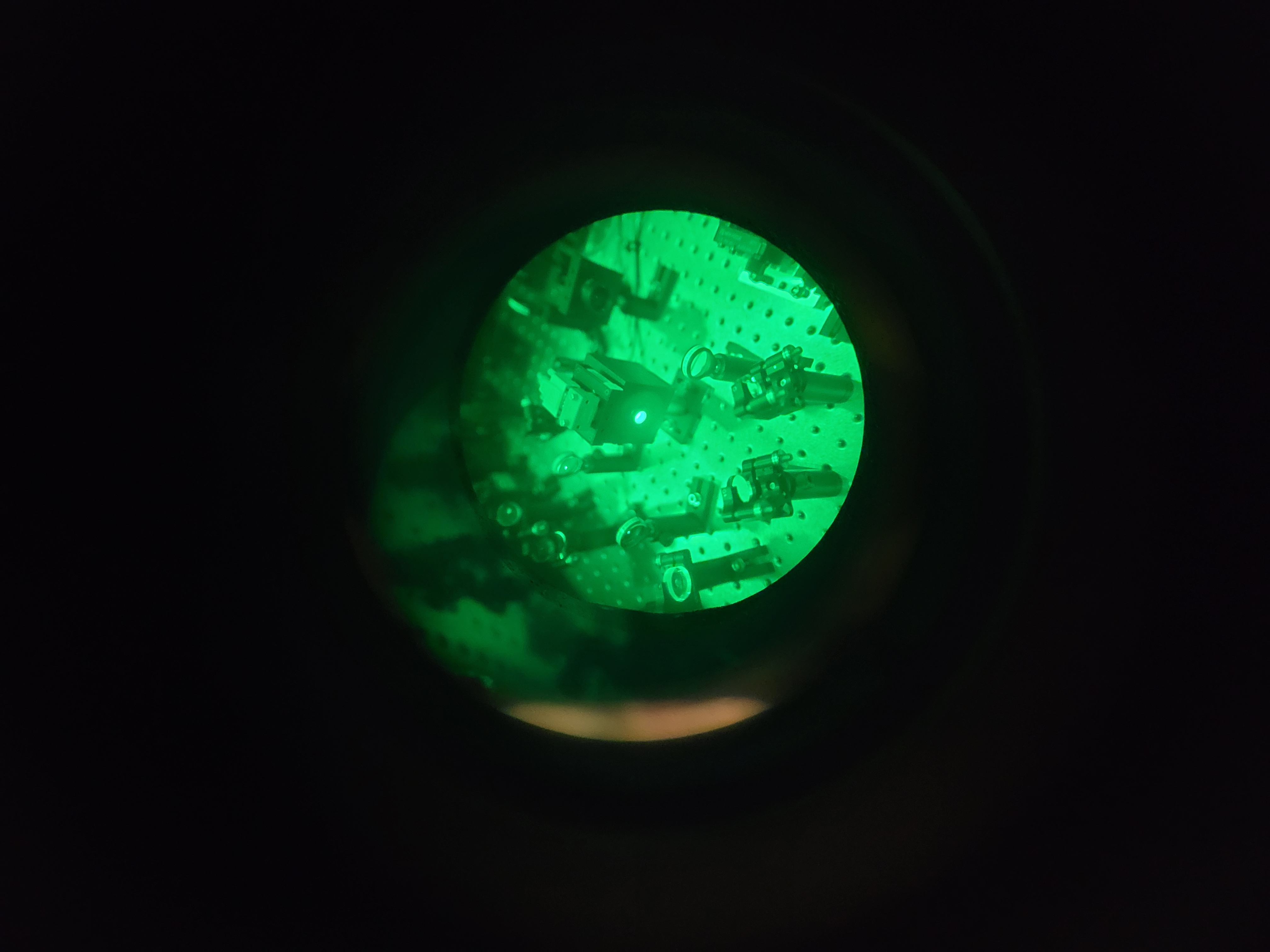
Camilla and I removed the broken Model#VS35S2T0 Serial#3179 shutter and replaced it with Model#VS14S2T0 Serial#8796. The replacement unit had a slightly smaller outer diameter so we traded some posts with beam dumps that were on the side of the table not in use to get the correct height.
Y-End TX Module Maintenance was performed today.
Everything went fairly well while following the instructions laid out in T1600436 -V12 Except the AOM Rejected Power measurement. This measurement inbetween PBSC2 and beam dump 2 is measuring the AOM power that we were dumping on to the beam dump. It didn't ever give us a static value like all the rest of the measurements. The max was a 18.5 mW jump right after the we opened the shutter. Then the power would decay down to a lower value of 13.6 mw but over several minutes. The decay rate seemed to get longer after a while. The excitations were indeed turned off. We had zeroed the low power sensor with a shuttered background measurement. I'm not sure why that seemed to not be a steady number. We ended up taking the number that seemed like it had initially asymptote to before we saw the slow fall off.
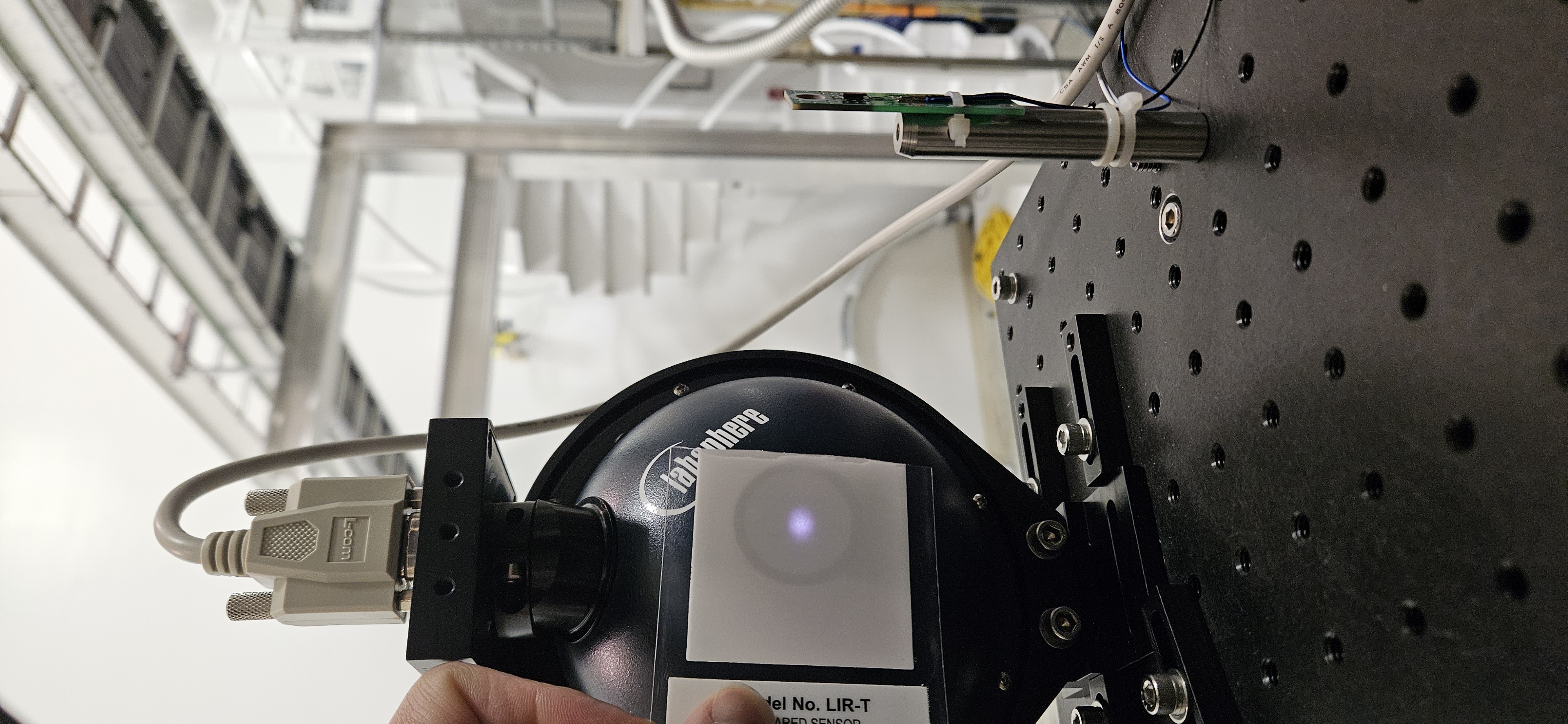
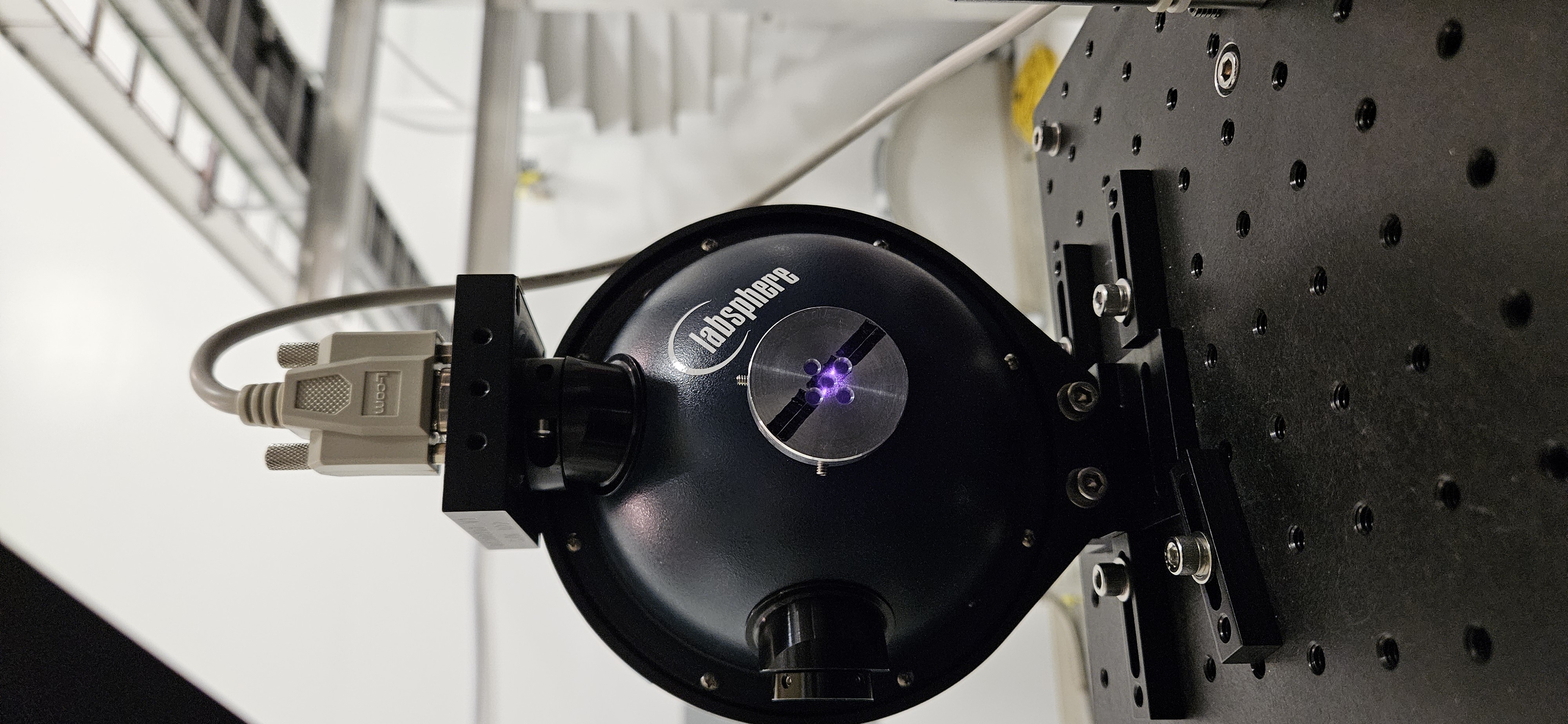
The Beam Spots all look great. TX Sphere might be very slightly to the right of perfectly center, but I think it's fine.
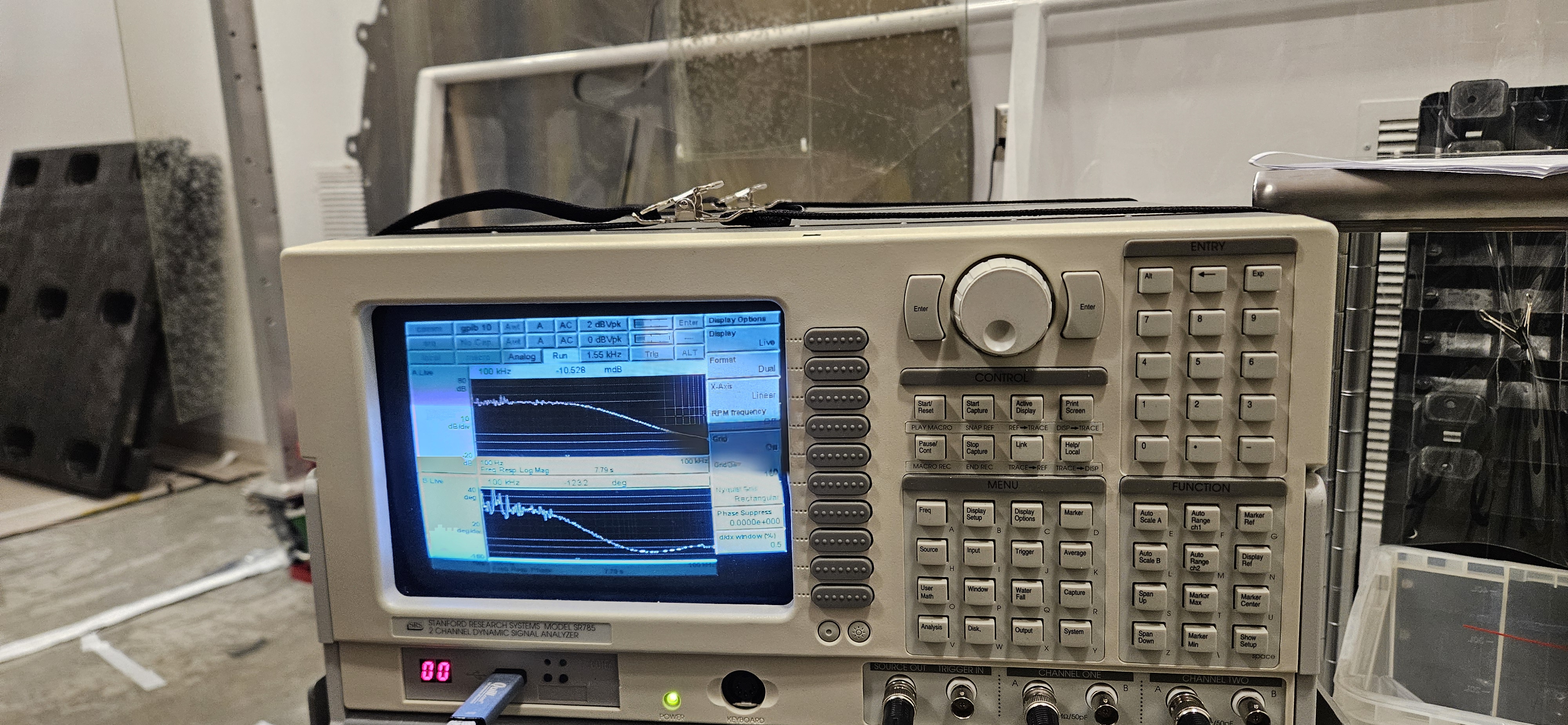
OLTF went well, Setup was well documented.
| Date | May , 21,2025 |
| Laser Shutter Check | pass |
| Max OFS Offset | 8 |
| 95% OFS Offset | 7.6 |
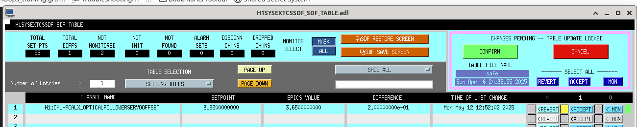
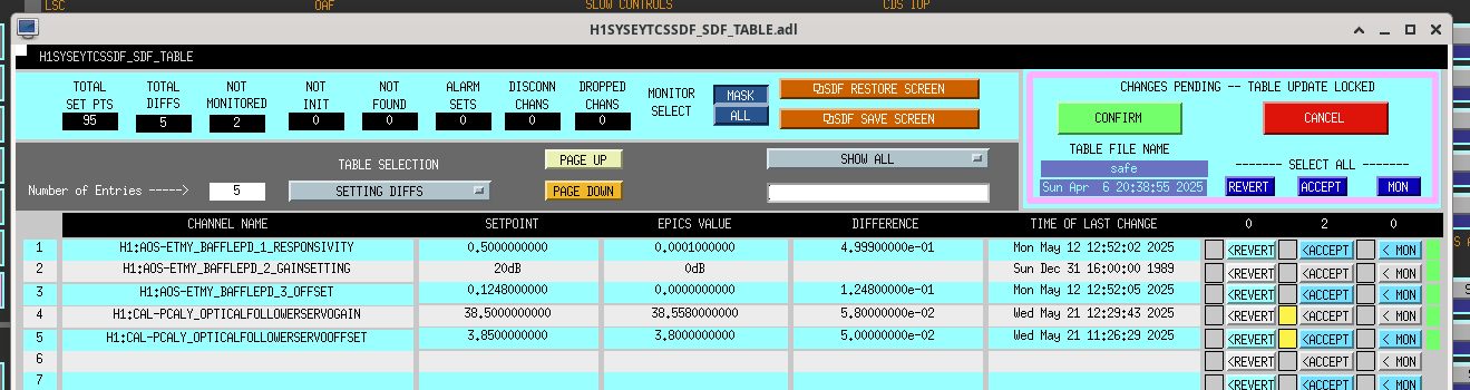
| Operating OFS Offset | 3.8 |
| Laser Output Power | 1.94 W |
| After-Laser Rejected Power | 4.11 mW |
| AOM Input Power | 1.91 W |
| Max Diffracted Power | 1.60 W |
| Un-Diffracted Power | 0.285 W |
| AOM Diffraction Efficiency | 83.77% |
| After-AOM Rejected Power | 15.5 mW |
| TxPD Power | 6.51mW |
| OFSPD Power | 6.64 mW |
| Outer Beam Power | 0.355 W |
| Inner Beam Power | 0.352 W |
| Output Beam Power Ratio | 0.991549295774648 |
| OFS Gain | 38.5 |
| OFS Phase Margin | 58 |
TITLE: 05/21 Day Shift: 1430-2330 UTC (0730-1630 PST), all times posted in UTC
STATE of H1: Planned Engineering
INCOMING OPERATOR: None
SHIFT SUMMARY: Busy day today! Arm gate valves are open, all HAM HEPI's are unlocked, and HAM1 continues to pump down. More activities below:
LOG:
| Start Time | System | Name | Location | Lazer_Haz | Task | Time End |
|---|---|---|---|---|---|---|
| 14:48 | FAC | Randy, Chris, Eric | LVEA | N | Moving HAM3 cleanroom | 17:22 |
| 14:49 | CDS | Jonathan | CER | N | Power cycling h1susb123 frontend | 14:50 |
| 14:49 | FAC | Richard | LVEA | N | Checks near output arm | 14:59 |
| 15:03 | FAC | Kim, Nellie | LVEA | N | Technical cleaning | 15:18 |
| 15:19 | FAC | Kim, Nellie | MX, MY | N | Technical cleaning | 16:56 |
| 15:24 | AOS | Betsy | LVEA | N | Checking on cleanroom crew | 15:28 |
| 15:57 | VAC | Jordan | LVEA | N | Helping with cleanroom move | 16:29 |
| 16:02 | ISC | Camilla | OptLab | N | Retrieving beam scanner | 16:09 |
| 16:10 | ISC | Camilla, Sheila, Raed | EX | YES | ALS beam profiling | 17:53 |
| 16:16 | IAS | Jason | LVEA | N | Clean up surveying equipment | 16:37 |
| 16:18 | CAL | Tony, RyanC | EY | YES | PCal module maintenance | 19:56 |
| 16:50 | VAC | Travis | LVEA | N | Vacuum checks | 17:22 |
| 16:53 | VAC | Jordan | LVEA | N | Vacuum checks | 17:22 |
| 16:56 | FAC | Kim, Nellie | LVEA | N | Technical cleaning | 17:44 |
| 17:26 | CDS | Fil | OptLab | N | In-vac cable terminating | 20:06 |
| 18:07 | AOS | Betsy | OptLab | N | Joining Fil | 20:05 |
| 18:09 | SUS | Oli | CR | N | SR3 OLTF | 20:36 |
| 18:10 | PSL | RyanS | CR | N | PMC/FSS alignment | 18:44 |
| 18:44 | CAL | TJ | EY | YES | Joining PCal team | 19:46 |
| 19:17 | TCS | Camilla | Optics lab | N | Parts inspect | 19:31 |
| 20:06 | EE | Fil | CER | N | Turning on high voltage | 20:40 |
| 20:25 | SEI | Jim, Mitchell, Randy | EX | N | Wind fence work | 22:13 |
| 20:41 | CDS | Fil | LVEA | N | HAM1 cable tray work | 22:34 |
| 21:07 | VAC | Janos, Travis, Jordan | LVEA | N | Opening arm GVs | 21:52 |
| 21:23 | CAL | Tony | PCalLab | Local | Swapping spheres | 21:32 |
| 22:33 | SEI | Jim | LVEA | N | Unlocking HEPI | 23:15 |
| 22:40 | CDS | Tony | EY | N | Checking a computer | 22:44 |
| 23:01 | ISC | Camilla, TJ | EX | YES | Swapping ALS shutter | Ongoing |
13:25:11 Wed 21 May 2025 PDT all models on h1sush7 stopped running. The SWWD to h1iopseih7 started its countdown with 100% IPC receive errors.
I set a bypass time of 999999 on h1iopseih7 to interrupt the countdown.
We first restarted all the models. This did not clear the error, and we found a PCI bus issue whereby only one of the four ADCs could be found.
As a precautionary measure we fenced h1sush7 from the Dolphin fabric.
Next we power cycled the computer. This fixed the PCI bus issues, all cards are visible and all models starting running.
I cleared the SWWDs and handed the system over to the control room.
Note, there were TIMING error flashes during this recovery time which we have not traced down.
[Wed May 21 13:25:11 2025] h1iopsush7: ERROR - An ADC timeout error has been detected, waiting for an exit signal.
[Wed May 21 13:25:11 2025] h1susauxh7: ERROR - An ADC timeout error has been detected, waiting for an exit signal.
[Wed May 21 13:25:11 2025] h1sussqzin: ERROR - An ADC timeout error has been detected, waiting for an exit signal.
[Wed May 21 13:25:11 2025] h1susfc1: ERROR - An ADC timeout error has been detected, waiting for an exit signal.
Added this crash to FRS20317