Nutsinee K. & Thomas Abbott
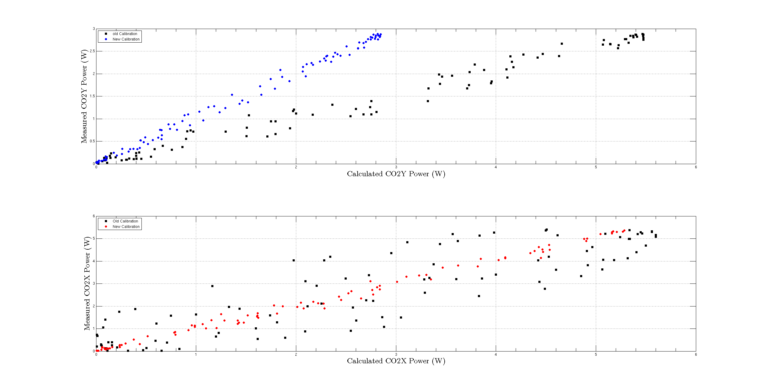
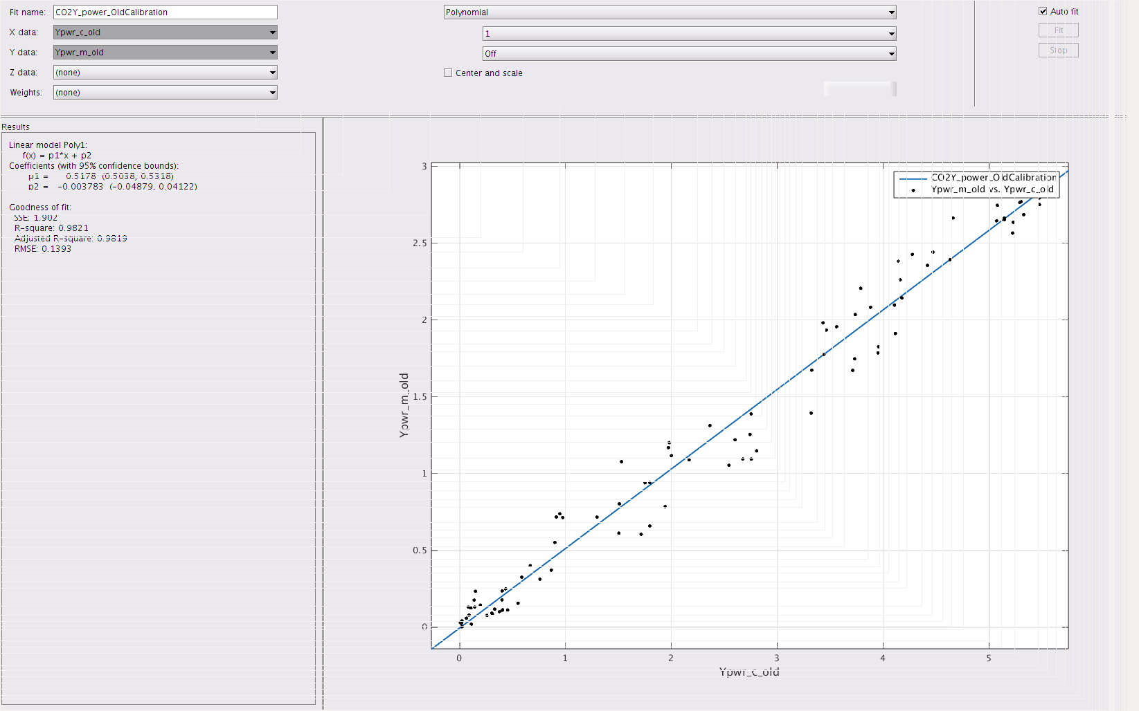
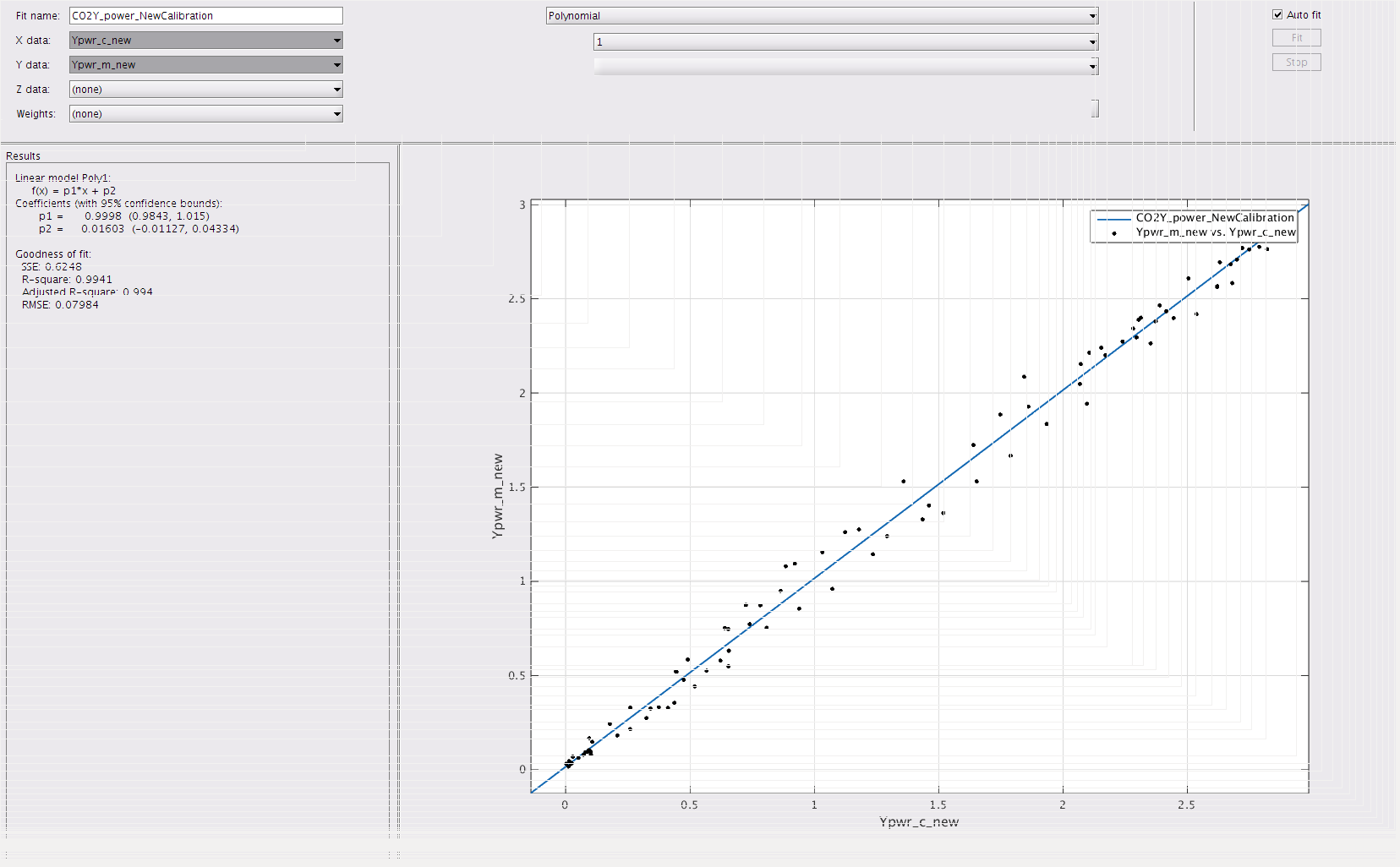
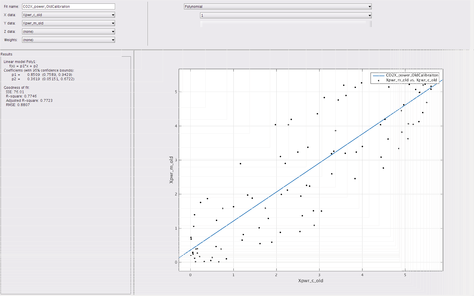
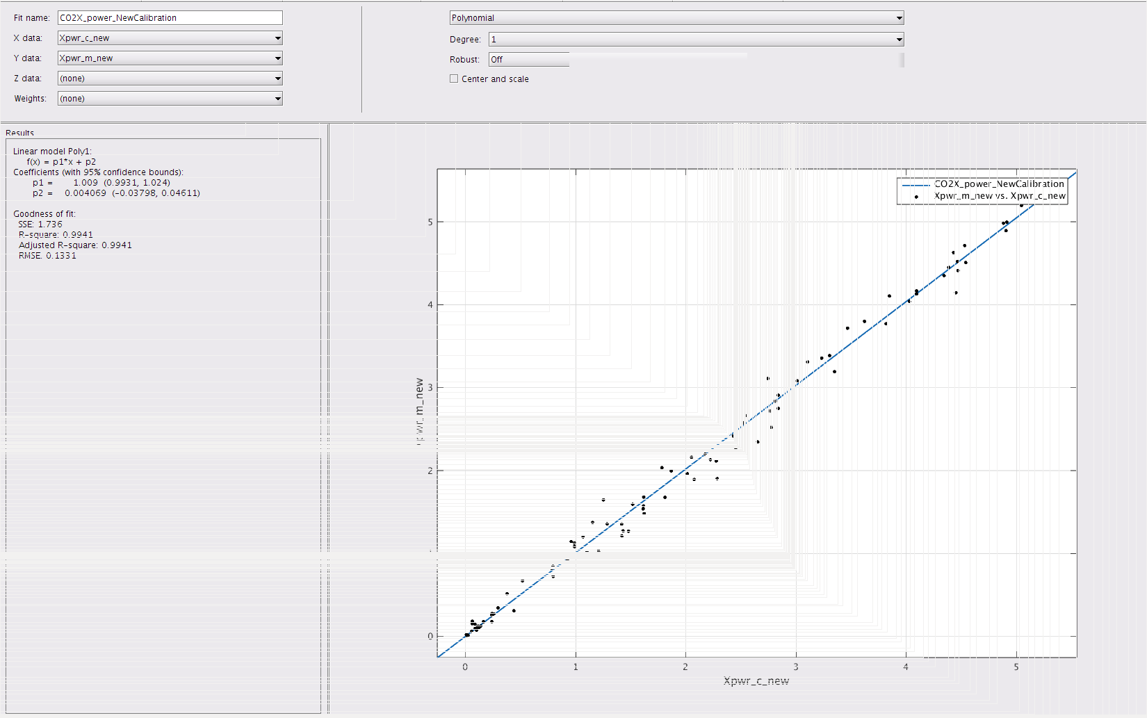
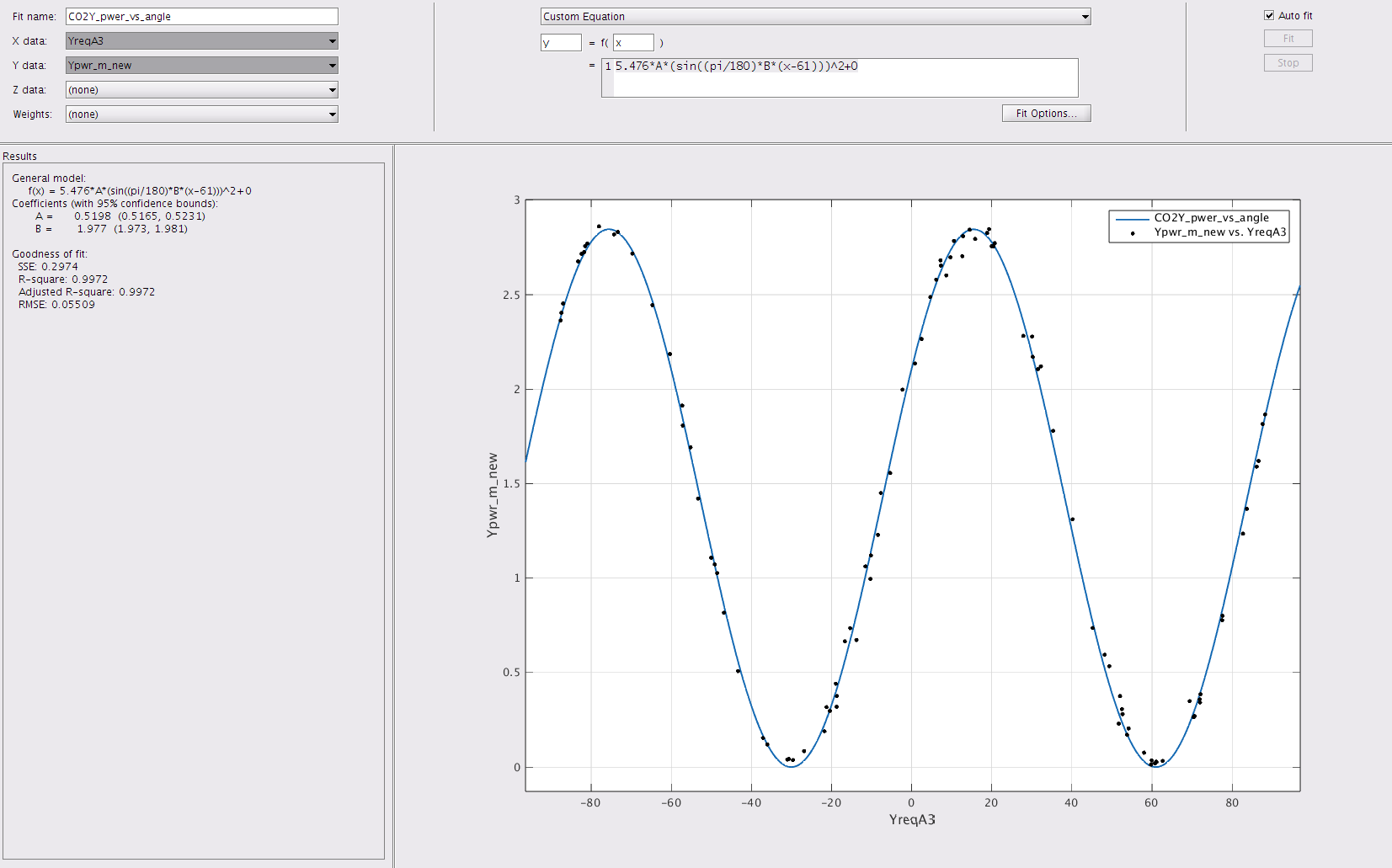
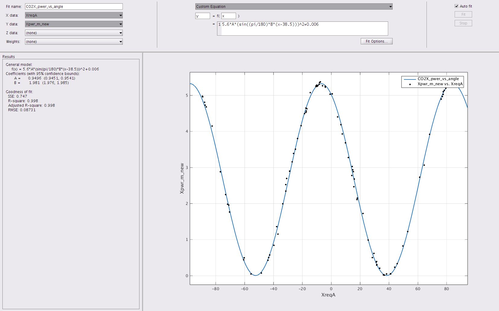
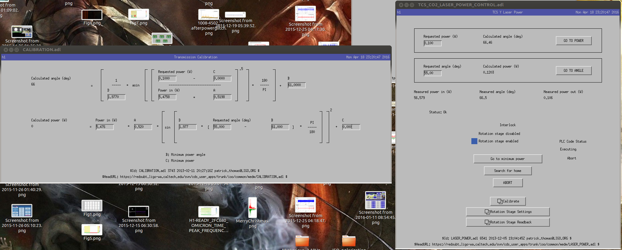
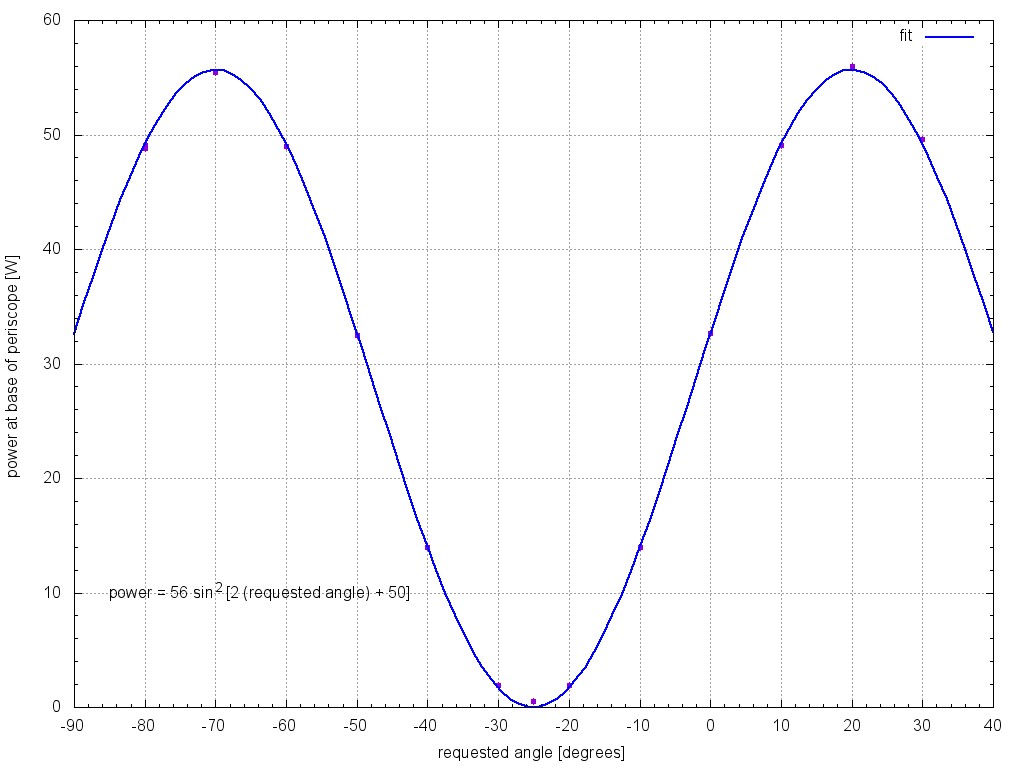
Since no one has re-calibrated the calculated power and calculated angle of the CO2 rotation stages after their performances improved so we played a little calibration game tonight. The results are attached below. Figure 1 shows the measured power vs. calculated CO2 power before and after re-calibration. Figure 2-5 show fits and improvement of calcualted vs measured power before and after the re-calibration (CO2Y power RMS improved from 0.14 to 0.08, CO2X power RMS improved from 0.88 to 0.13). Figure 6-7 show details of the fit parameters and Figure 8-9 shows the current calibration. The differences between measured power and calculated power should now agree within 0.1 W or less. Although I noticed the minimum power and the corresponding angle of CO2X can change slightly after "search for home" so if the calculated power and measured power doesn't agree within .1 this could be the reason and you would have to re-enter min angle and min power (Hint. not 0 for CO2X.).
Details:
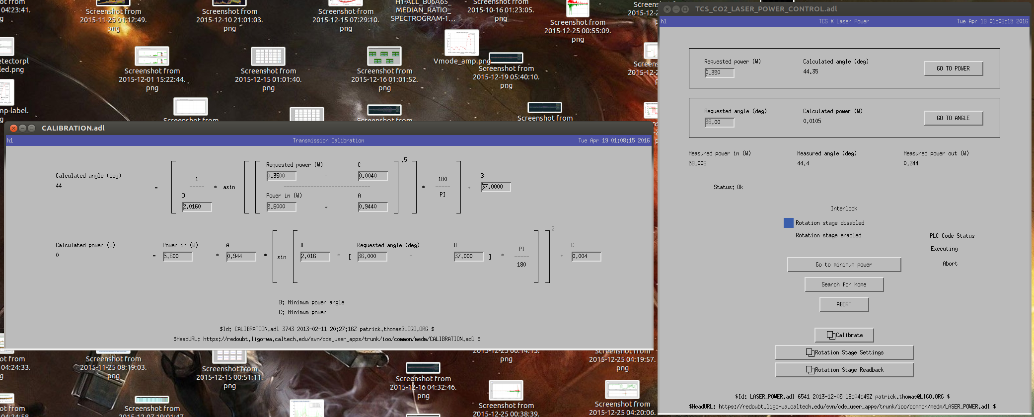
I left "Power in" variable alone since I'm not sure where the number came from (I assume this is the power going to the ITMs). Instead I changed parameter A and D according to my fits. Parameter B and C (min angle and min power) came from observations (CO2X min power never goes to 0). I wrote down the minimum power I could get to and wrote down the corresponding angle and throw them in the calibration.
Conclusion: The calculated power and measured power should agree within 0.1 W. Whether you request an angle to go to a certain power or request wanted power directly the result is the same.
I also have screenshots of the old calibrations if anyone ever needed them.