Re WP 5774 FR 4694 (PKA II 1193)
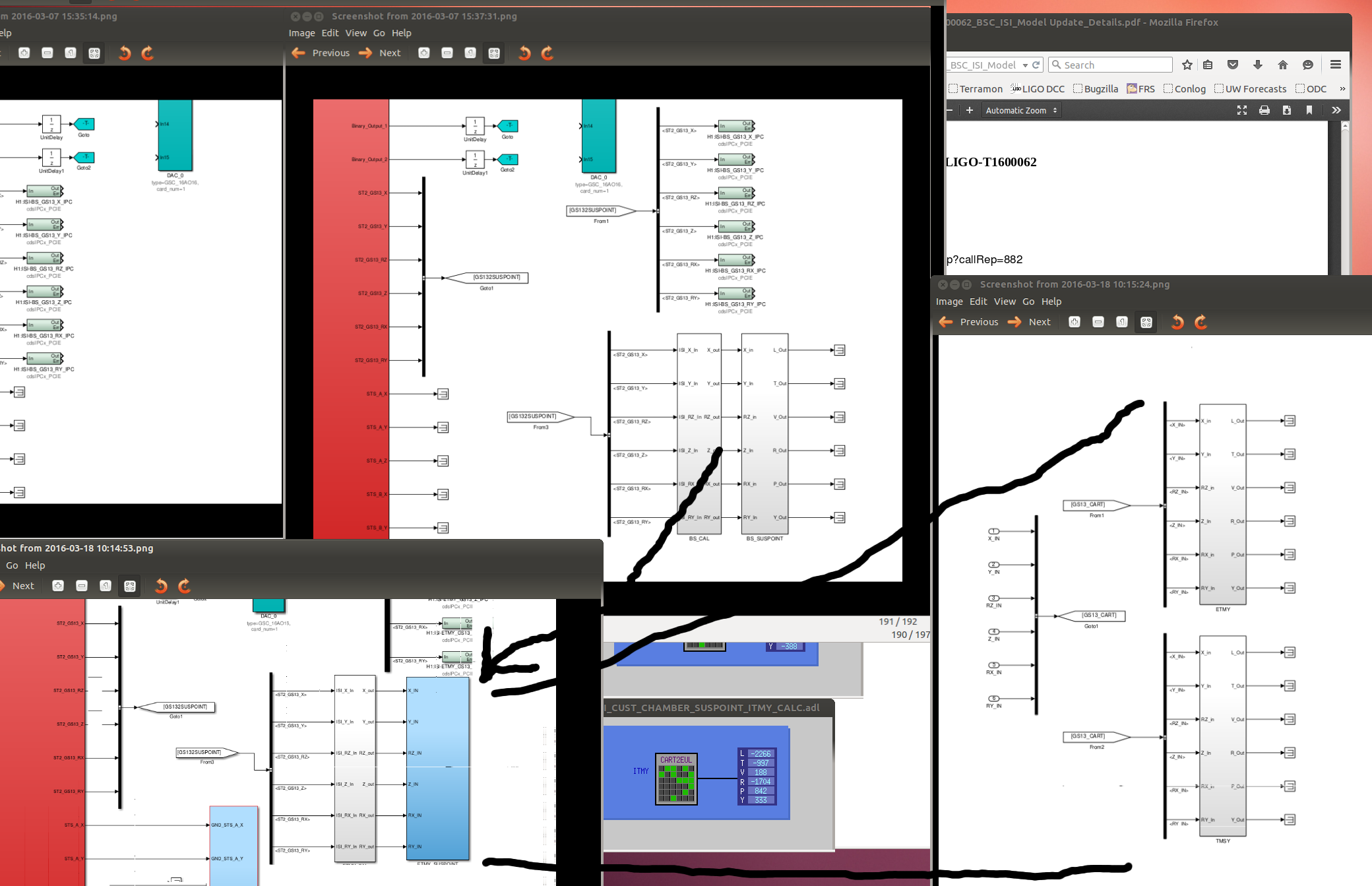
To offload the ISI witness point motion calculation from the SUS to the ISI which runs slower and has more computation headroom. See 25913 for original update to ISIs--the SUSPOINT being the important thing. Looked at comparing the calibration of the ISI motion in the SUS 16k machine vs the 4k ISI machine in LHO aLog 25993--Jeff & I may look more closely at this but we think all the differences are explainable. The original updated library parts were modified to capture the data in frames--see 26128. After restarting the ITMY model to test these changes and adapting the implementation for ISIs which have multiple suspensions (See Attached) earlier this week, yesterday, 17 March, the remainder of the BSC ISI were restarted. All restarted fine--26117.
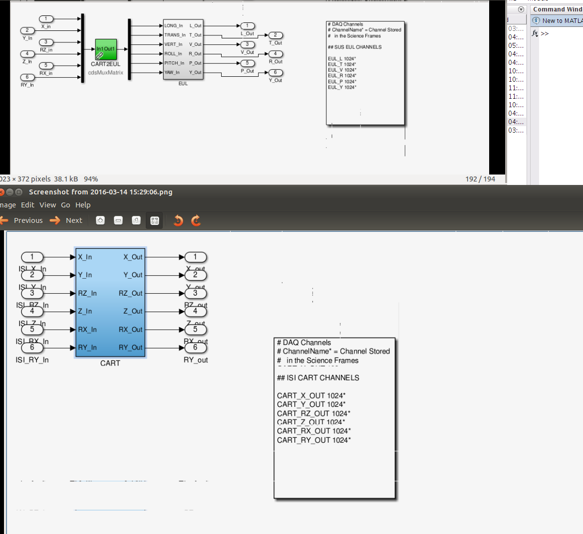
This morning, the Calibration filters have been loaded and following JK's aLog 4553, I've populated all the new BSC ISI CARTESIAN to EULER matrices.
I believe this means that DetChar can repoint the detchar plots from the SUS model to the ISI models. Once there and we are happy, the SUS calcs can be removed.
The new channels are H1:ISI-{isi}_SUSPOINT_{sus}_EUL_{euler dof}MON where
isi = ITMY BS ITMX ETMX ETMY
sus = ITMY BS ITMX ETMX ETMY TMSX TMSY [The TMS projection matrices are identical to the ETM's so there is no new info there at the moment.]
euler dof = L T V R P V
Ah ha! I see that the TMS matrices on the SUS do have values distinct from the ETMs. I will update the database
/opt/rtcds/userapps/release/isc/common/projections/ISI2SUS_projection_file.mat
to include the TMSs and correct the ISI CART2EUL TMS values shortly.