soren.schlassa@LIGO.ORG - posted 16:55, Tuesday 08 March 2016 - last comment - 17:10, Tuesday 08 March 2016(25944)
Line at 47.683Hz in stochastic O1 analysis
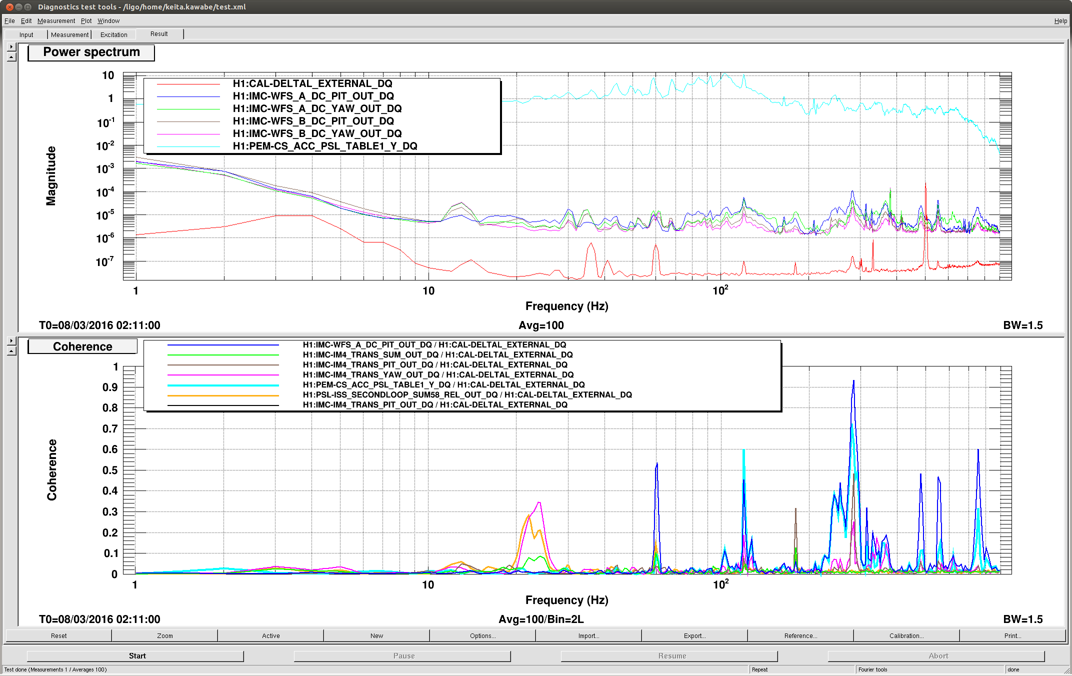
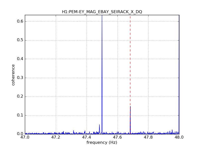
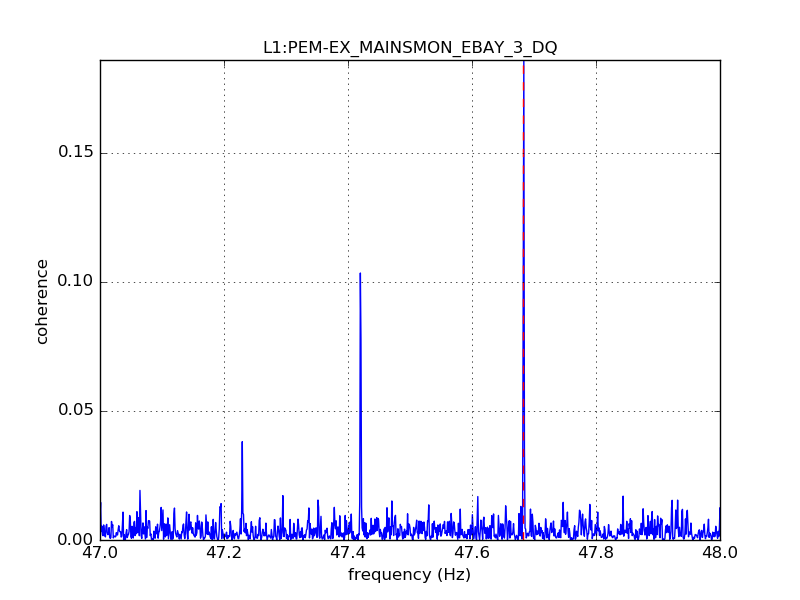
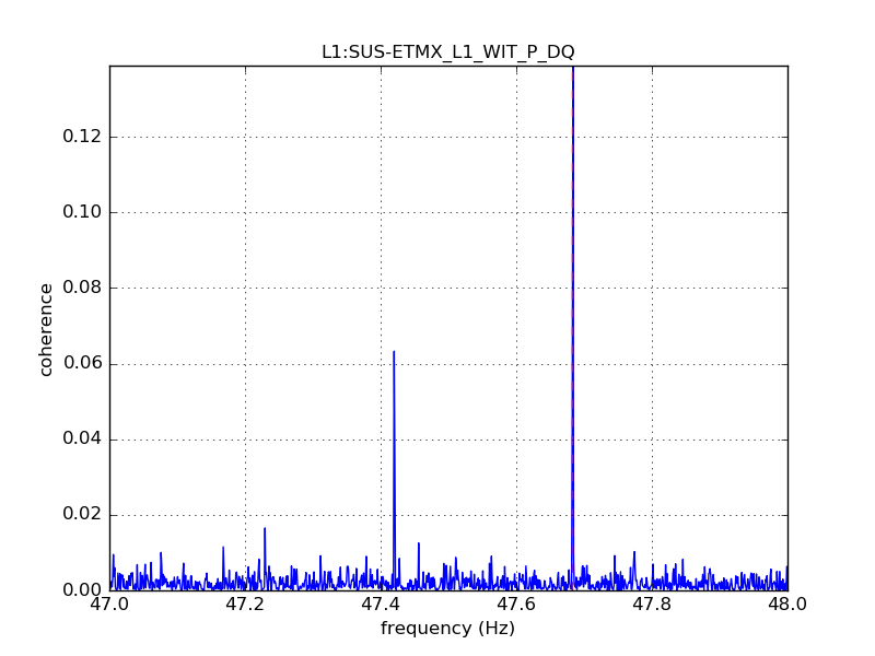
A line at 47.683 Hz has appeared in the output of the stochastic O1 (time shifted) analysis. We have used the coherence tool to search for look for the source of this line in H1 and L1.

The line at 47.683 Hz appears very clearly in H1 in the h(t) coherence with H1:PEM-EY_MAG_EBAY_SEIRACK_X_DQ (week 13 example attached) and H1:PEM-EY_MAG_EBAY_SEIRACK_Y_DQ, in weeks 12, 13, 14, 16.

It also appears clearly in the L1 h(t) coherence, apparently associated with some other lines (eg, 47.42Hz) in weeks 5-10, 14, and 16 in these channels:

L1:SUS-ETMX_L1_WIT_P_DQ (week 5 example attached)
L1:SUS-ETMX_L1_WIT_L_DQ
L1:SUS-ETMX_L1_WIT_Y_DQ
L1:PEM-EX_MAINSMON_EBAY_3_DQ (week 5 example attached)
L1:PEM-EX_MAINSMON_EBAY_QUAD_SUM_DQ
L1:PEM-EY_MAG_EBAY_SUSRACK_X_DQ
Images attached to this report
Comments related to this report
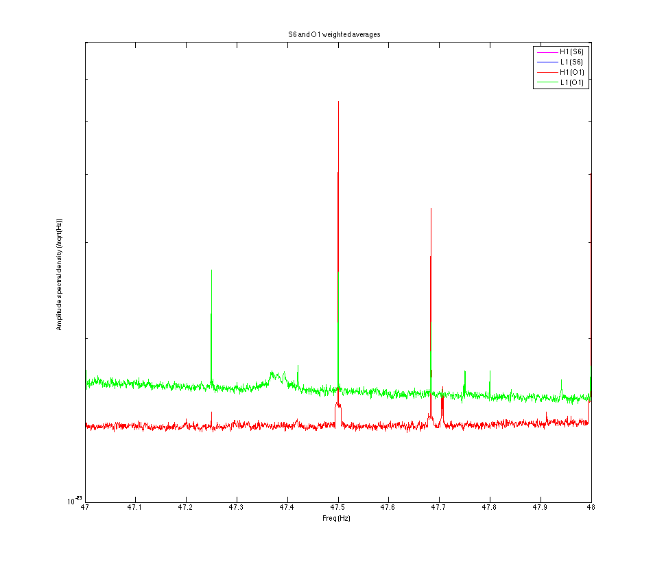
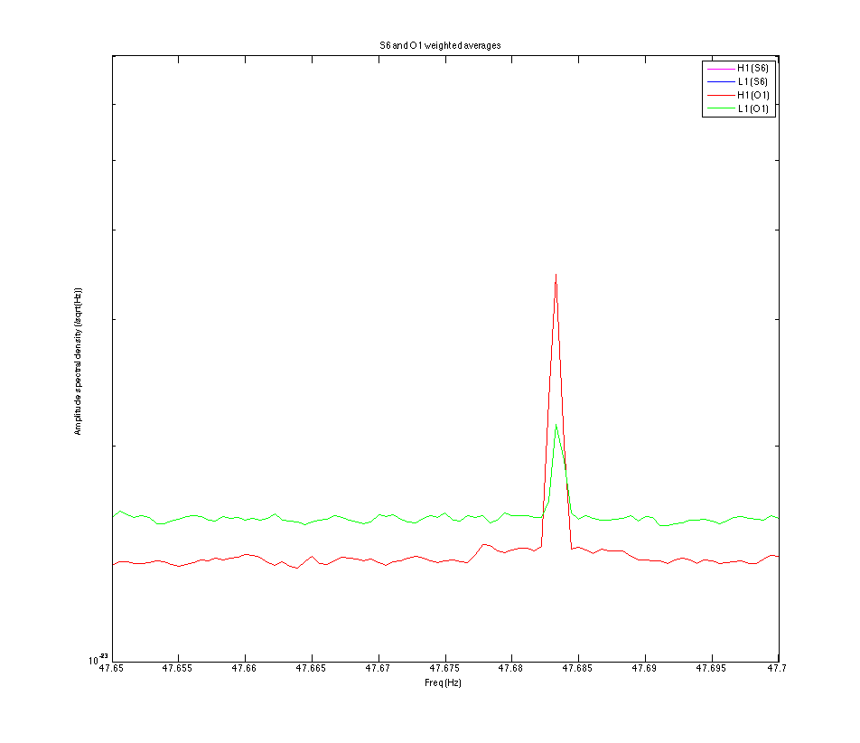
These lines are also visible in the run-averaged spectra for H1 and L1.
See attached figures (ignore the S6 labels in the legend, corresponding
to traces that are off-scale).

Can anyone think of a device, common to both observatories, that
produces such a frequency, e.g., a flat-screen monitor?
Images attached to this comment