Hardware Watchdog Swap-Out WP5750
Hugh, Jim, Dave:
We swapped out the older HWWD units in the corner station CER and the EY CER with newer models.
The corner station CER old unit was S1301712, it was unpowered and did not have the two long DB37 cables connecting it to the ITMY top stage satellite amps. It did have both binary in/out cables attached to SUS ITMY binary chassis. We replaced with the new unit S1301708 and connected both satellite amp monitor cables. We removed the binary control line, leaving just the binary monitoring line. This unit does not control the power to the ISI coil drivers for BSC1.
The EY old unit was S1301709. It was fully operational and controlling the three ISI coil drivers. Hugh put ISI into a safe state so we could de-energize the ISI coil drivers when the HWWD was powered down. We replaced with unit S1301701. We reattached all cables except for the binary control of the HWWD from the sus model (monitoring only).
The new HWWD units have different binary monitor voltage levels (low = FAULT, high = GOOD). The HWWD status is read by the SUS QUAD model via its binary input. The new hwwd-part code is in the RCG trunk version, so rather than risk building h1susitmy and h1susetmy against trunk, I made a simple model change to invert the four input binary lines to reflect to new binary levels. Both h1susetmy and h1susitmy models were restarted, no DAQ restart was required. SVN version of new sus models = r12764.
h1guardian0 reboot
Dave:
To resync all guardian nodes with recent file changes, I elected to reboot h1guardian0 to check that all nodes start automatically. First I rebooted the machine, and the nodes did not start automatically. Second I power cycled the machine and the guardian nodes did start.
h1tcscs new SIM model parts WP5749
Aidan, Dave, Jim:
Aidan made changes to his SIM parts of the h1tcscs model. Jim and I helped in getting the new code compiled. The model h1tcscs on h1oaf0 was restarted, followed by a DAQ restart.
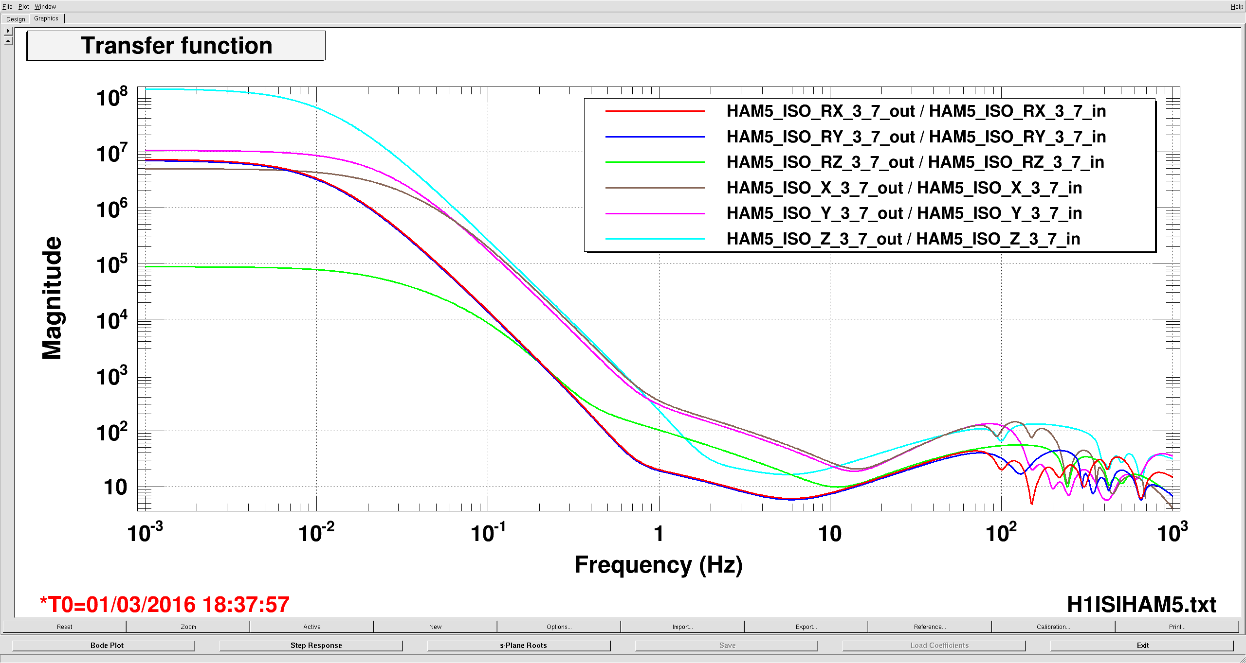
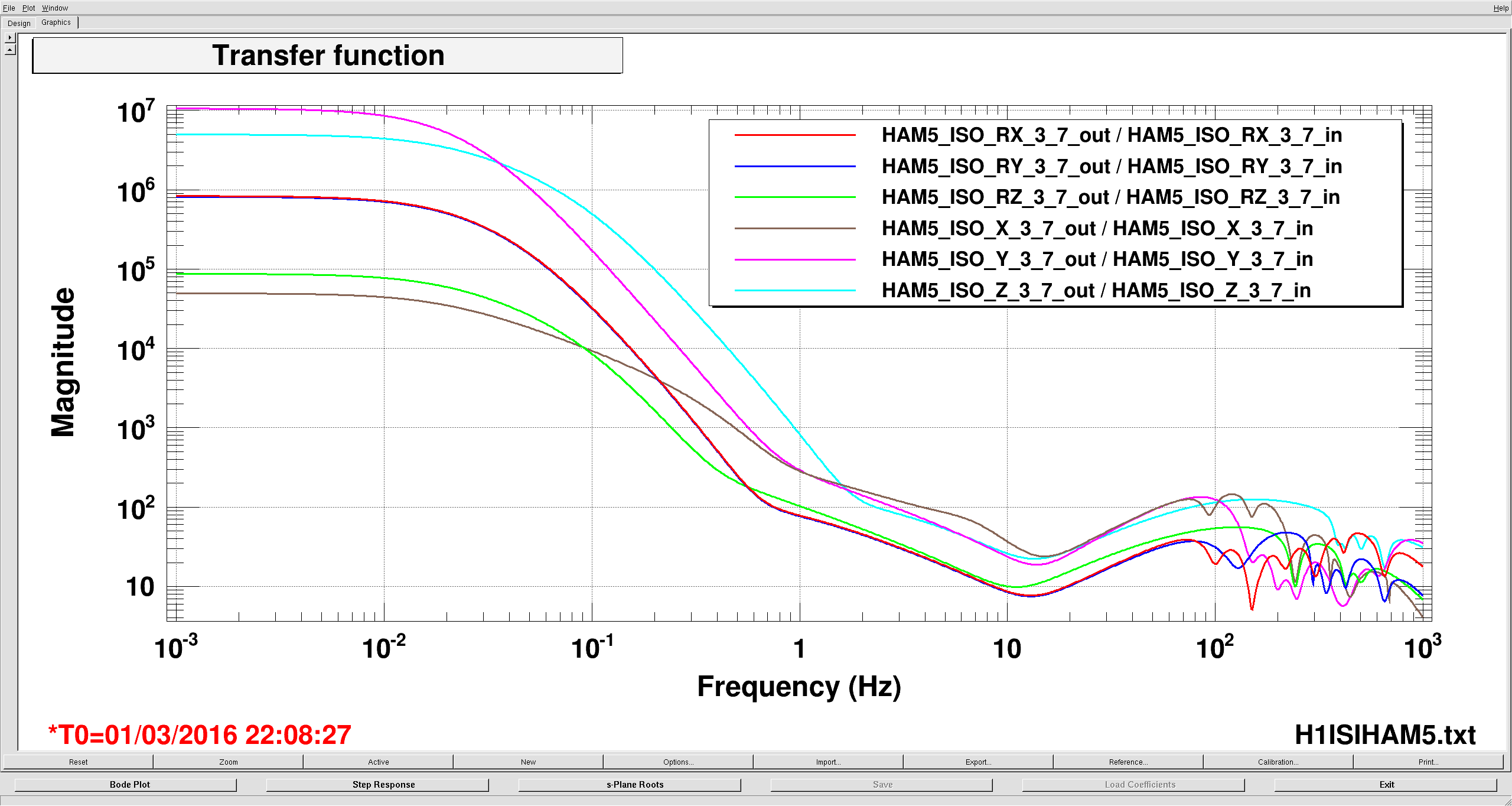
ISI HAM4,5 model change
Hugh, Jim:
the models h1isiham4 and h1isiham5 were restarted with new models. No DAQ restart was required.
Timing System IRIG-B units handling leap year
Jim:
Jim checked that our IRIG-B fanout units in MSR, EX, EY and DTS have handled this year's Feb 29th inclusion correctly, they have.
DAQ Minute trends offload from h1tw1. WP5747
Jim:
The minute trends offload from h1tw1 was completed today. During this afternoon's DAQ restart h1nds1 was configured to use the new minute trend archive.
DAQ Restart
Dave:
The daq was restarted at 15:30 to resync with the new h1tcscs model and reconfigure h1nds1 to use the new minute trends archive. This was a clean restart. h1fw0 started sufficiently in advance of h1fw1 to write a 64 second frame before h1fw1 wrote its first frame.