[Jenne, Sheila, Den, Hang, Keita]
We started the day by phasing the REFL WFS, both A and B, in both 9 and 45. In particular, we knew that the 45 MHz phasing was weird. Hang will post a reply with our detailed procedure.
We also reverted the AS 36 A&B demod phases to the values that Sheila had found on Sept 1 (alog 21083).
With this new phasing, we started trying to close WFS loops.
-
First, we used the usual AS B 36 I input matrix element for MICH pit and yaw. No other changes to MICH.
-
Then we used the usual difference between REFL 9 I A&B for INP1 pit and yaw. No other changes to INP1.
-
Next up was PRC2. We removed the REFL45 input matrix elements from both pitch and yaw, but left the usual sum of REFL 9 I A&B. PRC2 could certainly use speeding up, but we tried once by removing the -14dB in FM4 for both pitch and yaw, and then engaging the loops, but we lost lock immediately. More work for this loop in the future.
-
We closed PRC1 with no changes to the input matrix.
-
We didn't close SRC1, but we found an oddity that AS A 36 I is the dominant error signal for Pitch if we move either SRM or SR2, and AS B 36 I is the dominant signal for Yaw if we move either SRM or SR2. Seems a little weird, but was true even after we re-double-checked our AS 36 A phasing, and was true for motion of 2 different optics, so it seems real.
We captured the state of the ASC in a snapshot (saved in the same folder as the SDF's snap files), and then reverted everything to the down.snap file so that noise hunting work can happen tonight.
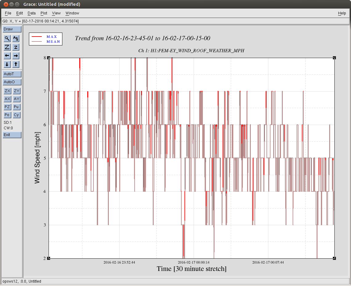
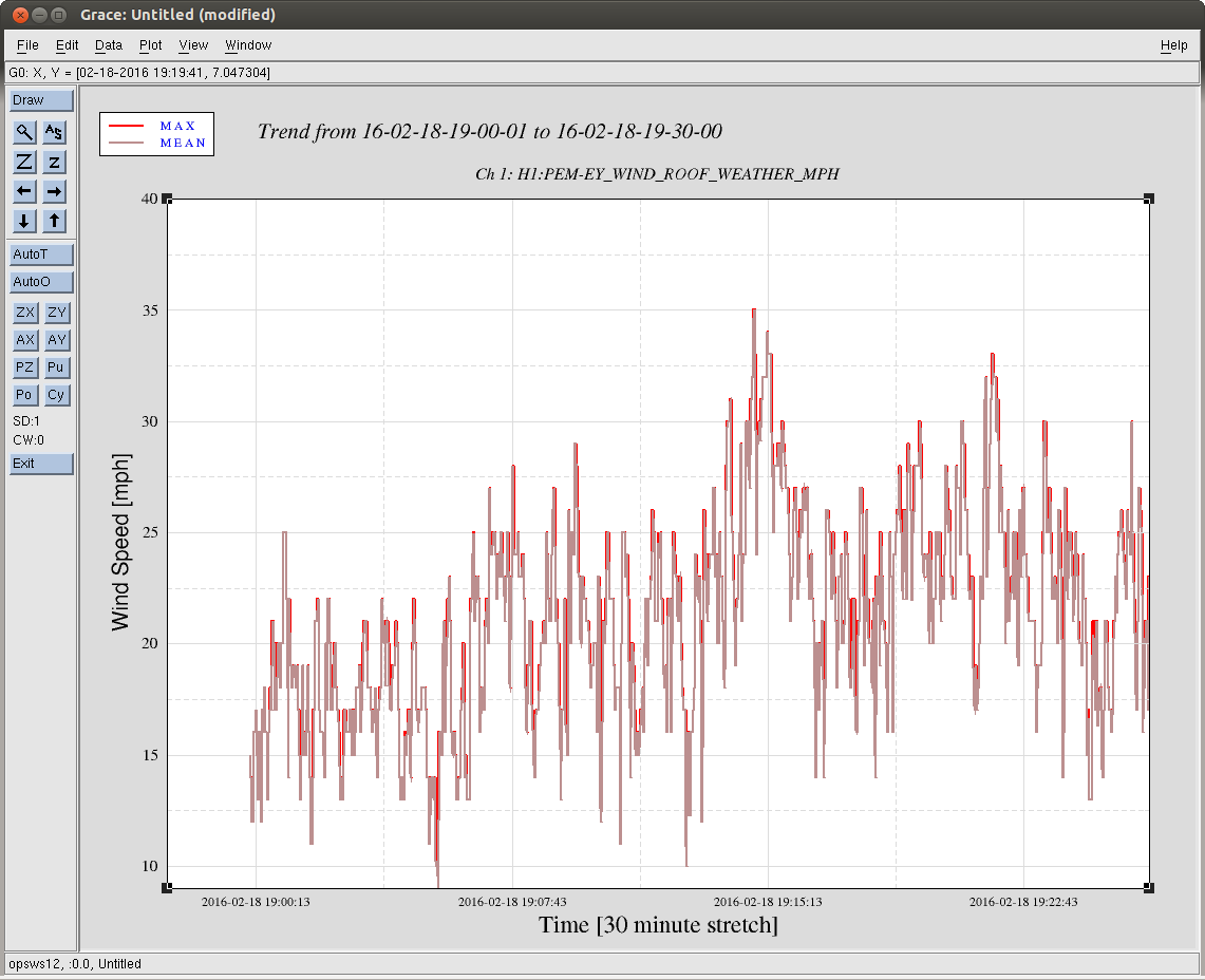
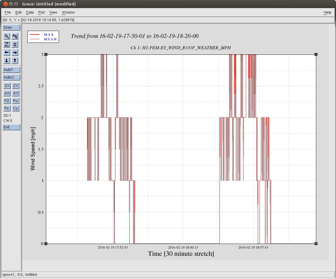
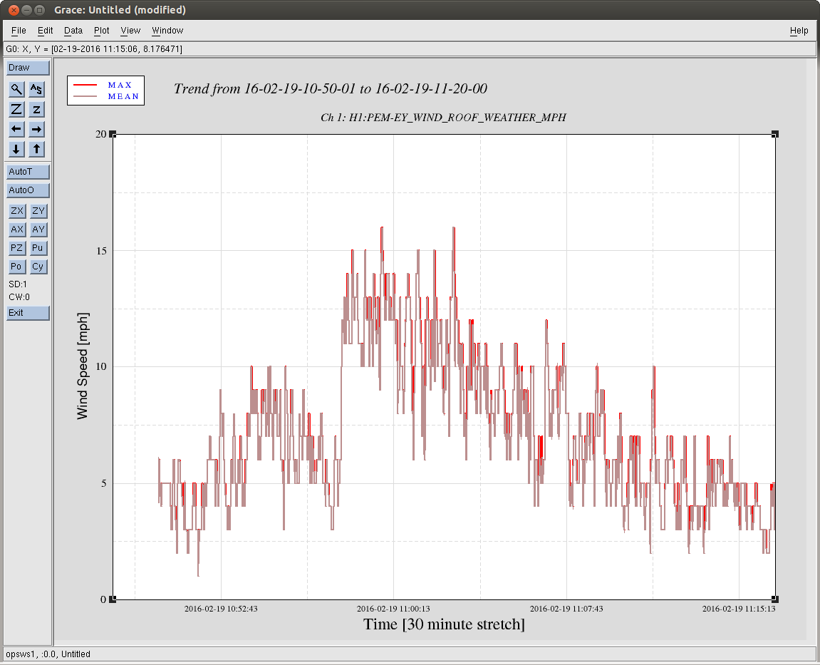
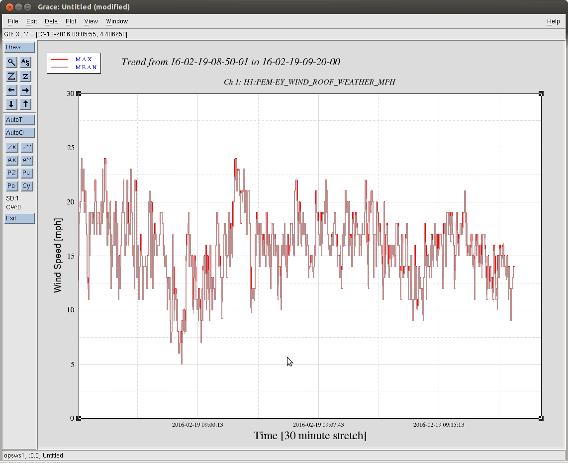
All of today's work was done in DRMI-only, since the wind was much too high to hold the arms with ALS. So, we'll have to re-visit these phasings, but hopefully they'll only be small tweaks in full lock.
We have not yet closed the loop on the new AS 90 centering loops, since we got a bit confused earlier in the day when (it turns out) there wasn't any light on the AS WFS. Keita has set gains and phases to match the current DC centering loop, so we should be able to just change the input matrix elements (same values) over to the AS 90 column.
Overall a good day, but we need to keep pushing forward.


The detailed procedrue we used to phase the REFL WFS' is summerized below:
### determining the relative phase of 4 quardrants using the length signal ###
Drive IMC_MCL_EXC with ~1000 cts at 4 Hz.
Turn on 4 Hz bandpass filters in I1-I4, Q1-Q4 filter banks
Phase s.t. the signal in each quardrant apears in I phase.
Looking at 4 I channels together to make sure no they are in phase and no sign flip.
Turn off MCL drive.
### checking the phase for alignment signals ###
Turn on resG filters in MICH, PRCL, SRCL.
Drive PR2 M3 by dithering pit or yaw, 1 at a time
Confirm I1, I2 in phase and I3, I4 opposite phase for pit; I1, I4 in phase and I2, I4 opposite phase for yaw.
Turn off PR2 drive; turn off resG in length loops; turn off bp filters in segments.
Done.
### step size for phase adjusting ###
1 deg for 9 MHz, 5 deg for 45 MHz
#########################################
Using the way above, the new phases for the REFL WFS are (in [deg])