[Cao, Ellie, Dave O, Aidan, Kiwamu, Nutsinee]
To whoever will be the last to leave control room after commisioning tonight, we would like to run a script to test whether the beam on the Hartmann wavefront sensor is the beam coming from the HR surface of ITMY, here are the steps:
1. Turn off SR3 Cage Servo ,make sure that all mirrors are in ALIGNED state and set SUS for full lock.
2. Run a script named ringheaterITMY.py by entering "python ringheaterITMY.py" on the terminal (the terminal should have been already visible on the screen with the command).
This script will change the offset values:
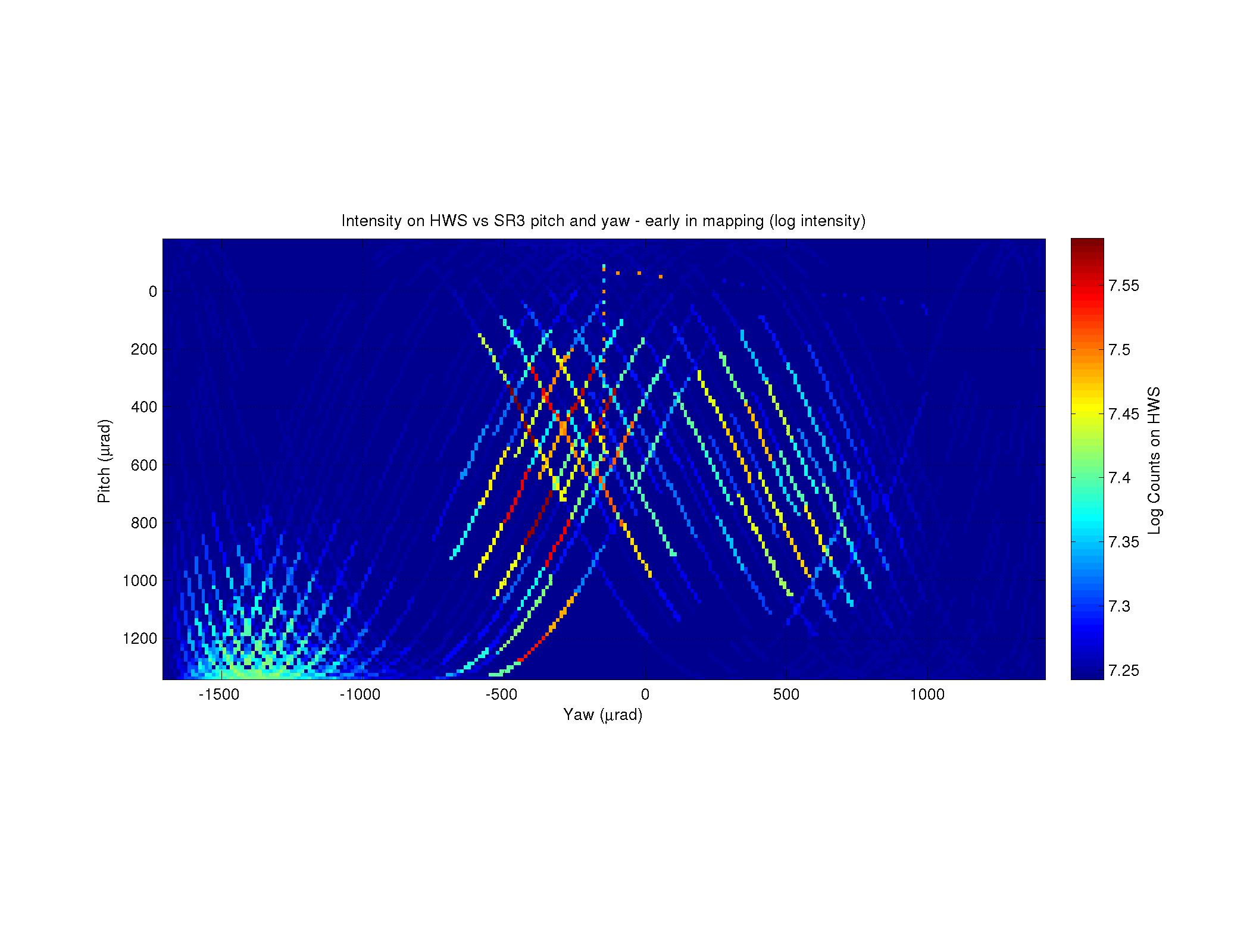
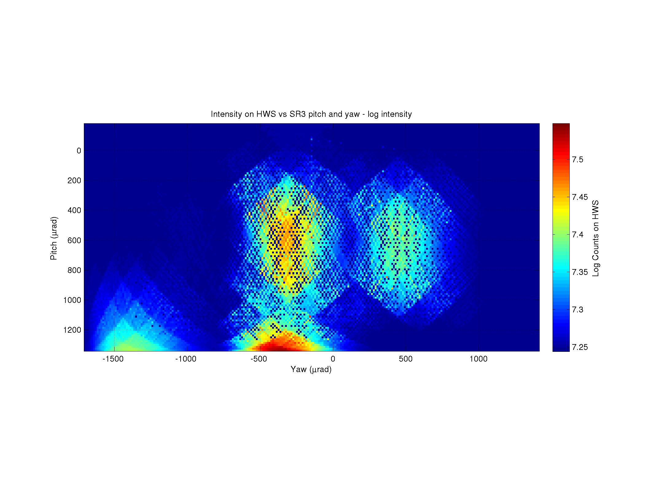
SUS-SR3_M1_OPTICALIGN_P_OFFSET from 575.0 to 1574.8
SUS-SR3_M1_OPTICALIGN_Y_OFFSET from -153.6 to -336.2
We believe the beam on HWS at this position is the beam reflected from the HR surface of ITMY.
The script then will turn on the upper and lower ring heaters of ITMY to 1 W for 30 minutes and then turn off. This is the test for confirming the origin of beam spot on HWS.
The script is saved in folder HWSYAlignment folder in Home folder.
All relevant windows should be readily visible on desktop opsws3 10.20.0.133