kyle.ryan@LIGO.ORG - posted 17:11, Sunday 14 February 2016 - last comment - 01:49, Monday 15 February 2016(25540)
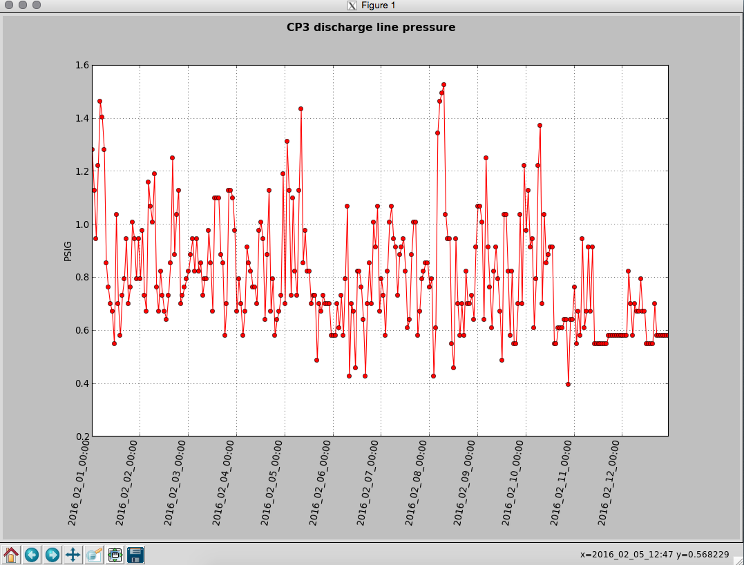
Manually over-filled CP3
1635 -1700 hrs. local -> To and from Y-mid

Behaviour a little different today.  ~5 minutes after opening the LLCV bypass valve 1/2 turn open there was no indication of vapor at the exhaust.  It took an additional 5 minutes after opening a full turn before complete.  As found, the exhaust pipe was noticeably absent most of the semi-permanent ice build up - warmer ambient temps?

Next over-fill to be Tuesday, Feb. 16th before 4:00 pm
Comments related to this report