Evan and Kiwamu,
We have been unable to lock the interferometer since this Tuesday (alog 25431). We finally identified and fixed the problem.
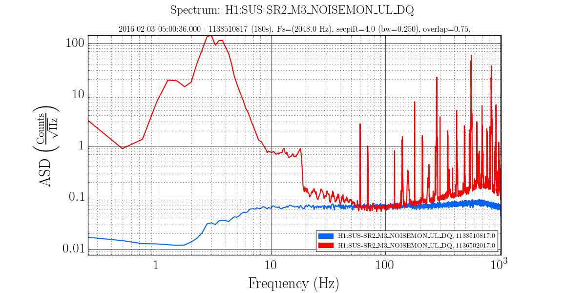
It was the cage servo of SR3 which for some reason had a too high control gain and therefore kept feeding sensing noise to the suspension up to 1 Hz. We are happy now.
[Symptoms]
The symptoms were described in Evan's original alog.
In addition, today we noticed that the lock loss in DRMI often happened with a mode hop, indicating that some kind of misalignment was involved. Since the mode hop can be easily triggered by the large optics (i.e. BS, ITMs, PR3 and SR3), we suspected the large optics. Then, we found that we could stably lock PRMI which pointed us to SR3.
[Something happened in this Tuesday]
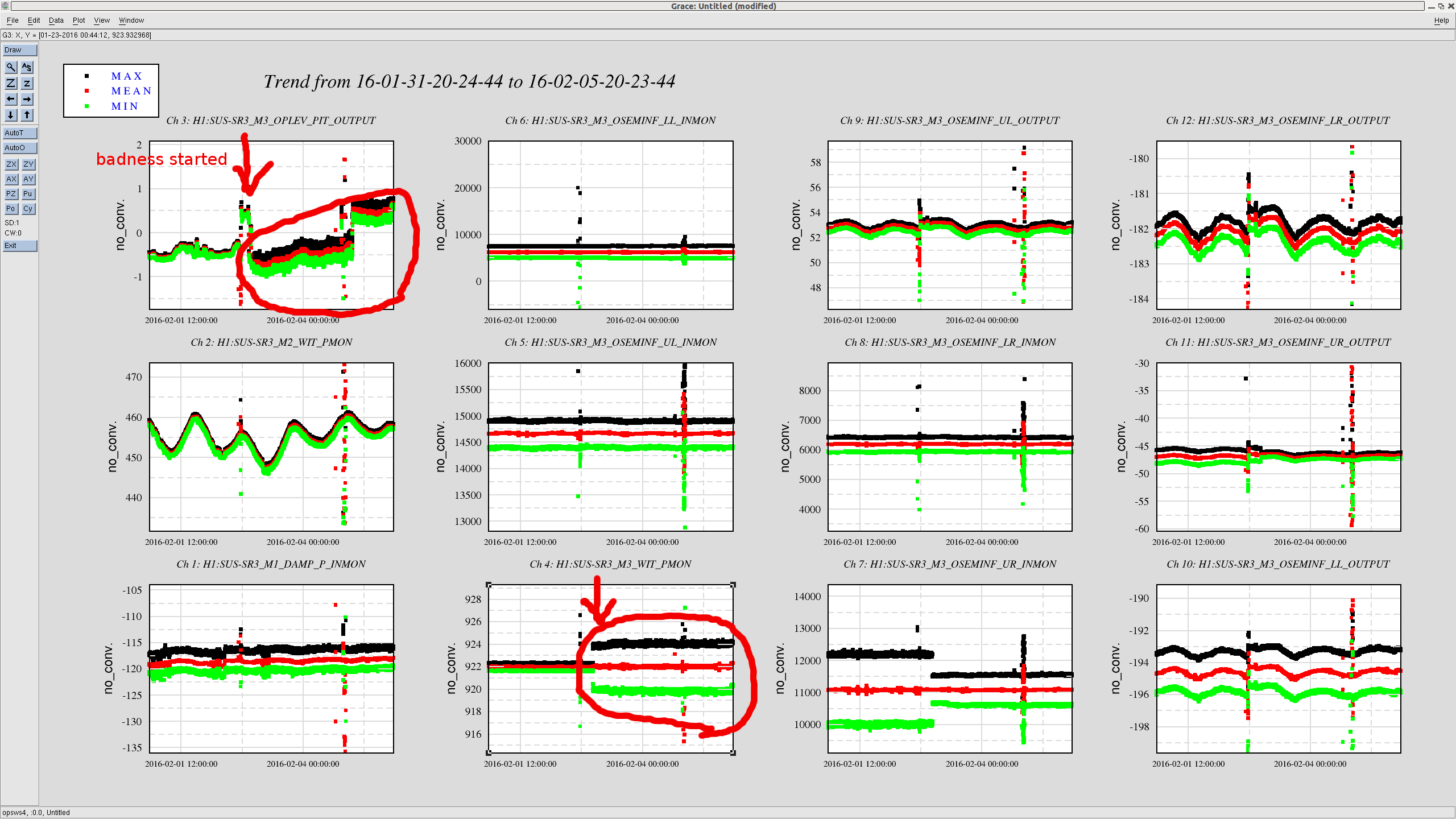
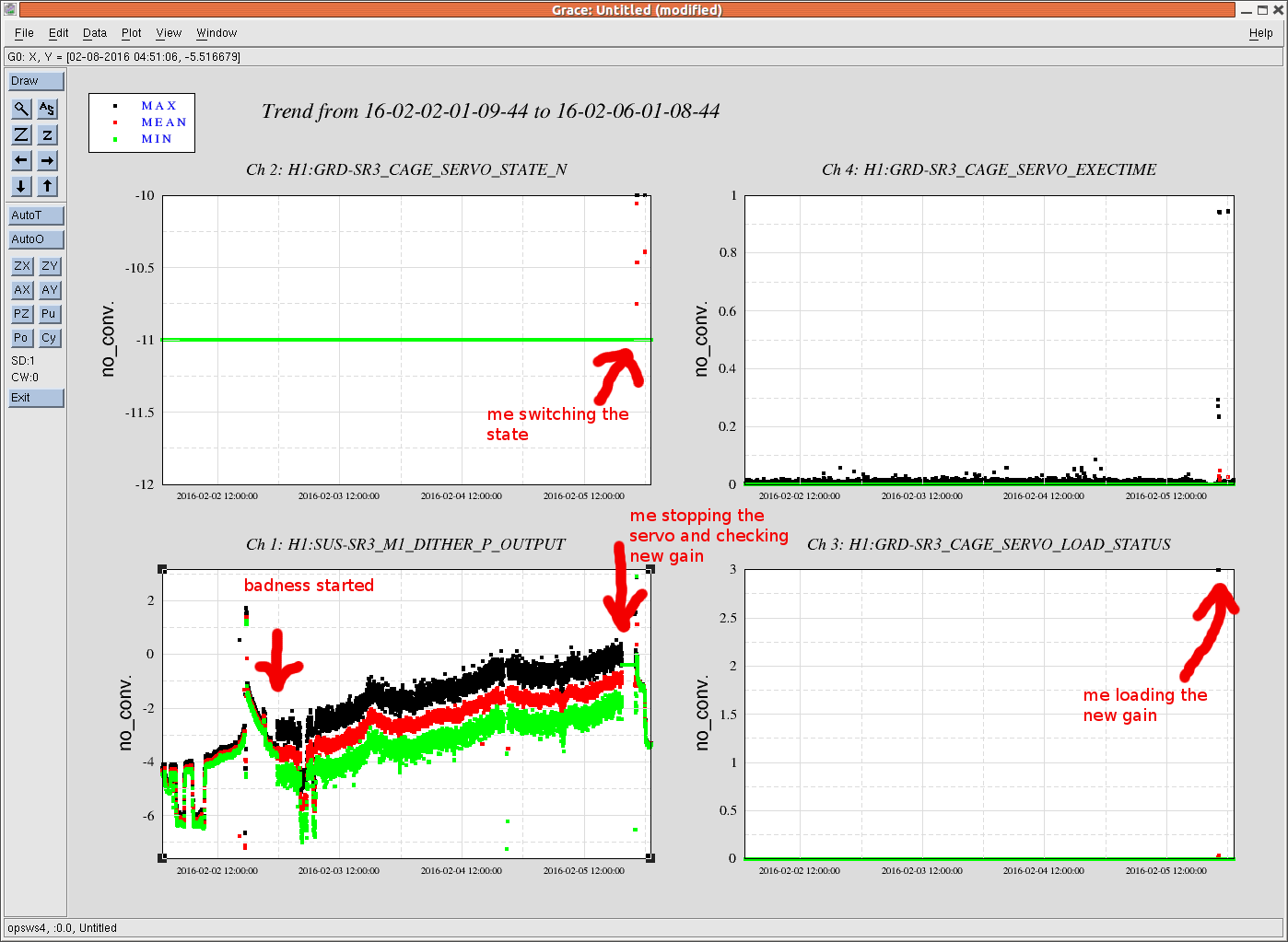
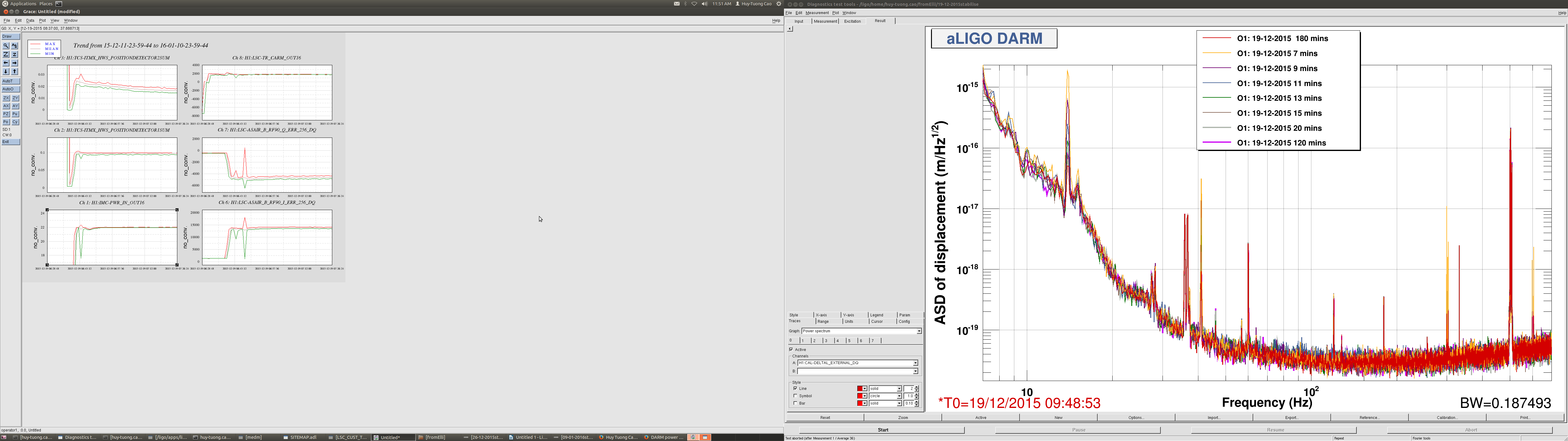
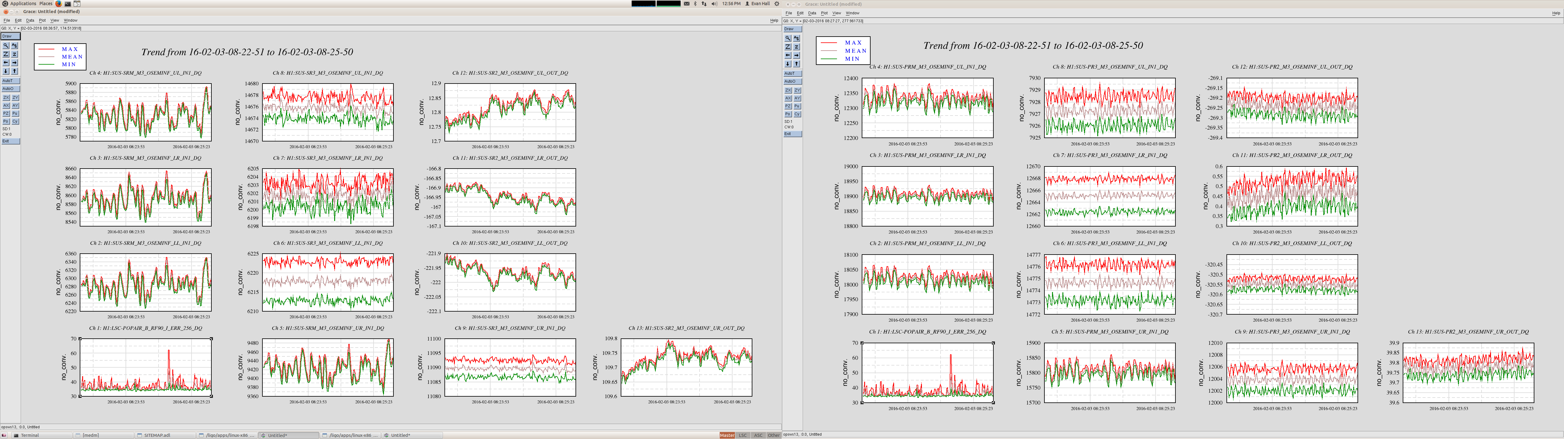
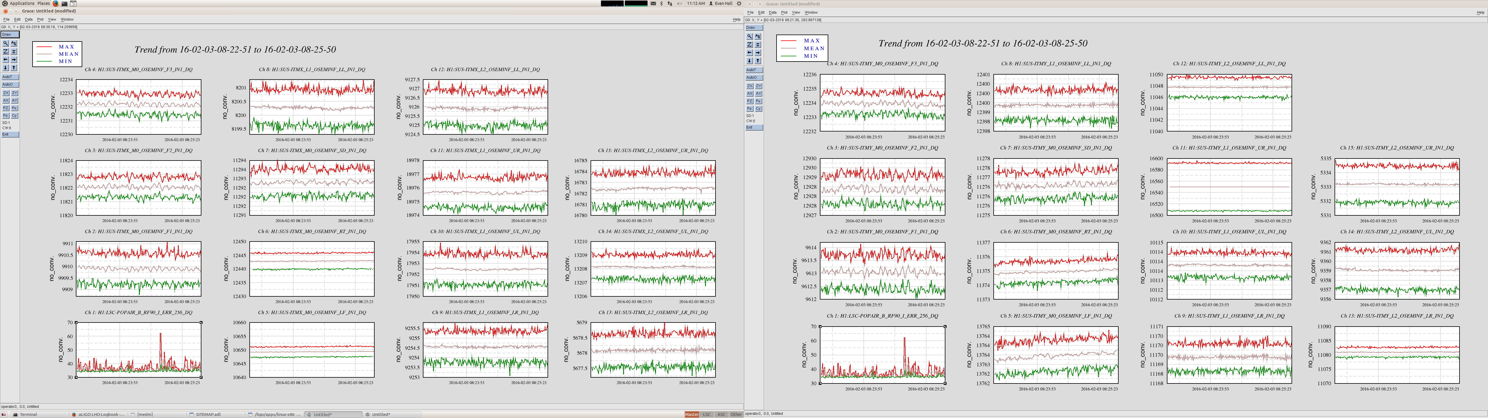
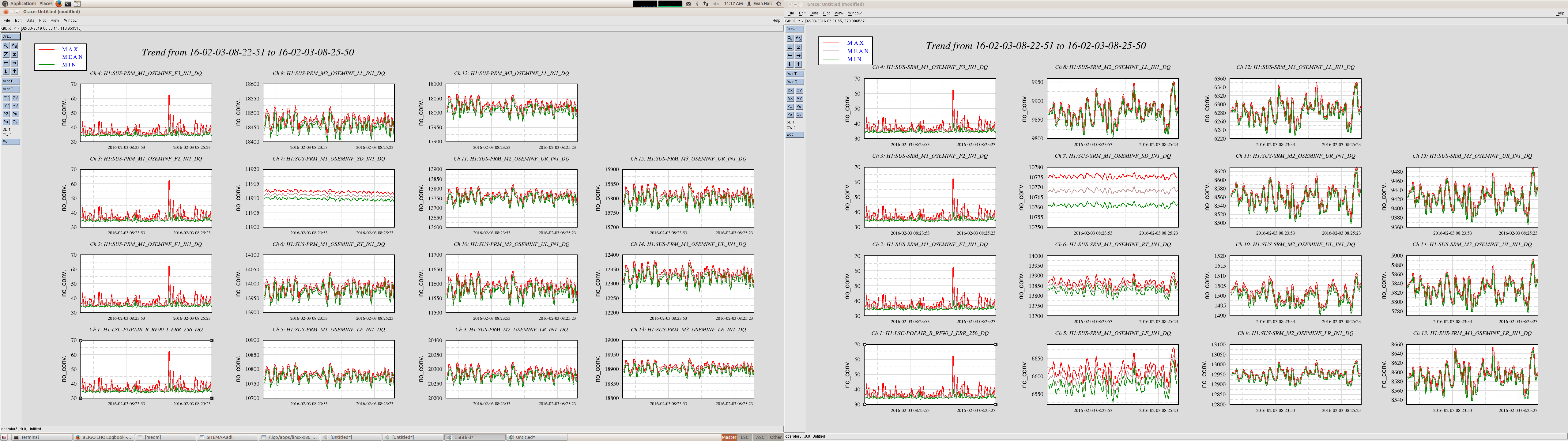
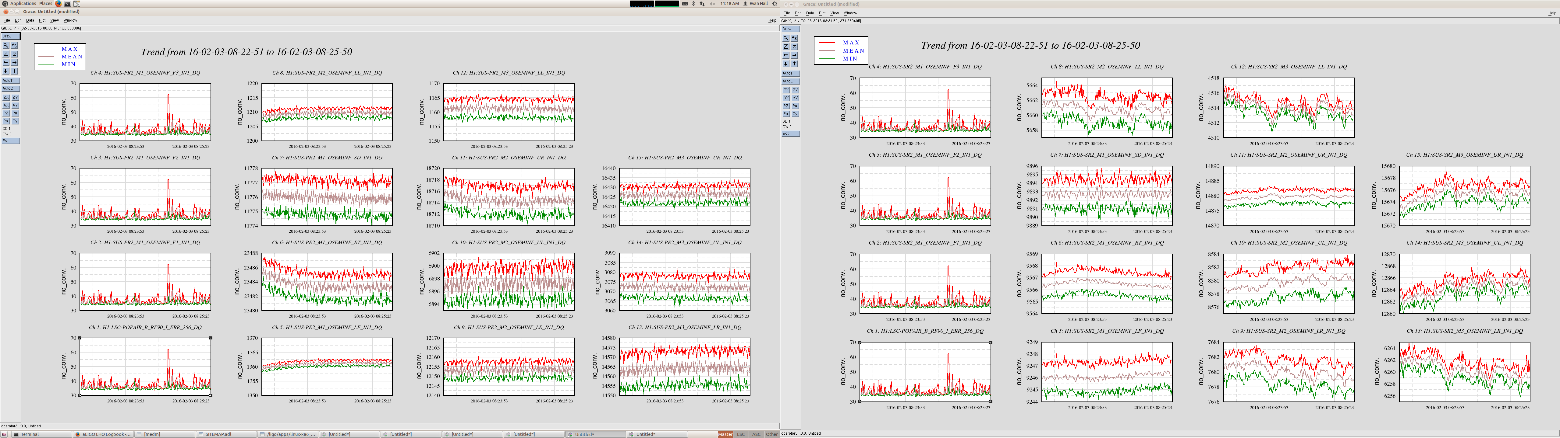
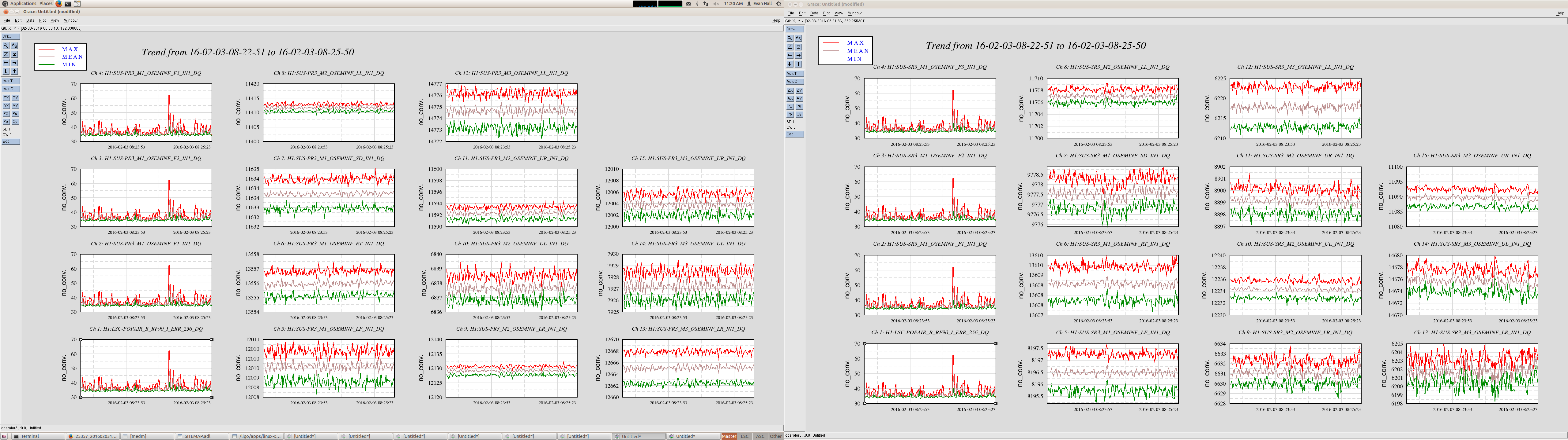
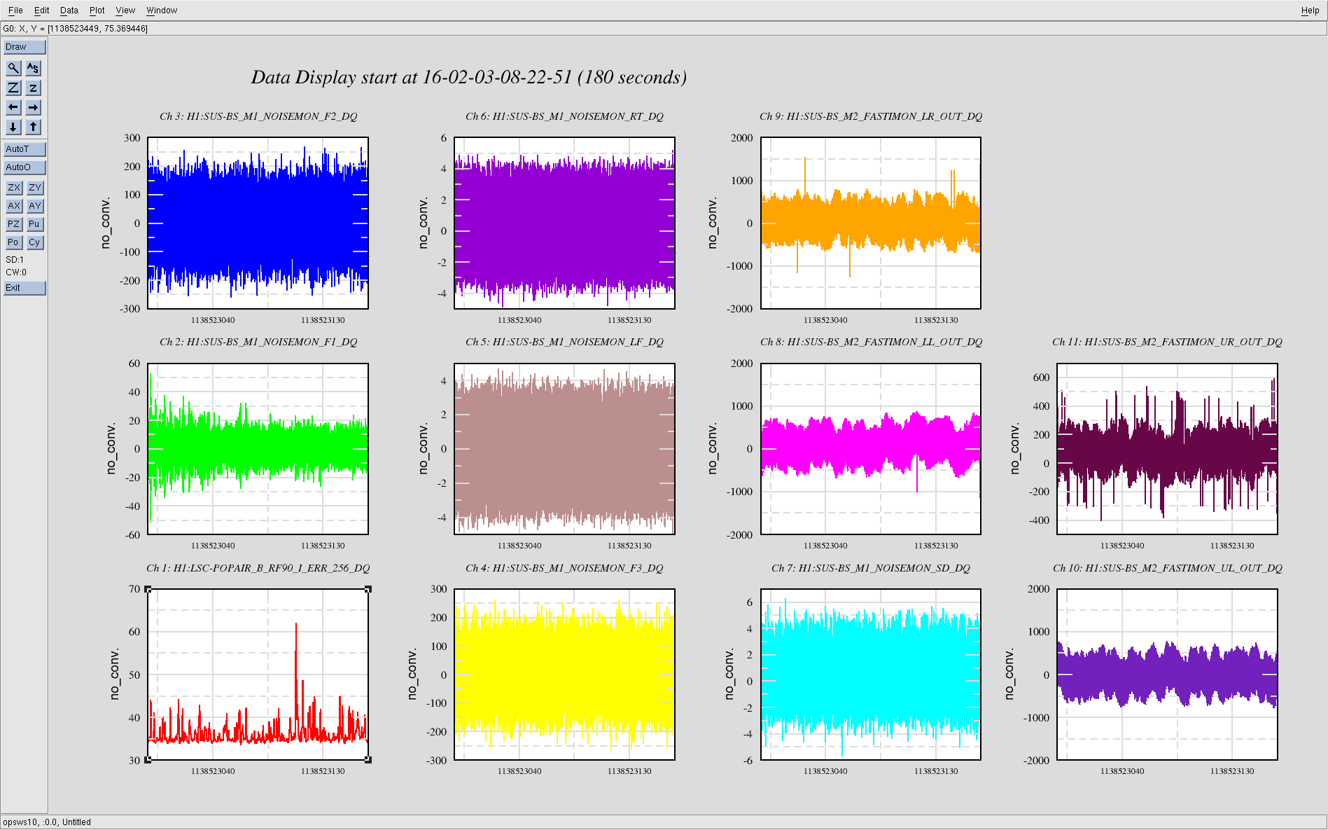
Trend data showed increase in the pitch motion of SR3. See the attached. The increase of noises occurred at around 4 pm local time of this Tuesday. We have no idea what triggered this situation.
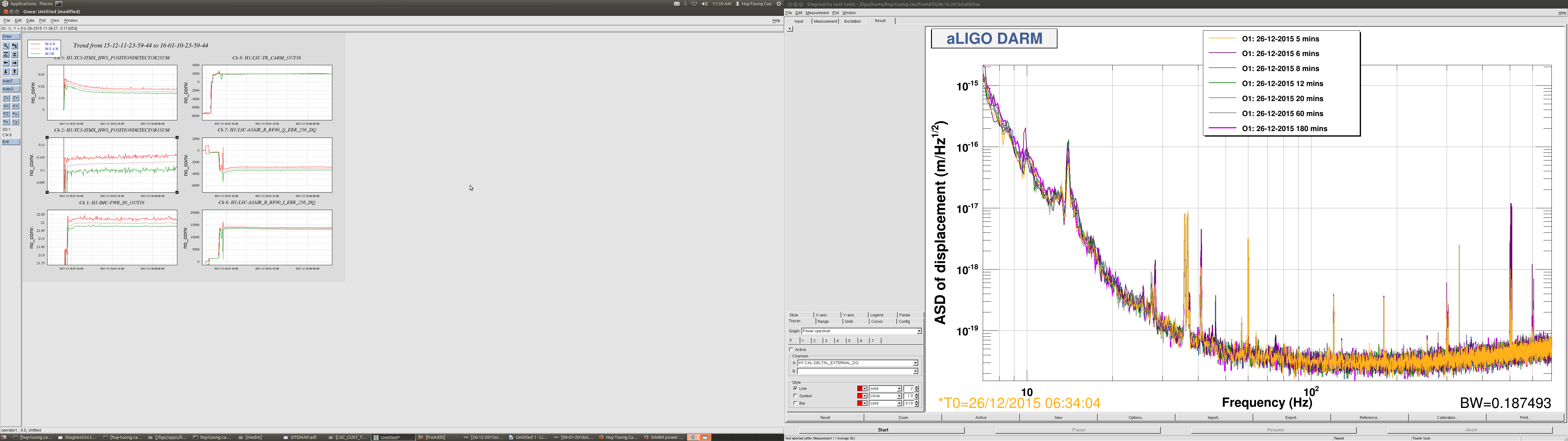
By the way, the UR OSEM seemed as if it had reduced noise, but it turned out that this was due to the 60 Hz power line for some reason decreased at the same time. We then switched off the cage servo to see if it improves the situation. Indeed it did. In fact DRMI was able to lock more stably.
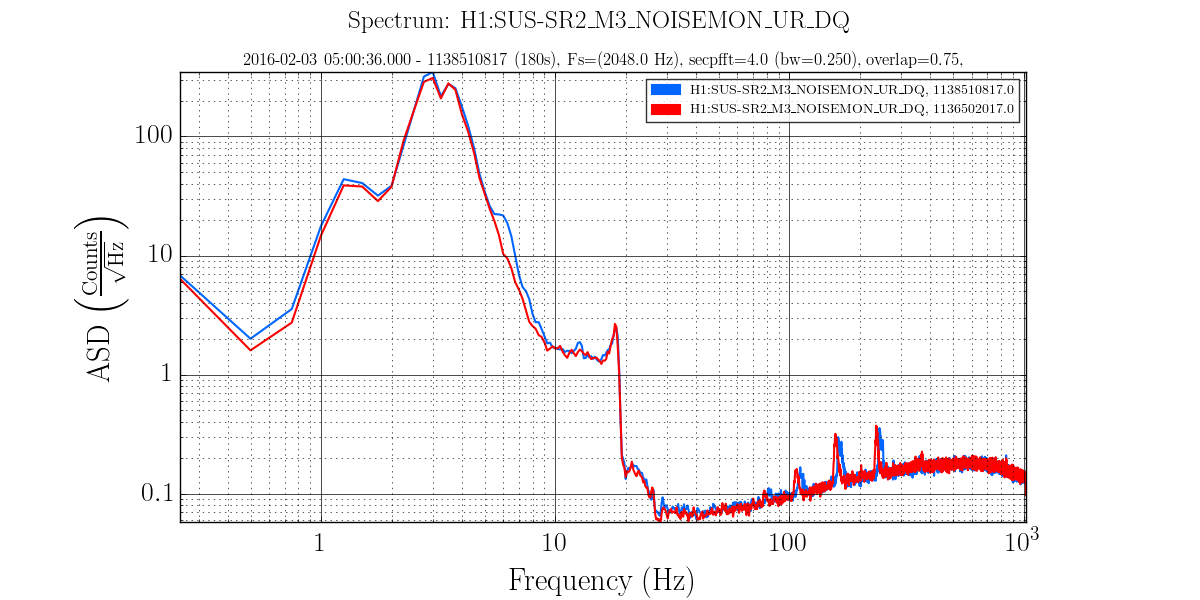
We have checked the damped spectra of the top and bottom stages without the cage servo comparing against the past ones (alog 17781). We did not find any obvious issues with the suspension when the cage servo was off. At this point, we concluded that the problem is in the cage servo code rather than the suspension or its damping system.
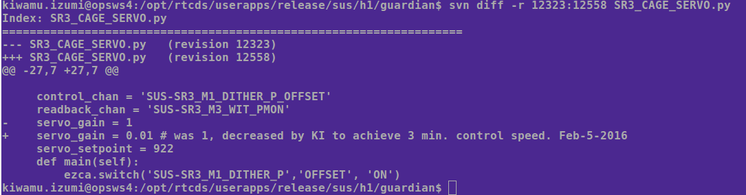
[The fix]
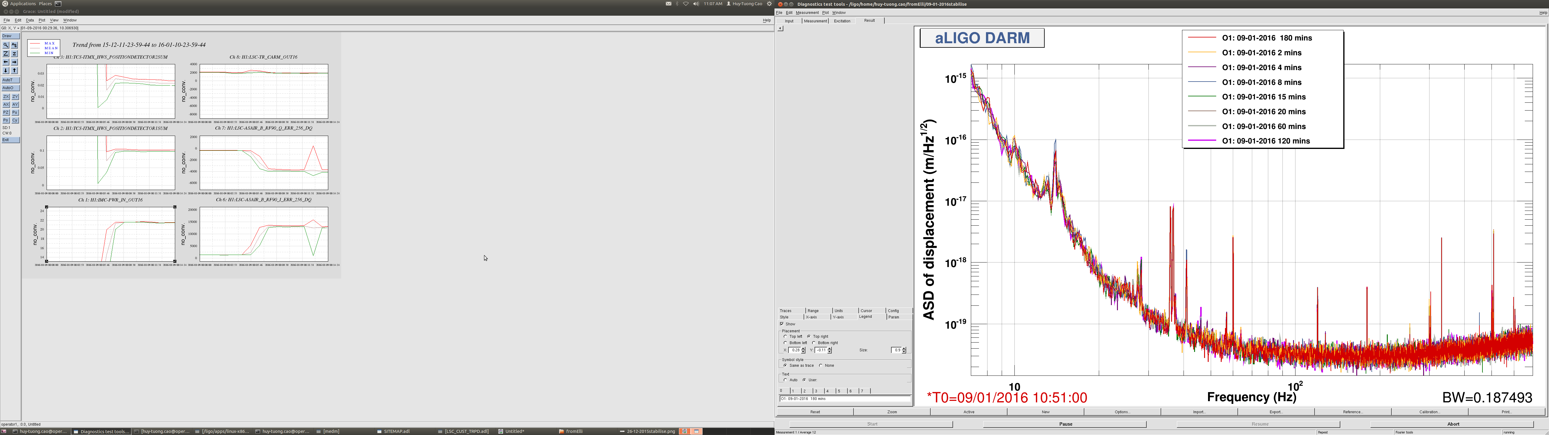
We lowered the control gain in the guardian by a factor of 100 which may sound big to some readers, but this gave us a good control time scale of 3 minutes according to a coarse impulse response test.
The resulting spectra at the top and bottom stages seemed as quiet before. So this is good. The code is checked into SVN.
We still don't understand why this happened.