TITLE: Dec 21 EVE Shift 00:00-08:00UTC (16:00-00:00 PDT), all times posted in UTC
STATE Of H1: Observing @ 80Mpc
SUPPORT: N/A
INCOMING OPERATOR: Jeff B
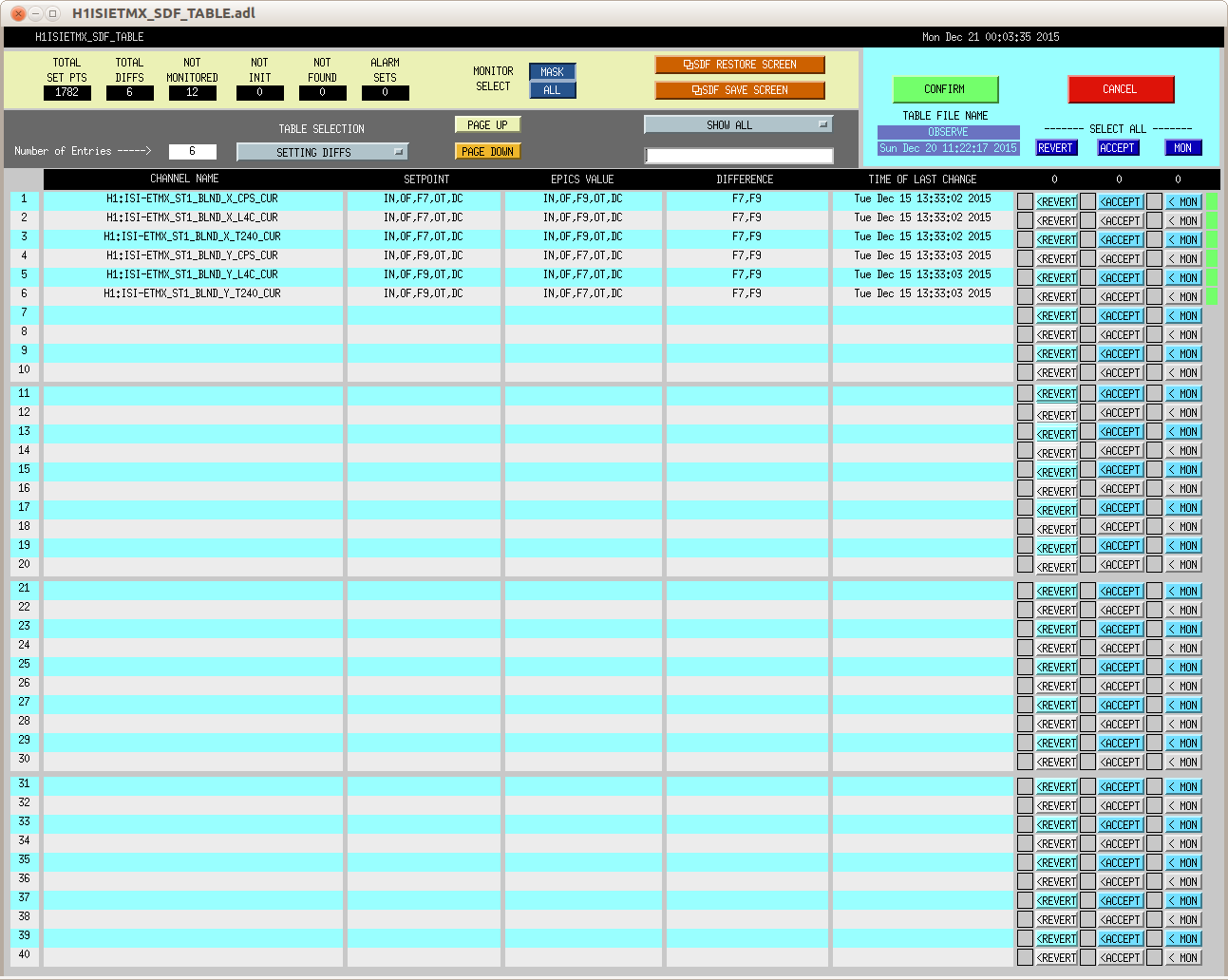
SHIFT SUMMARY: Lots of trouble with µSei and a bit of wind that blew up. The details are in the activity log. ISI Blends set to 45Mhz around the board except for ETMX off axis
ACTIVITY LOG:
01:15 Trouble with input align. PR2 pointing was bad. Yaw was off by 6µrads
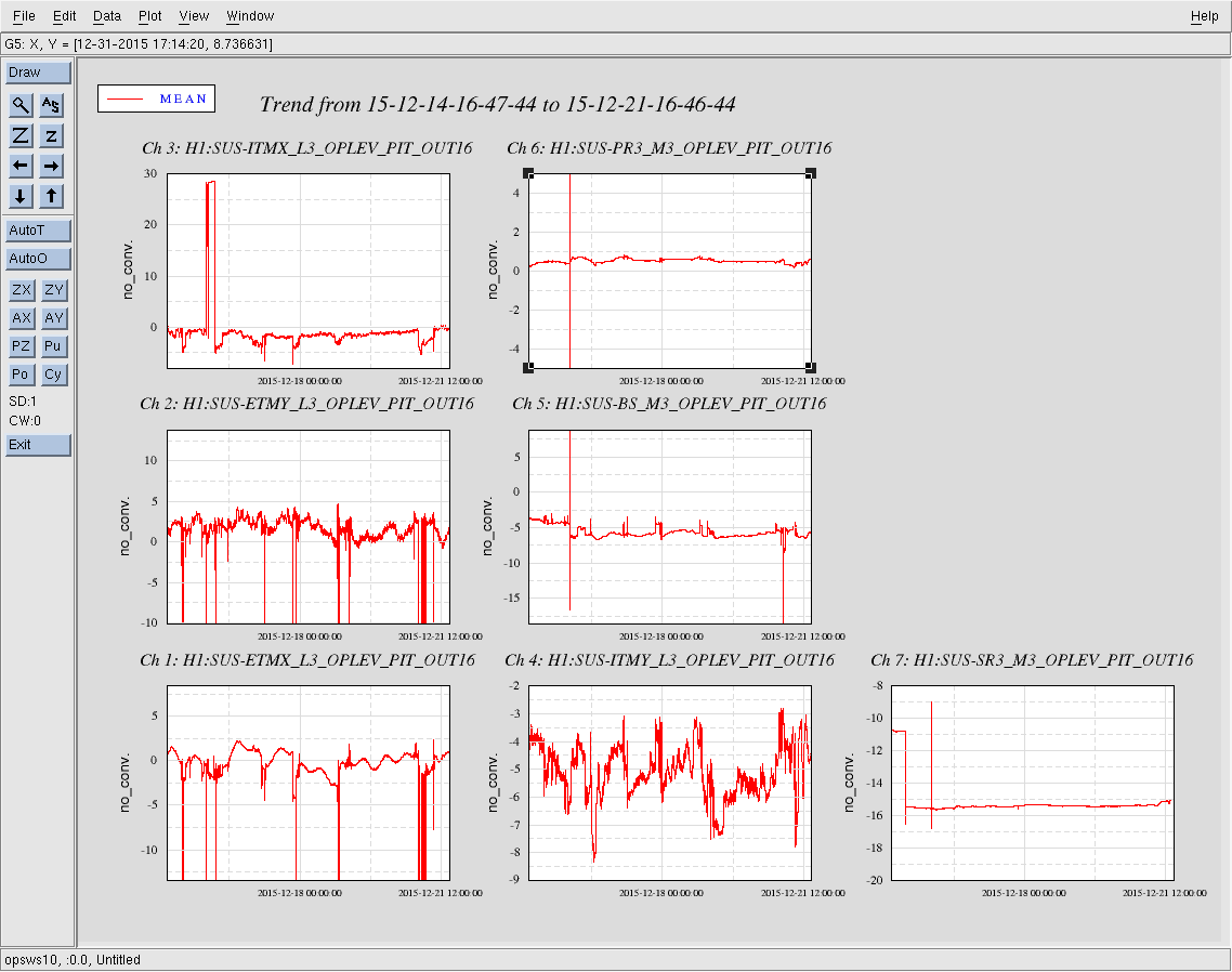
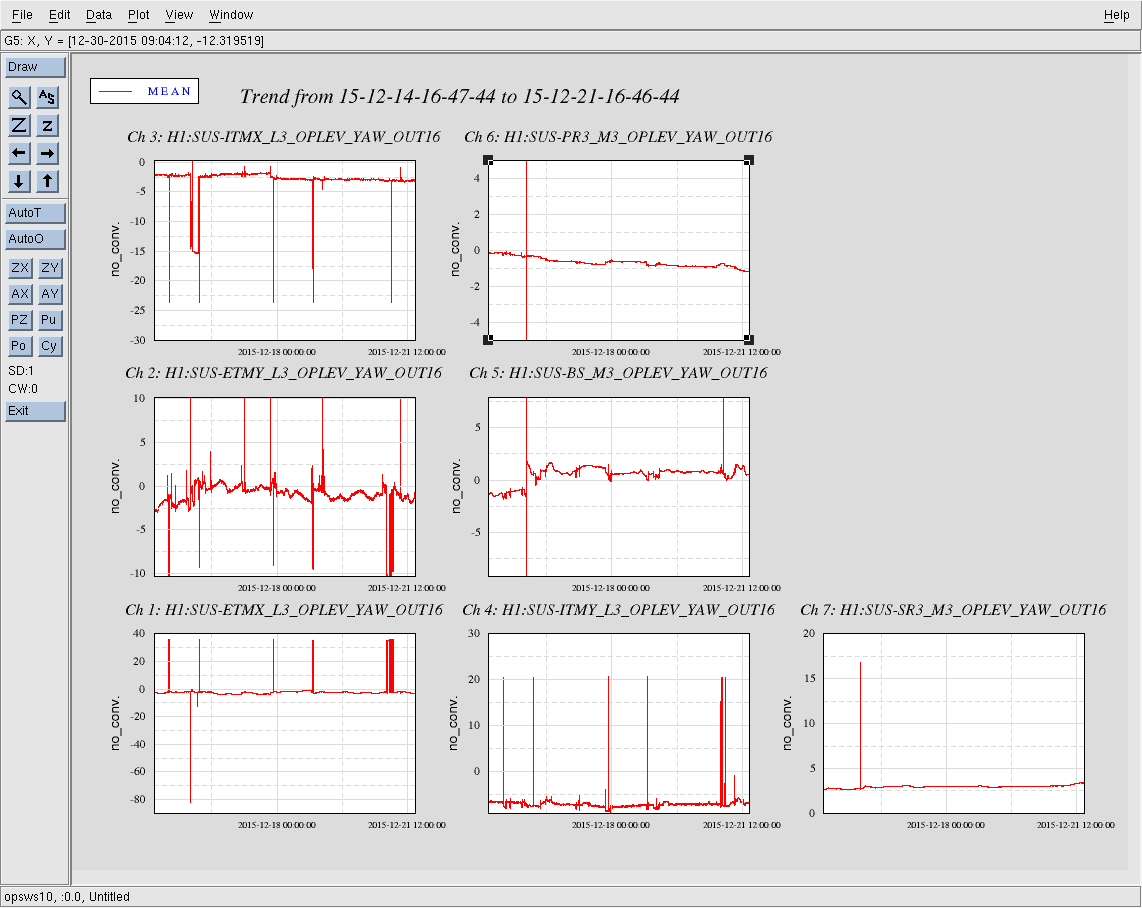
01:18 Dark mitch still won’t grab. µSei is now peaking around 1.5µm/s. Wind is still NOT an issue. The beam splitter appears to be really feeling the ground motion.
02:50 Touched base with Jenne just to apprise her of the IFO situation
03:00 took ISC_LOCK to down. There doesn’t seem to be any locking (ie Dark Mich, PRMI or DRMI) going on in my near future. uSeism is still trending above 1um/s and the BS is jumping all over itself. th wind has also blown up to >= 20mph at EY.
05:58 PRMI locked! (first small victory)
06:01 DRMI Split mode. no time to tweak.
06:08 DRMI Split mode. no time to tweak.
06:14 DRMI Split mode. no time to tweak.
06:24 Lockloss. IMC broke lock.
06:57 DRMI LOCKED!!!!
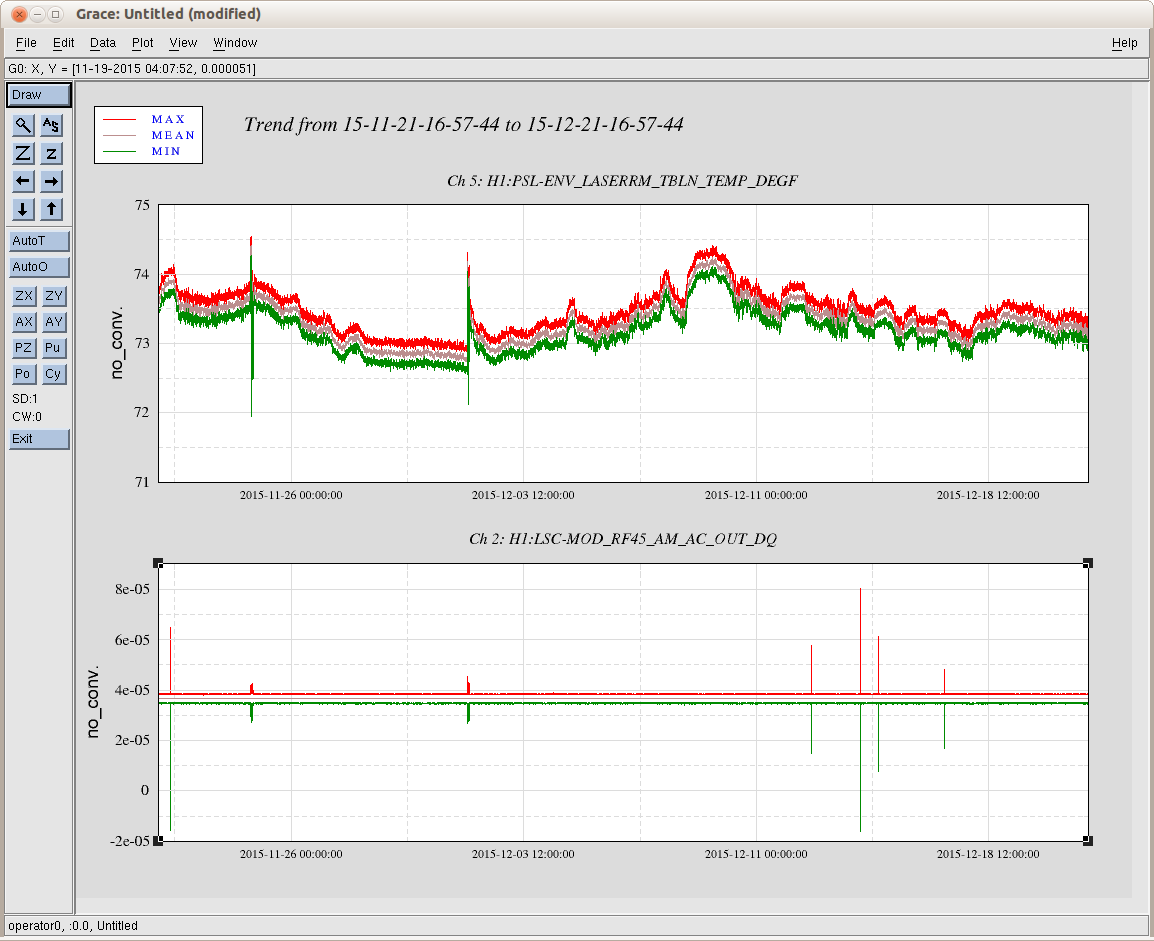
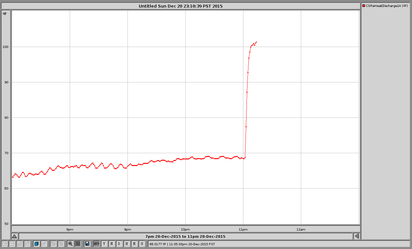
07:05 John called to tell me that he was turning on some heat in the LVEA. (H1CA)
07:13 Lost lock at COIL_DRIVERS. grrrrr
08:02 NLN!
08:04 intent it set to Observing

Site activities: Bubba driving