[Jenne, JeffK, EvanH, Travis]
On our very first lock attempt (that made it past DRMI) after today's maintenence, we lost lock during the BS coil driver switching state. Thanks to today's data saving work (see alog 25329), we now have some data to look at!
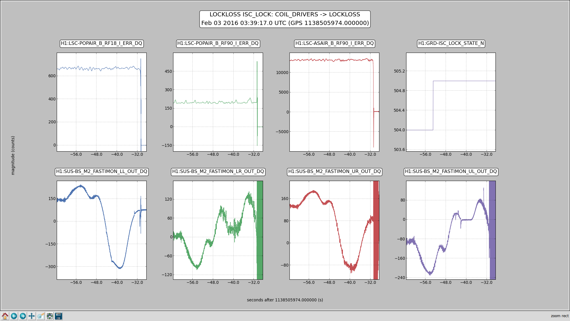
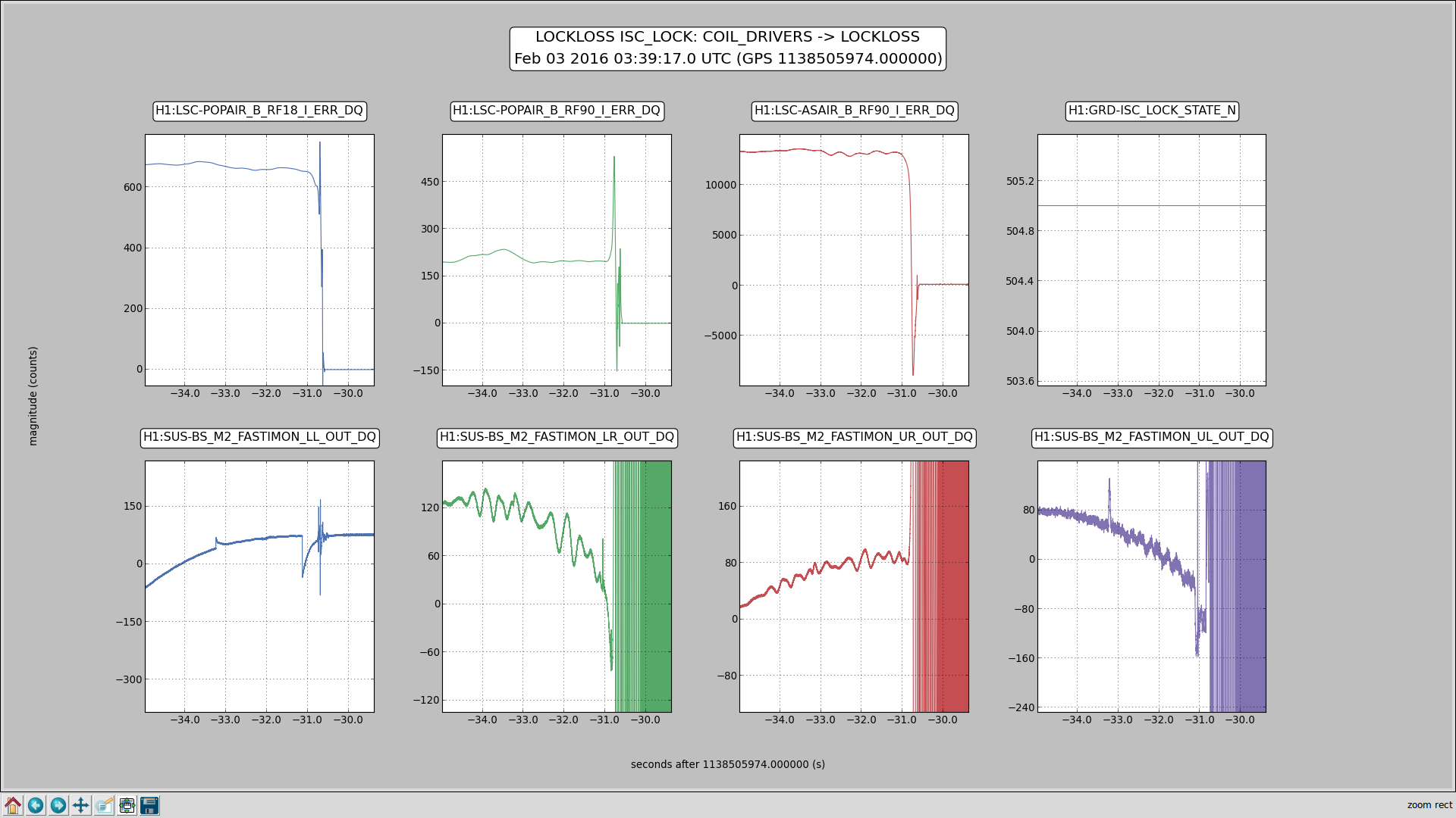
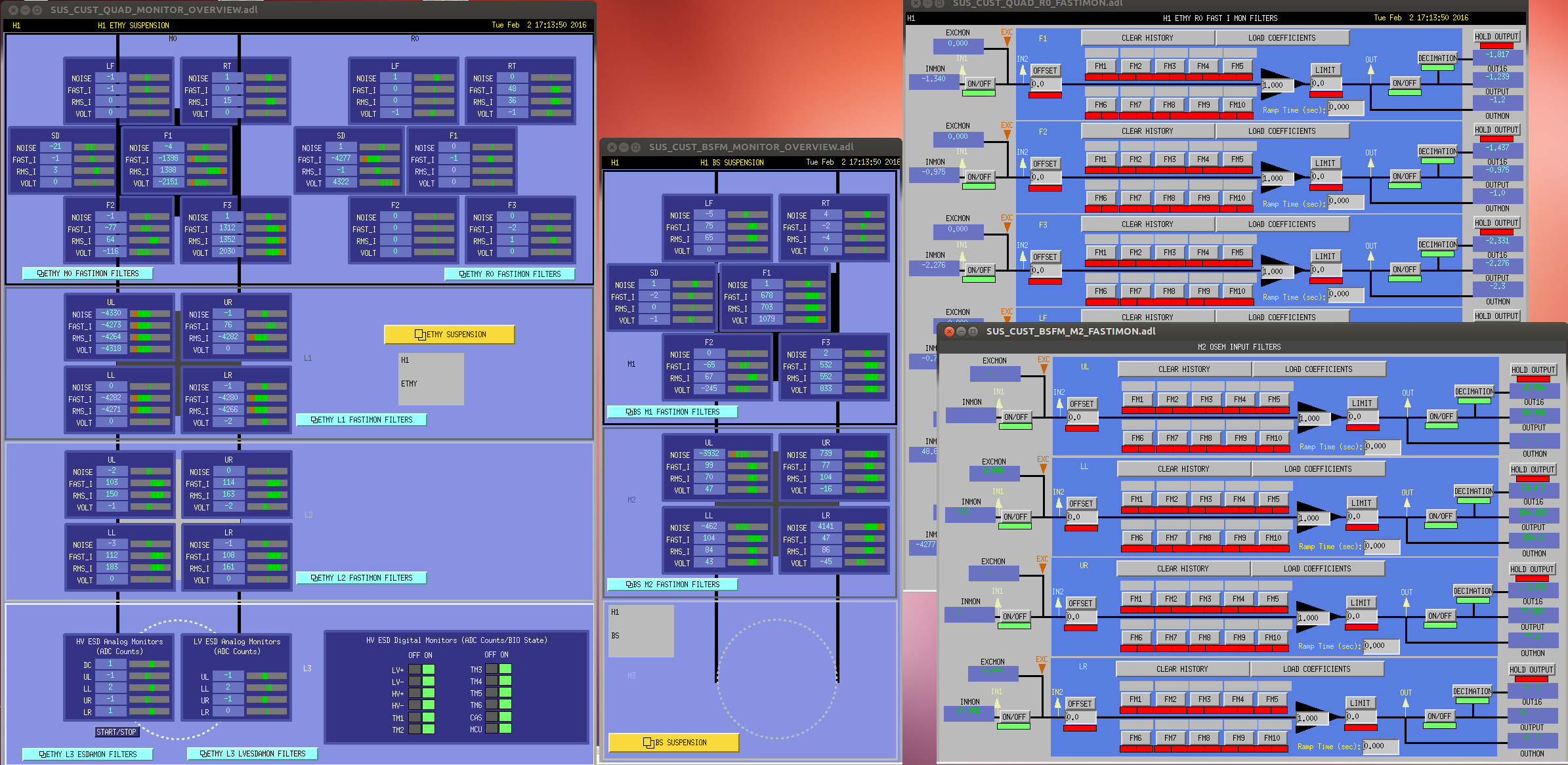
Attached are 2 figures of the same lockloss, one of which shows the whole time we were in the COIL_DRIVERS state, and the other zoomed in on the lockloss itself. On the top row of these figures, the left 3 plots are just power buildups, to indicate when the lock was actually lost. The right-most plot is the ISC guardian state - state 505 is COIL_DRIVERS. The bottom row of plots are the new FASTIMONs for each OSEM of the BS M2 stage.
These channels are plotted in units of ADC counts, but we have 40V/2^16 counts over a 40 ohm resistance, and the BS M2 actuation strength is about 1N/A. The features in the LL channel are of order 100 counts, which corresponds to about 15 microNewtons. For longitudinal, this is of order 60 nm of a kick to the BS. The rms for MICH control above 10Hz is only 1e-14 m, so this is 6 orders of magnitude above the rms. For pitch and yaw, this corresponds to about a 2 urad kick to the BS. (Newtons to meters or radians from T1200404).
This seems like plenty to explain our locklosses. Next up: what to do about it?