Sheila, Betsy, Tyler, Oli, Jennie, Camilla,
Day 1: 84193, Day 2: 84228, Day 3: 84230 and 84239, Day 4: 84274, Day 5: 84292, Day 6: 84314, Day 7: 84334
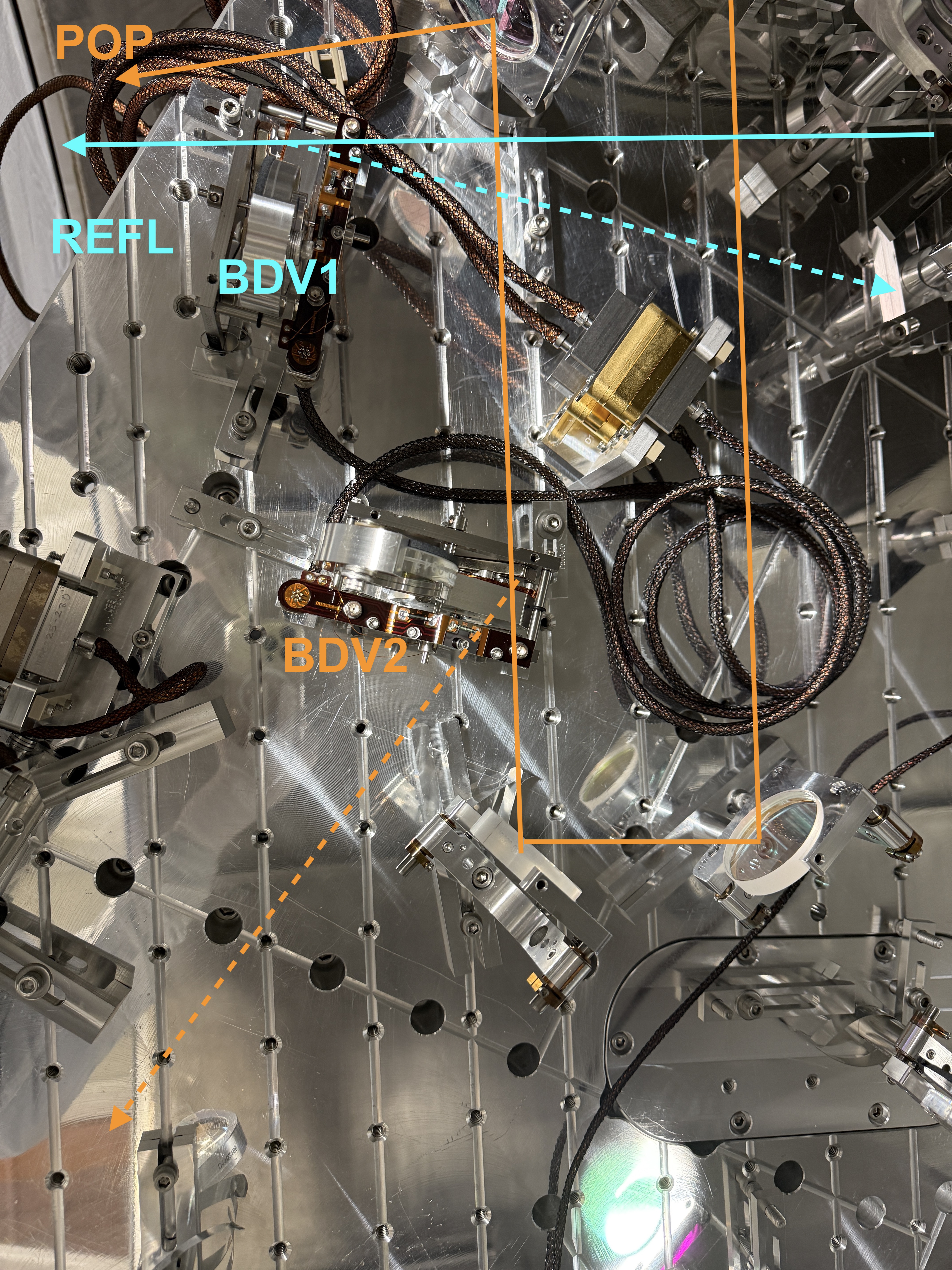
| Photos attached of: | REFL (BDV1) | POP (BDV2) |
| Location | photo | |
| Open Position | photo | photo |
| Closed Position | photo | photo |
| Beamdump Location | photo | photo |
| Beamdump Name | BD5 | BD4 |
| Beam dumped | photo | photo |
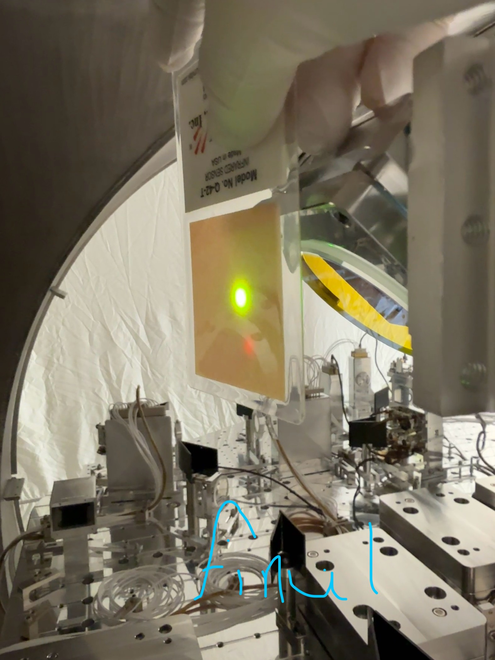
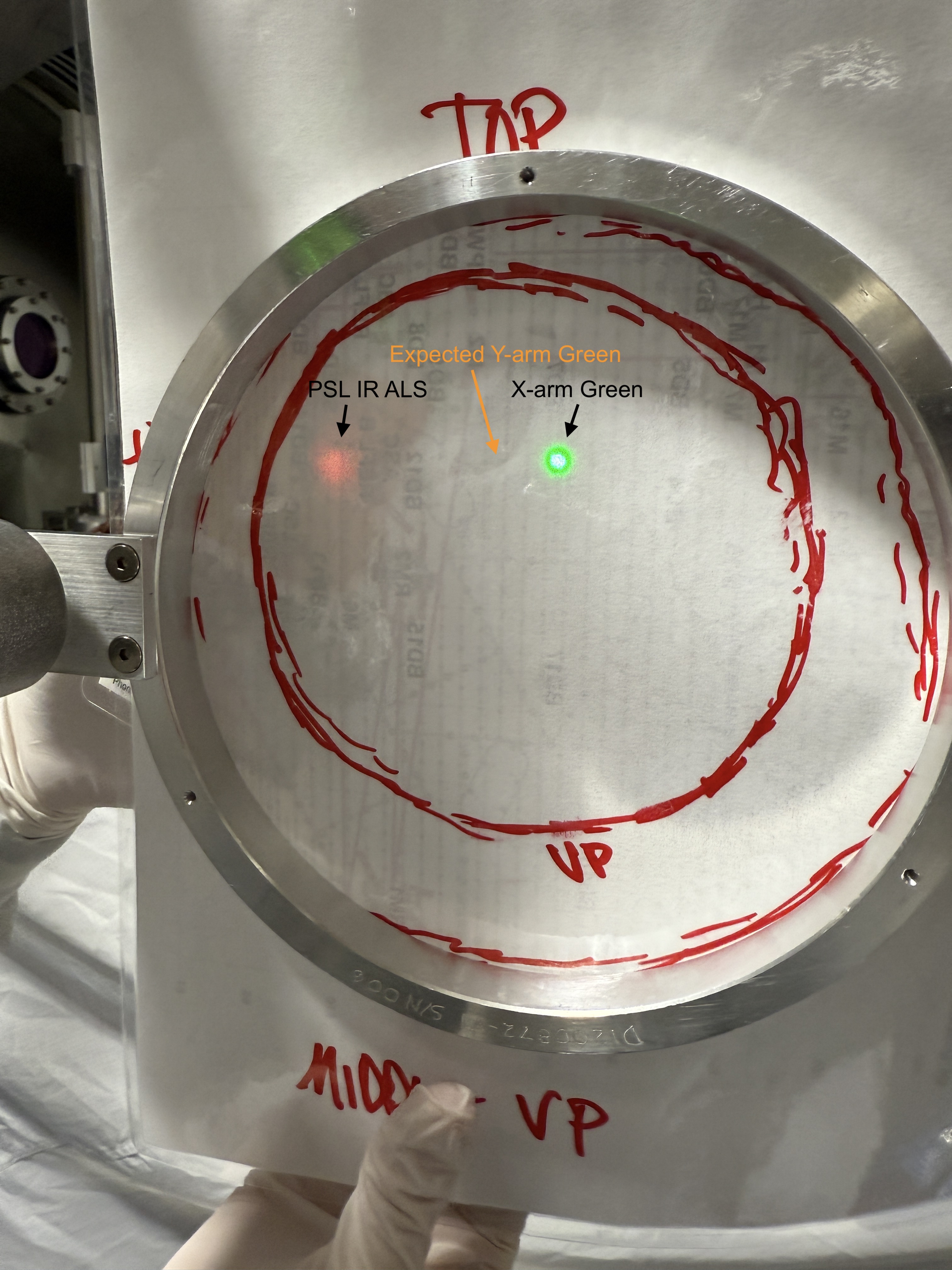
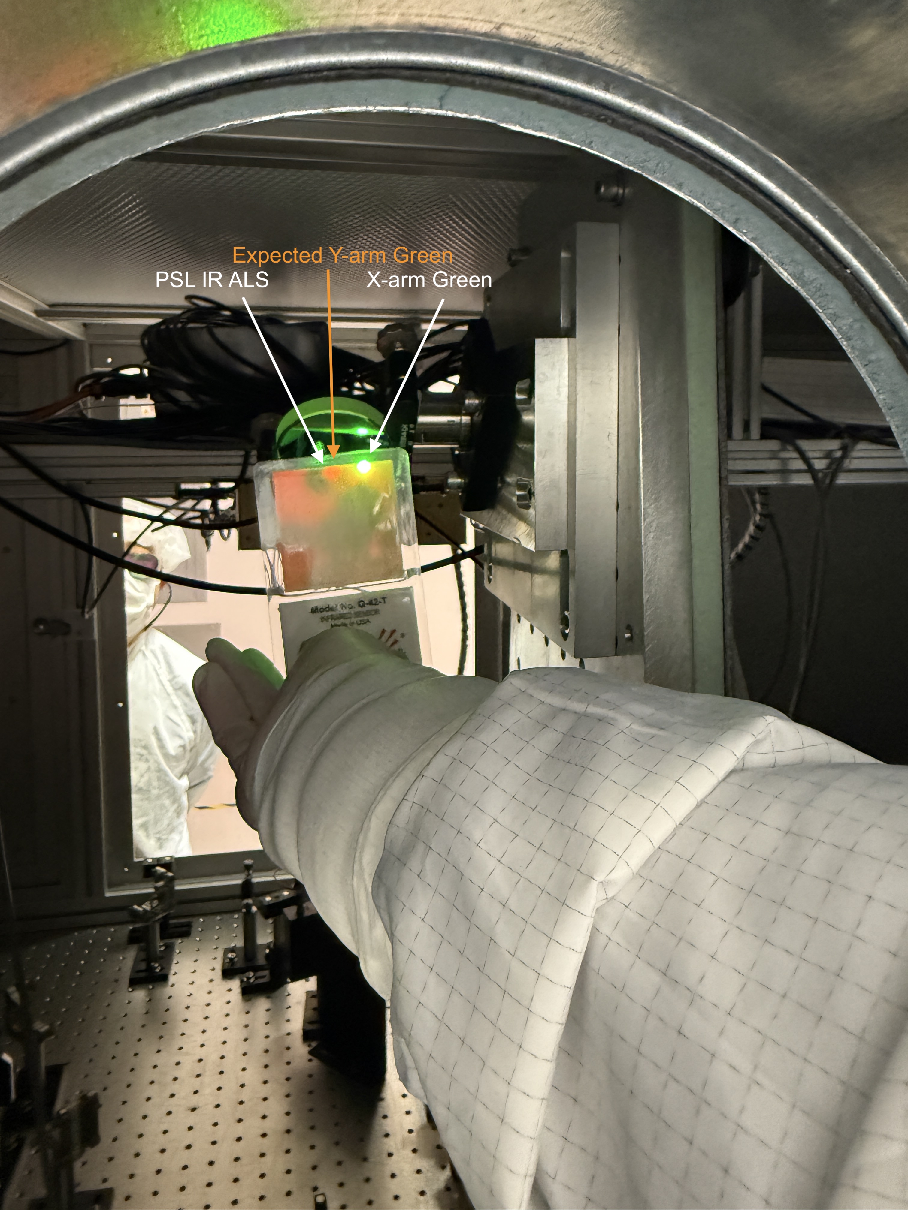
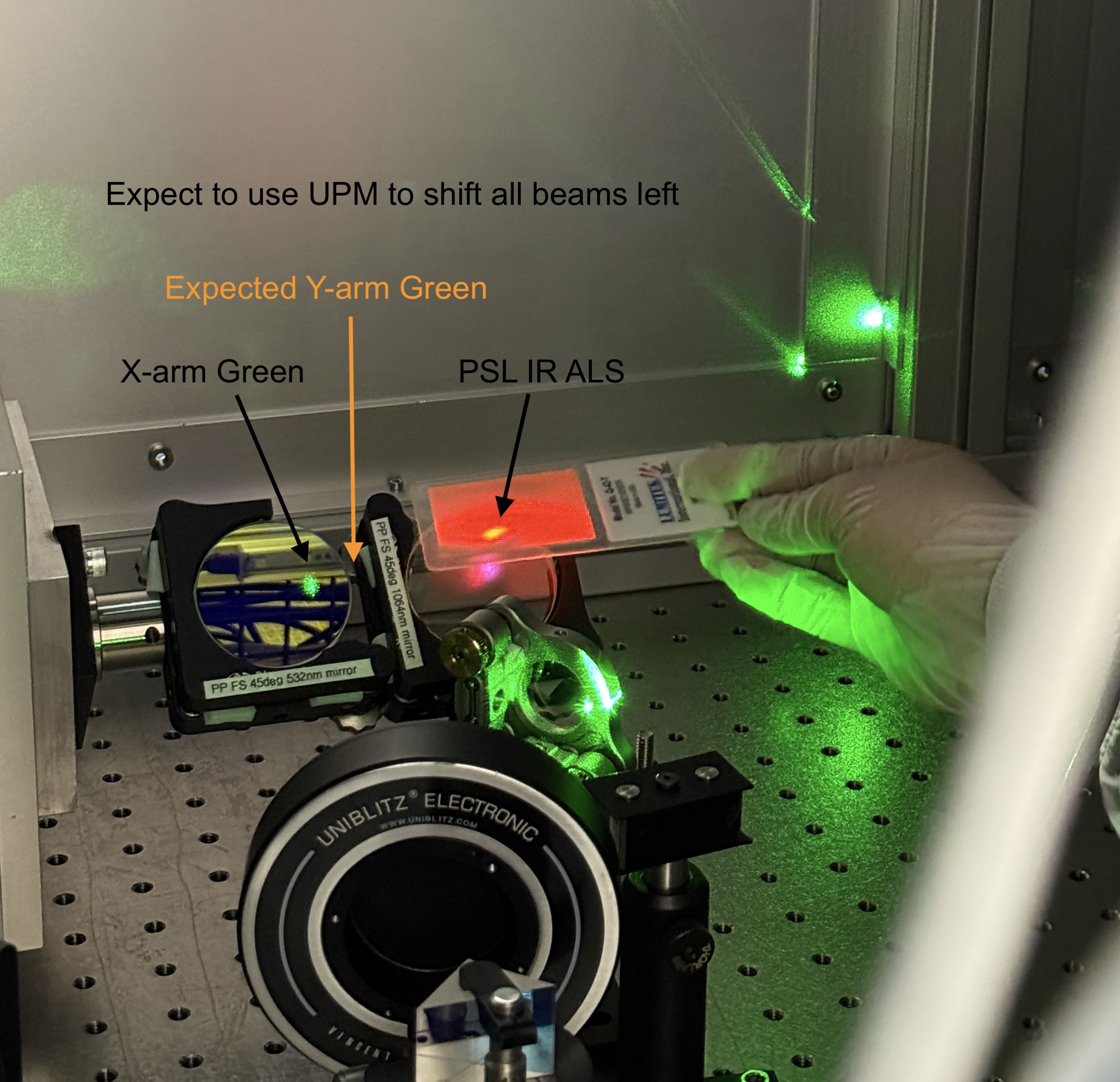
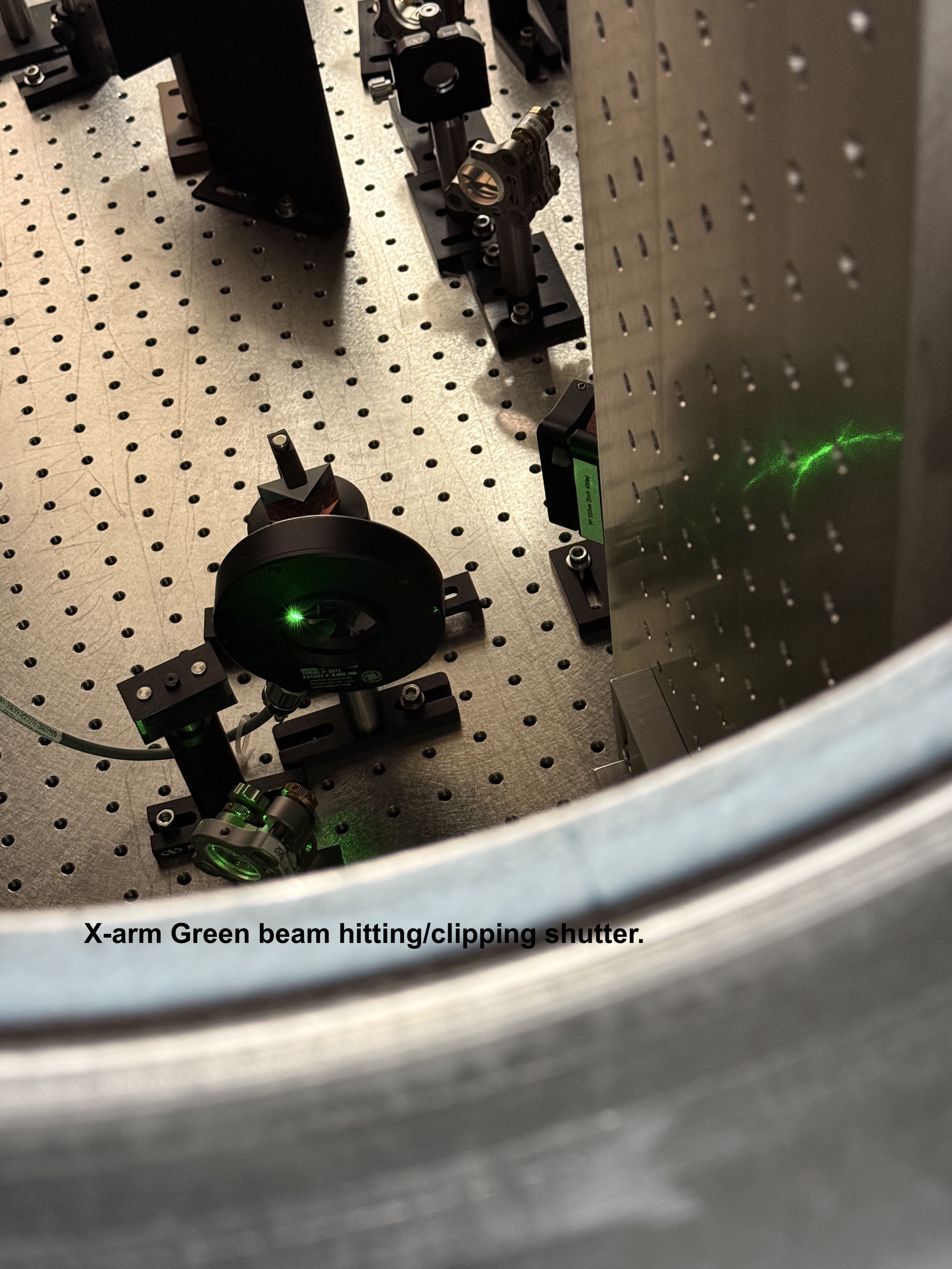
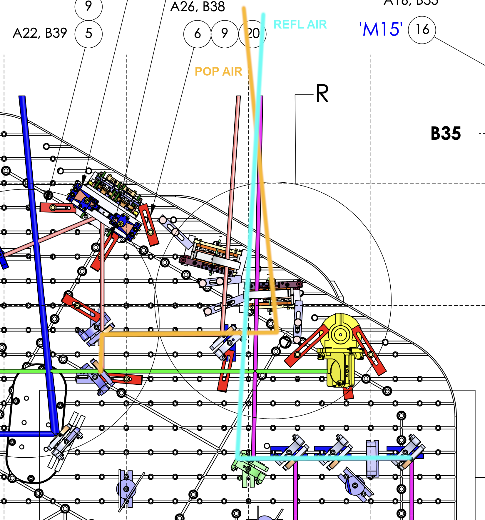
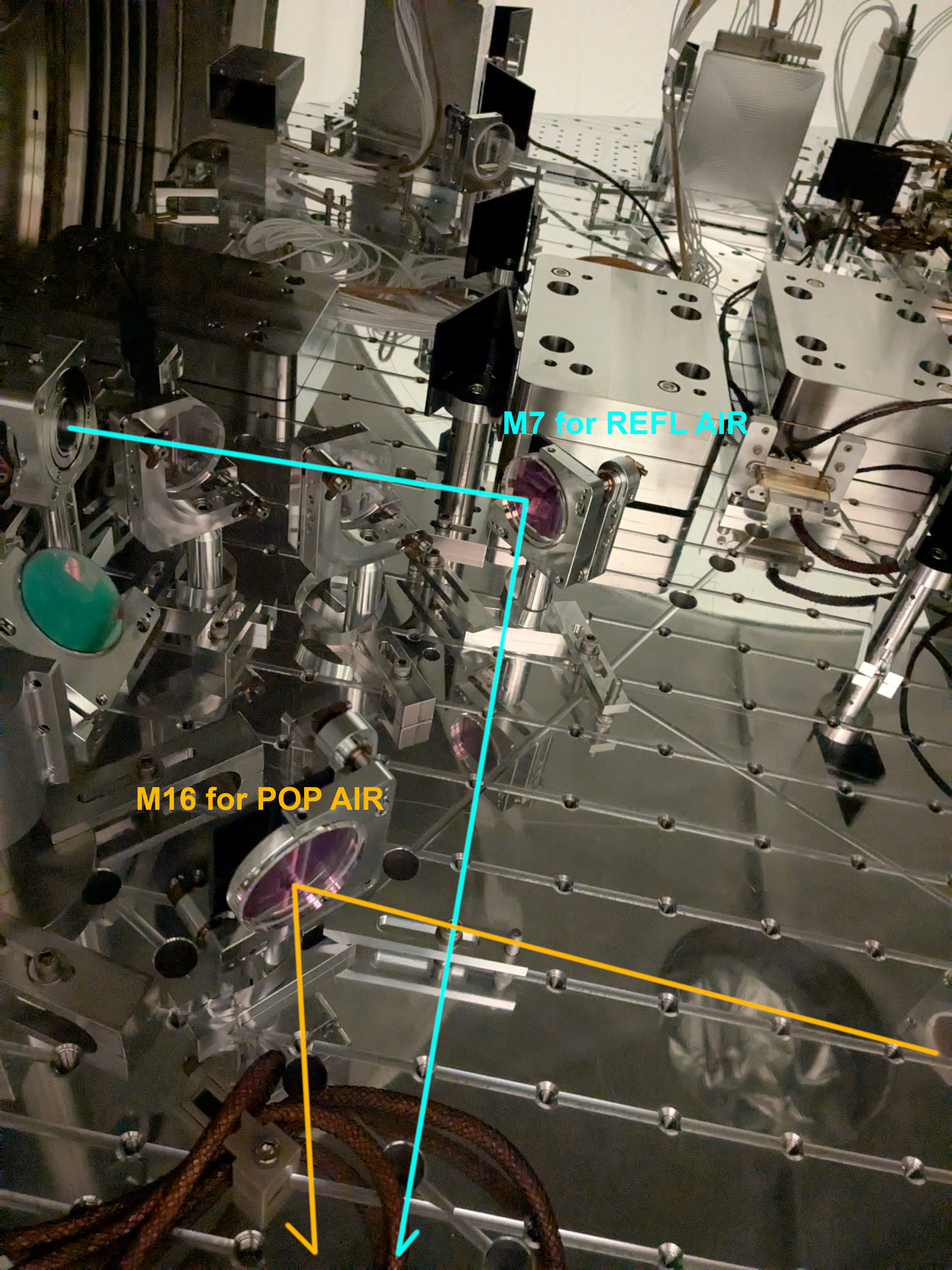
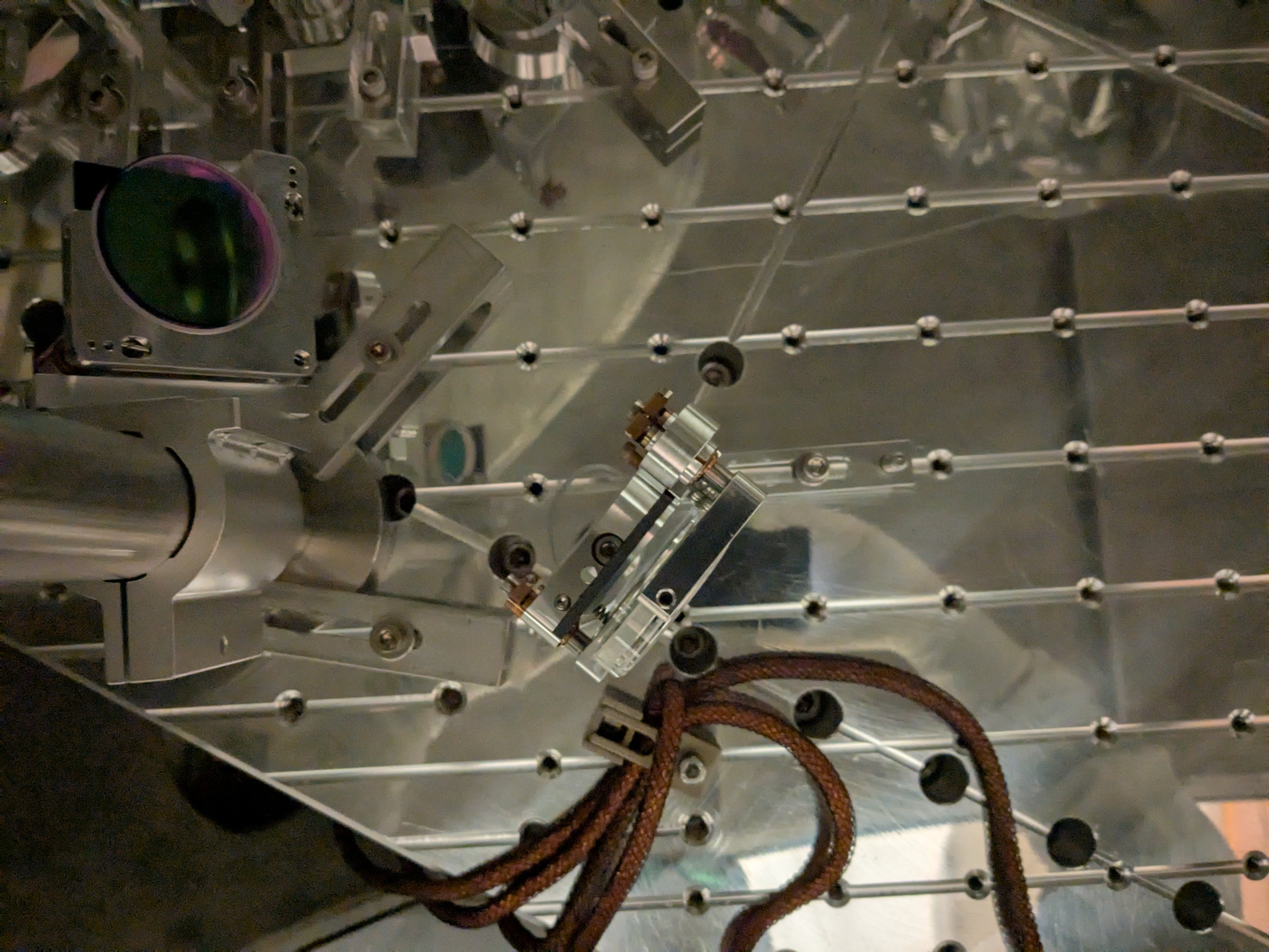
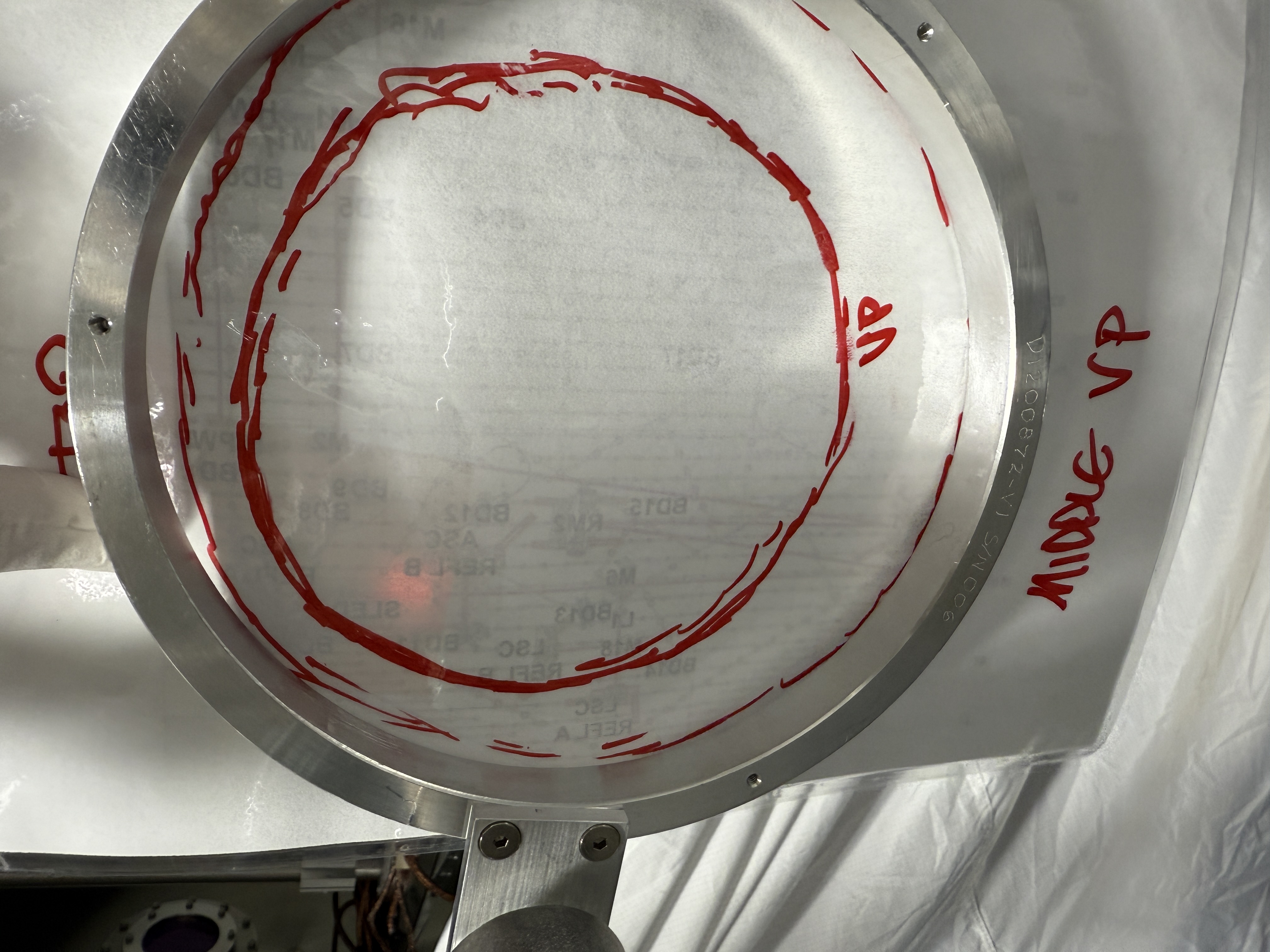
PSL ALS: we decided that the PSL ALS path was too close to the edge to the VP (84334) we tried moving M13 so the beam traveled in-between M11 and L2 but this didn't give enough separation at the bottom pericope mirror of ISCT1. We then put M1 back to a similar position to wear we started an decided that it was good enough away form clipping the VP. Photos attached of M15 location, beam on M15, beam next to L2, VP simulator, UPM, LPM.
The logic of the REFL diverter has been changed to alternate beam. This required a restart of the slow controls software.
Before lunch, Tyler, Oli and Betsy removed ISCT1 and the VP simulator.
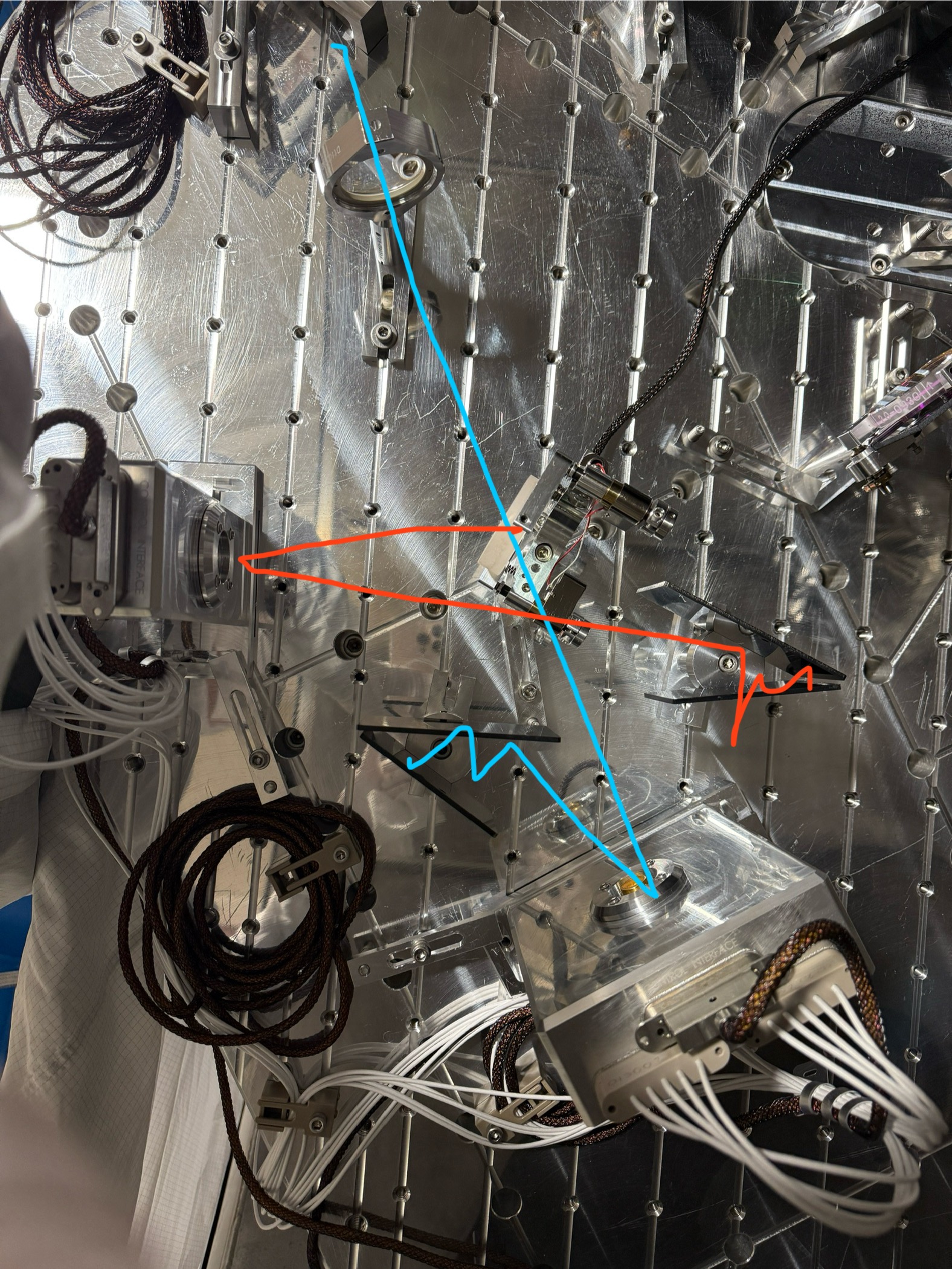
POP Beam to diodes:
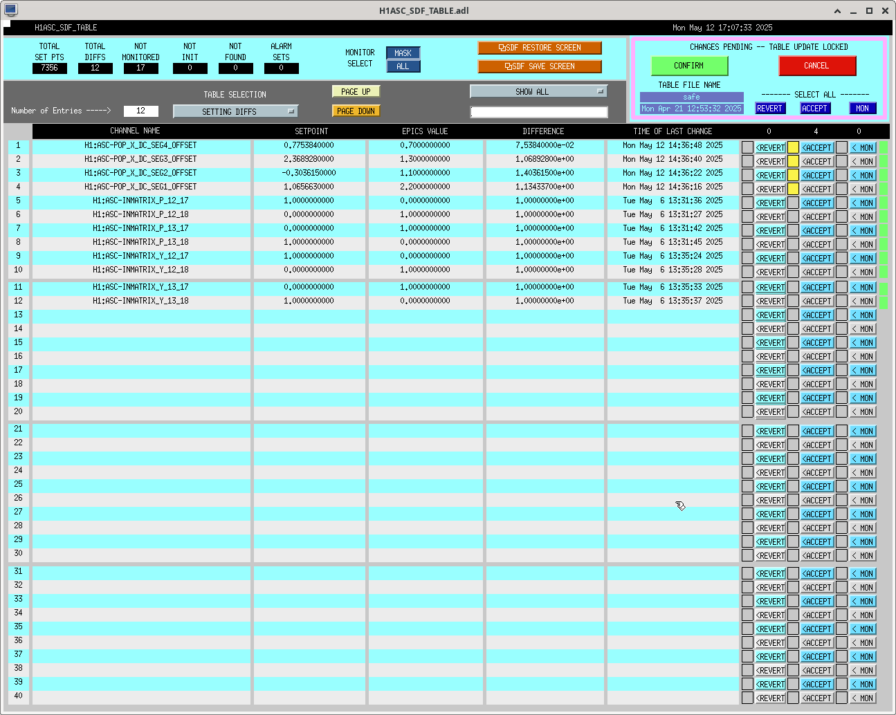
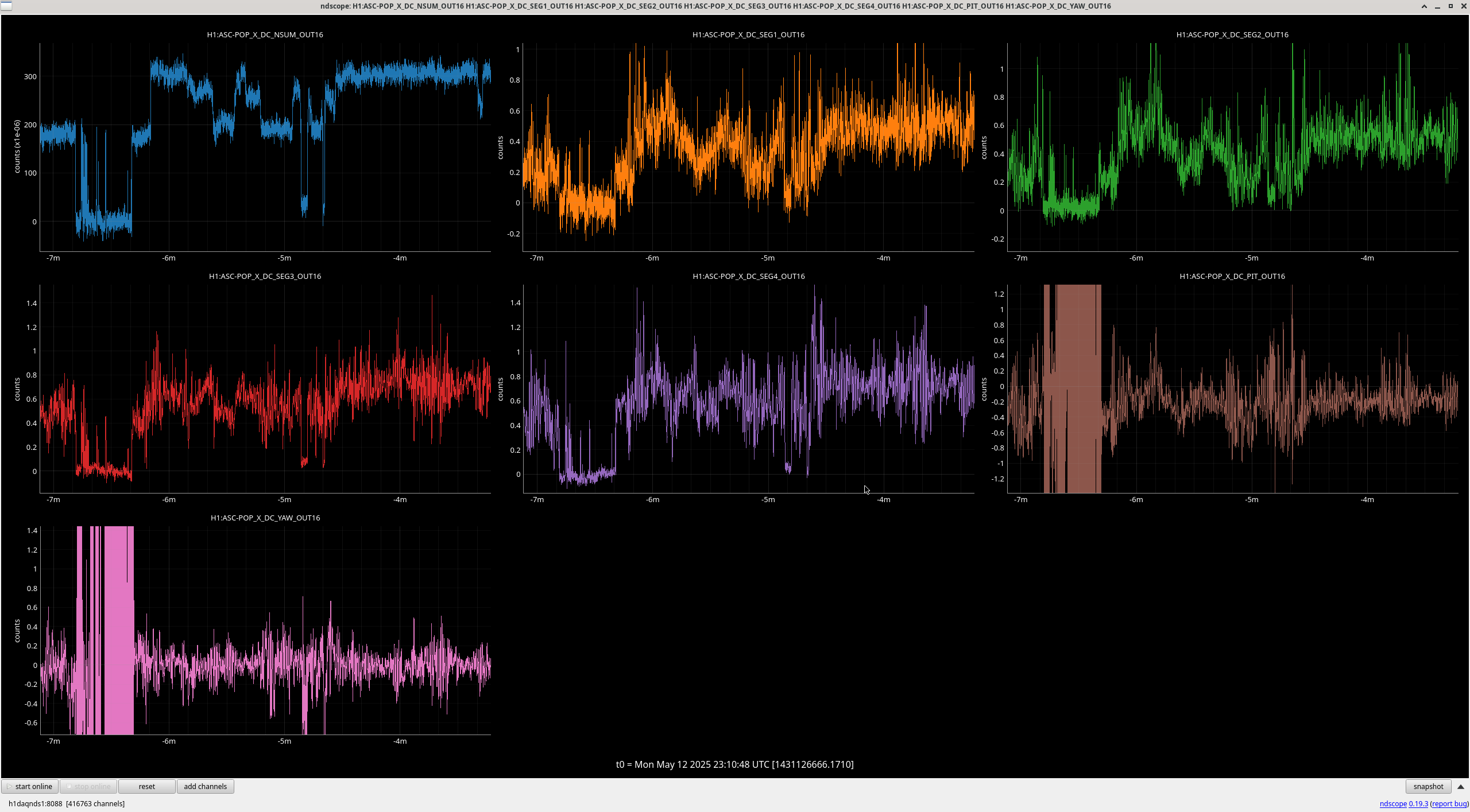
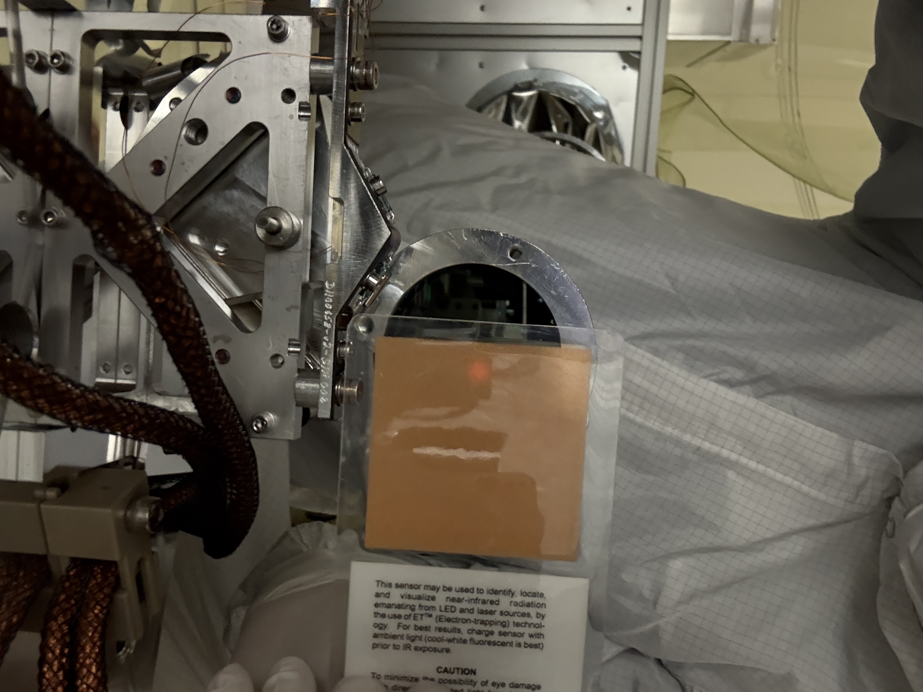
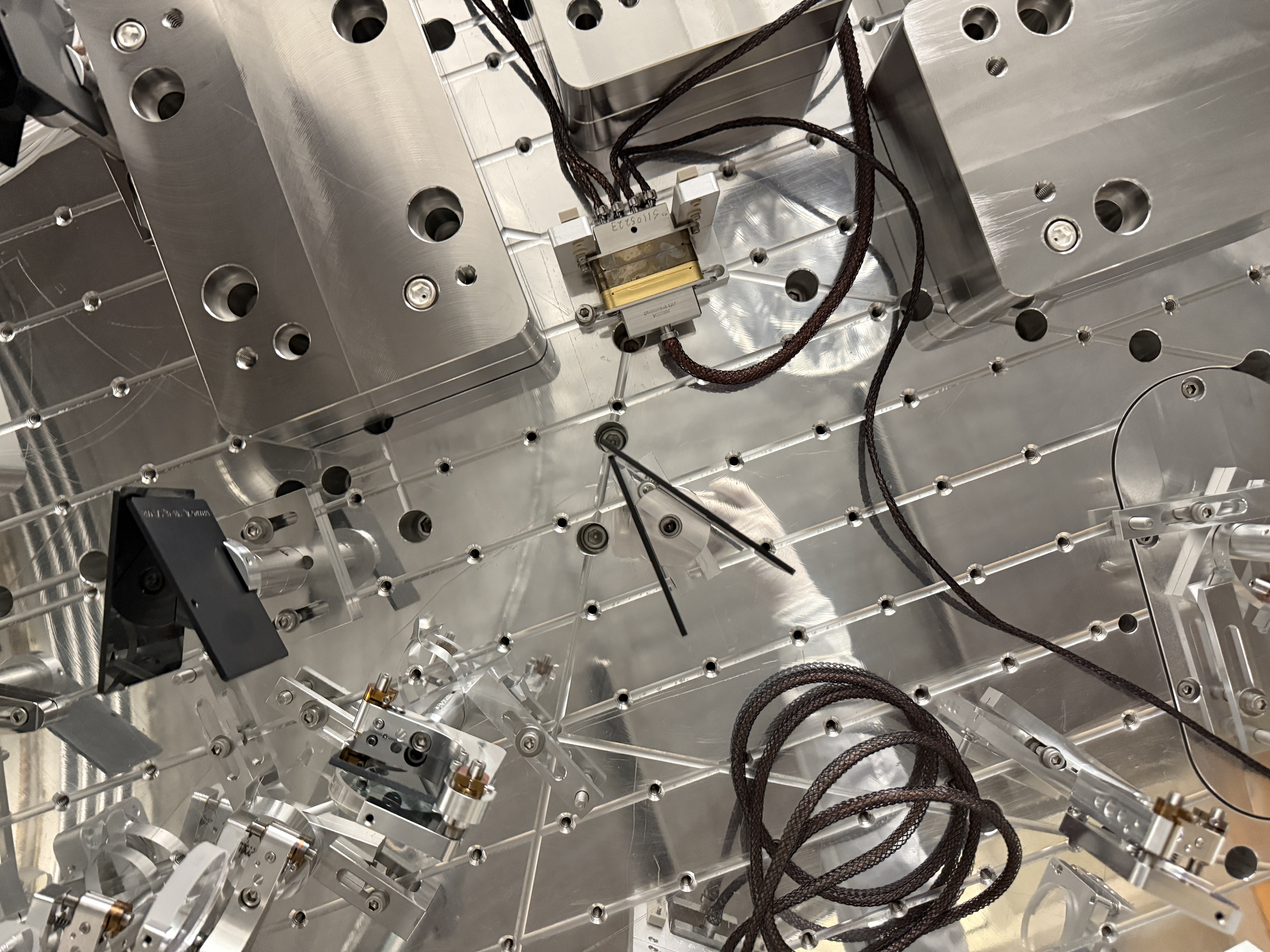
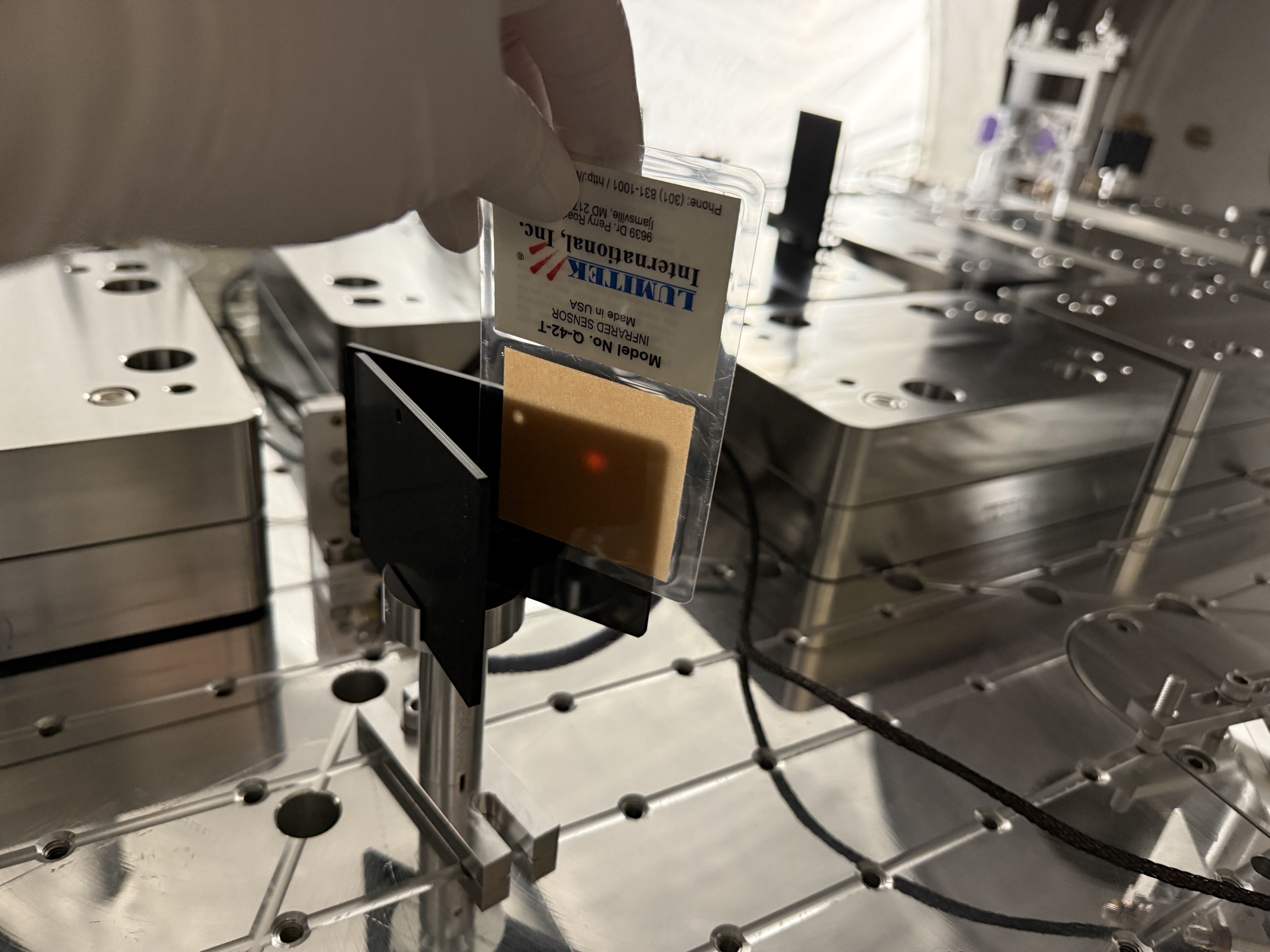
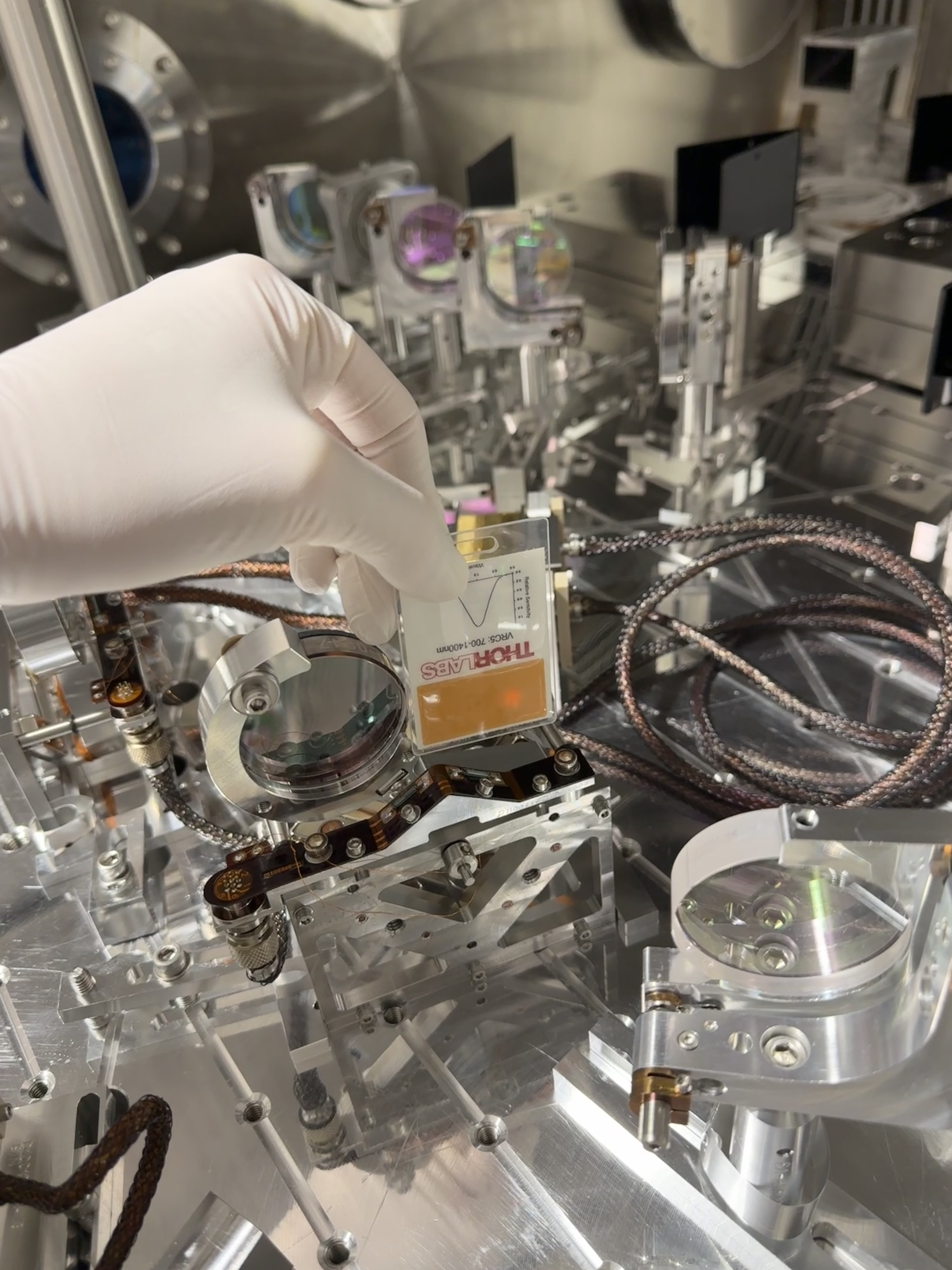
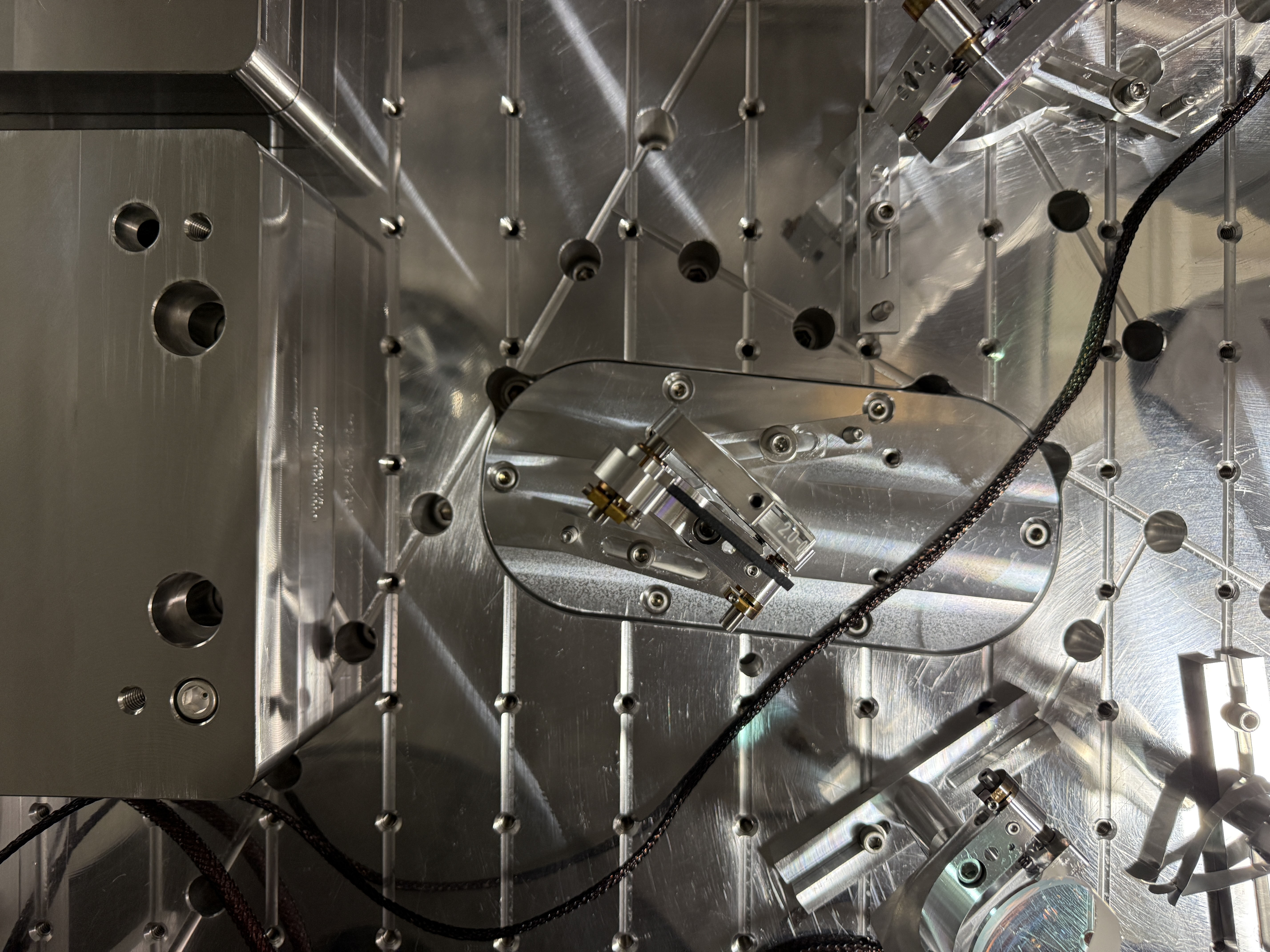
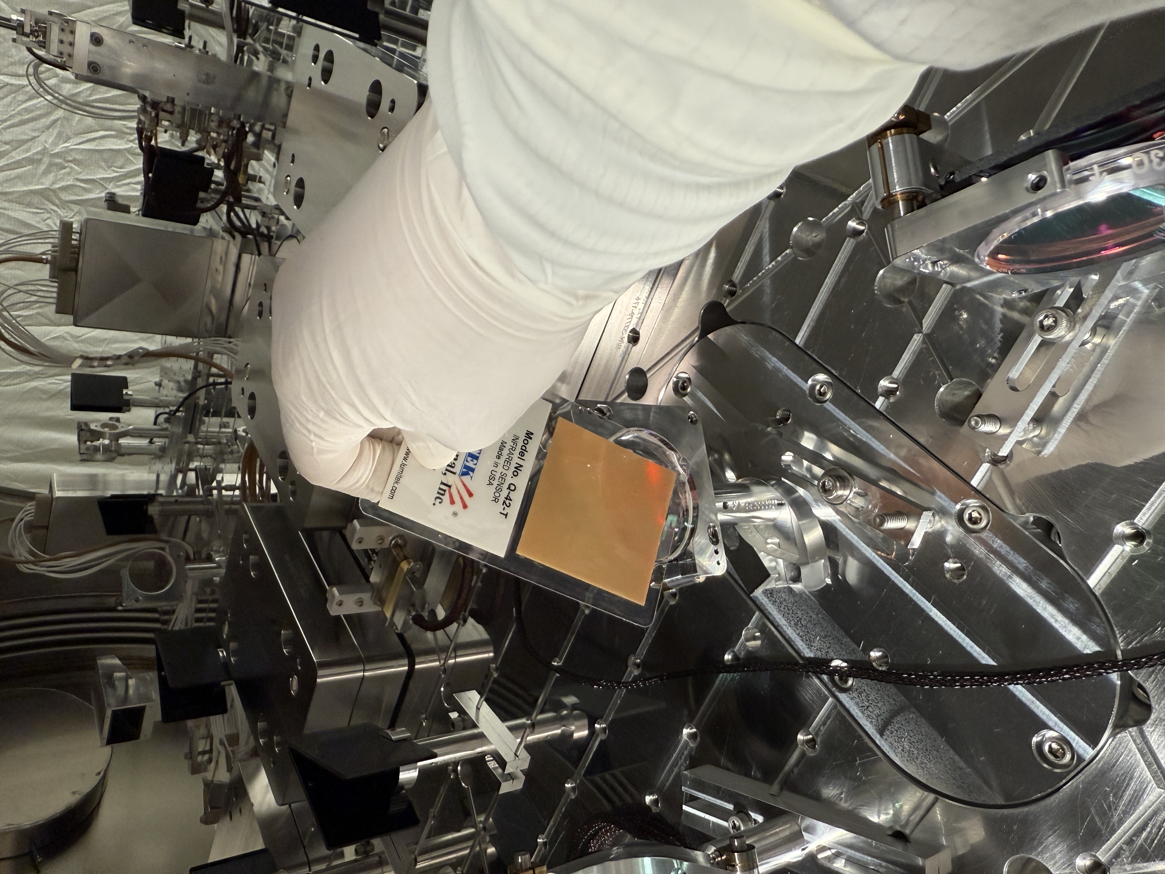
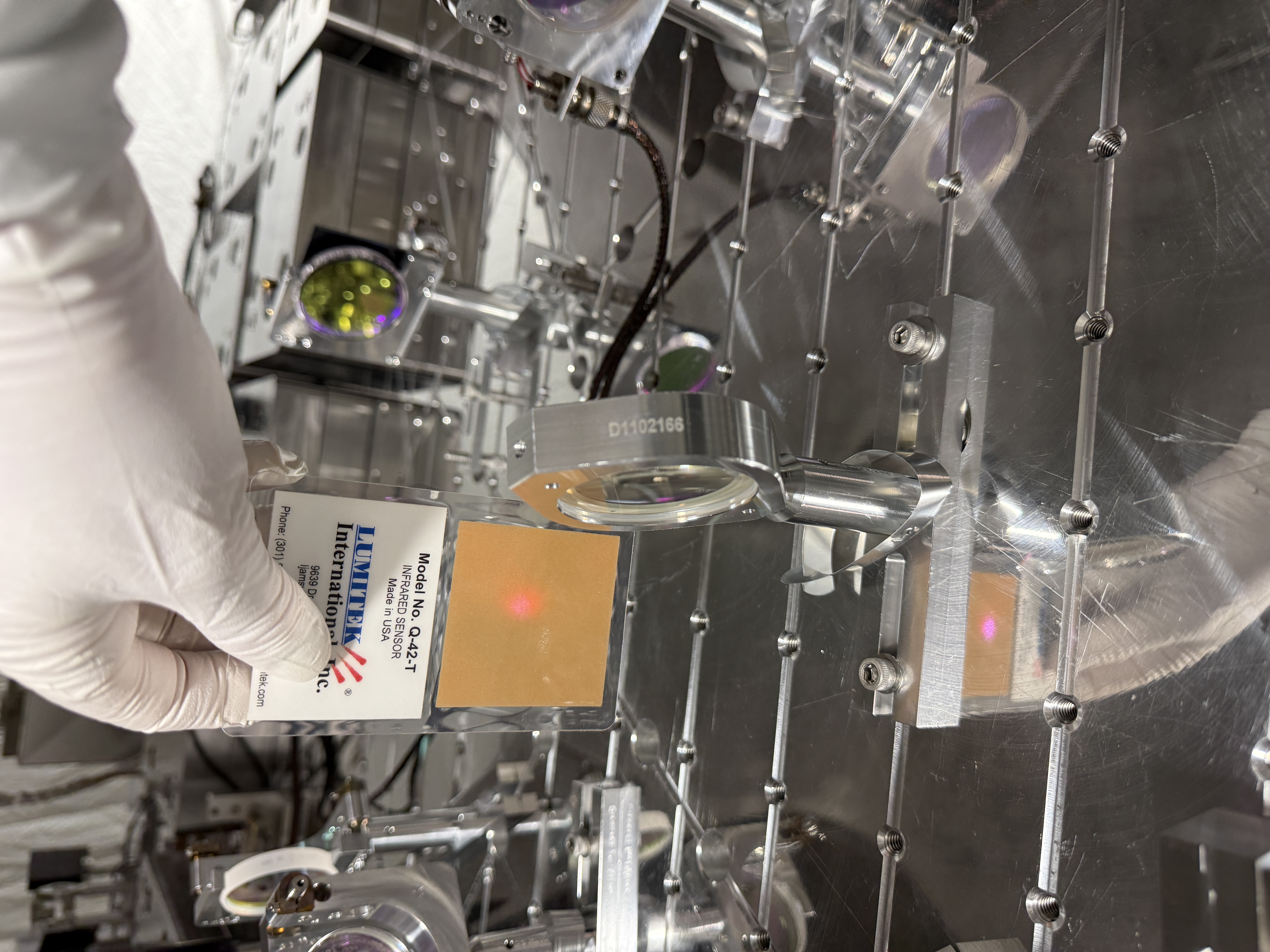
Jennie and I aligned the POP beam onto the POP X ASC diode (using flashes then single bounce, with 20W in). We needed to adjust the dark offsets (they are about the same size as the 1.5uW single bounced beam), sdfs accepted in safe attached, properly need to be redone and saved once we get to observe. All segments responded to the beam and a flashlight and we centered the beam in pitch and yaw using PM1 (alignment sliders P:100, Y:50).
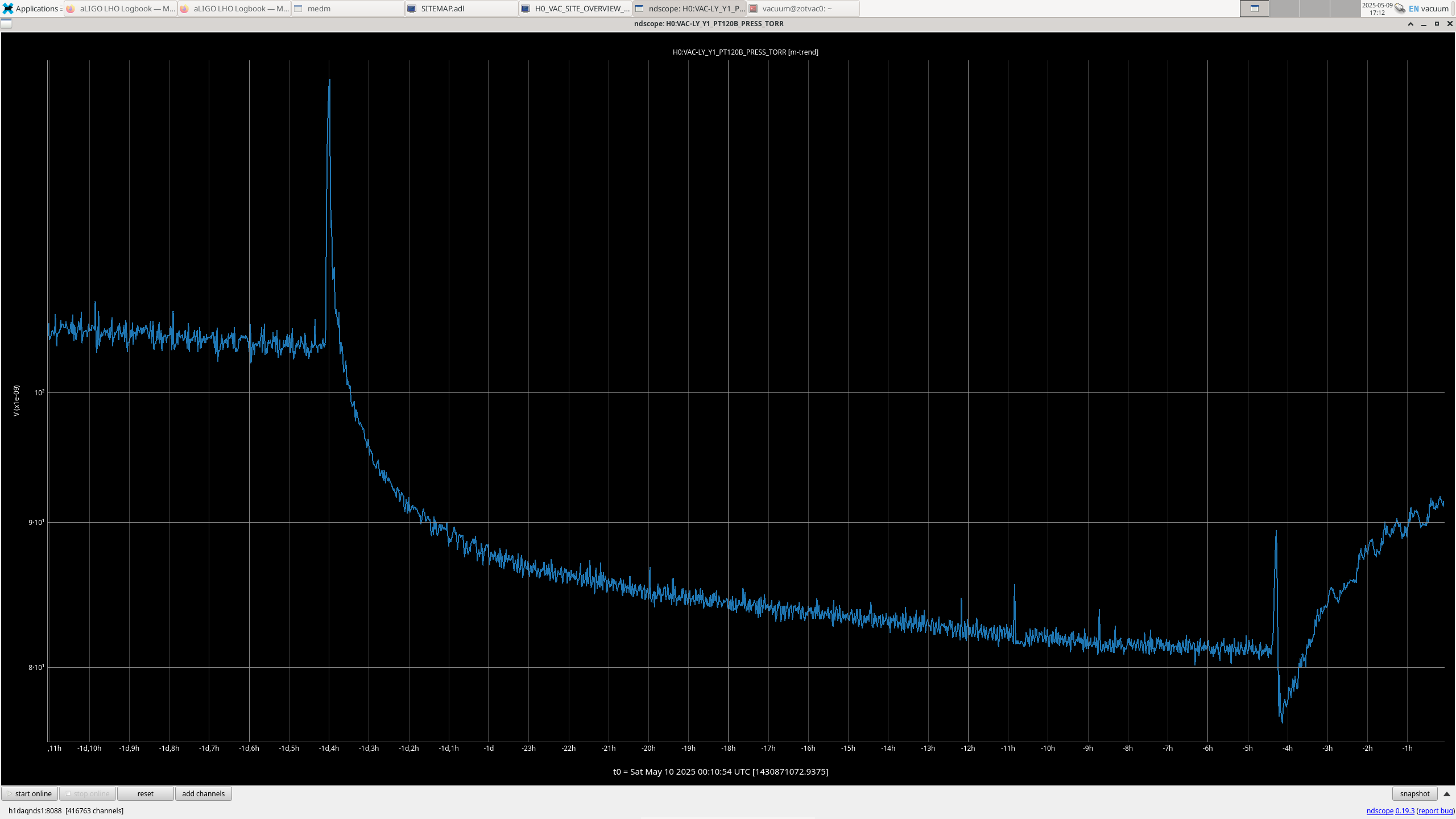
Elenna and I aligned the POP beam onto the POP A LSC diode (using flashes then single bounce). We checked the POP LSC picomotor was working as expected. Checked beam was centered on the diode by it was centered by going to the middle of the edges of the diode. All segments responded to the beam and a flashlight and we centered the beam in pitch and yaw using PM1, ndscope. Note that we'll want to check this again tommor0w as we need to offload the picomotor in yaw as it doesn't have much range left.
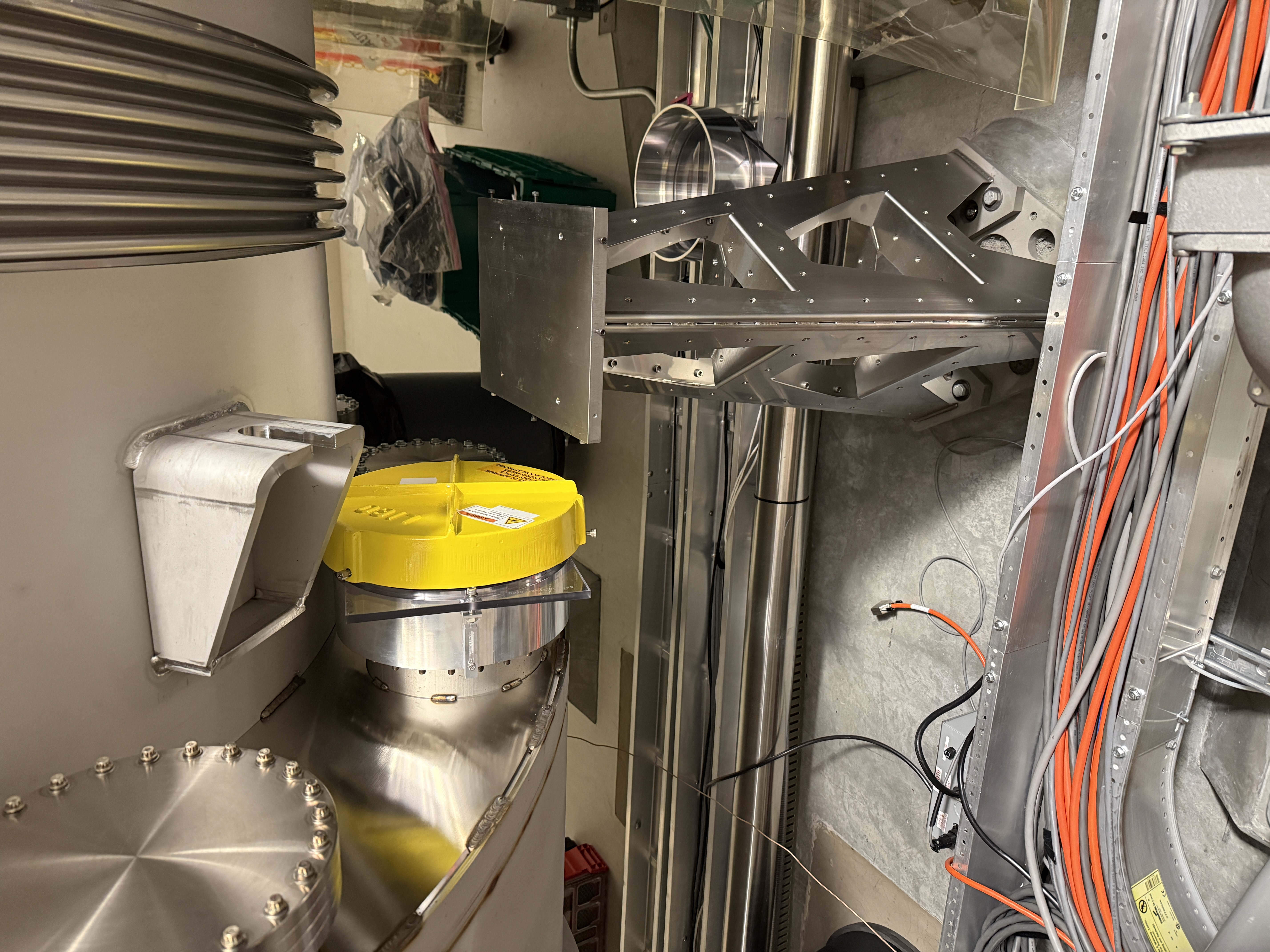
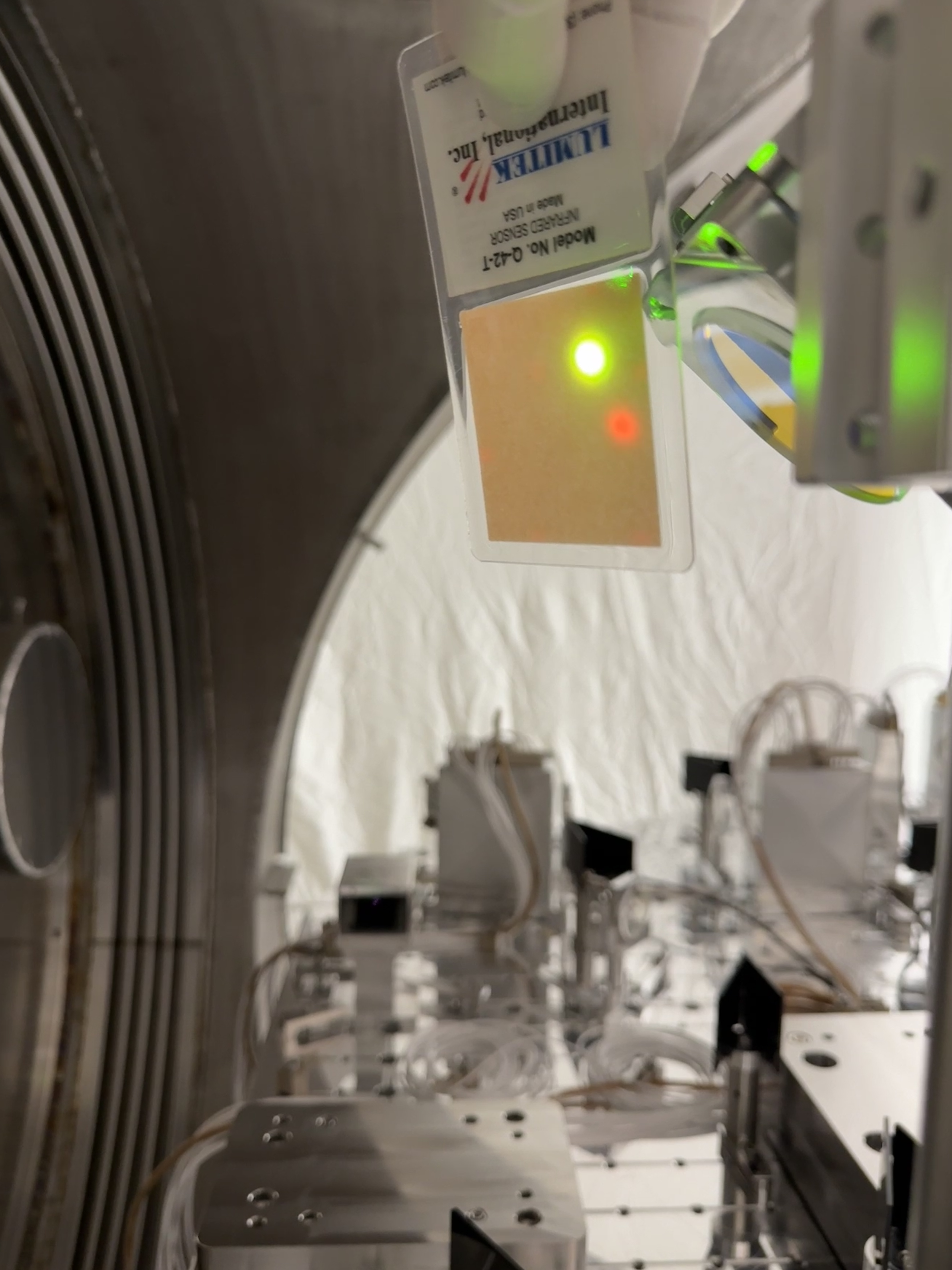
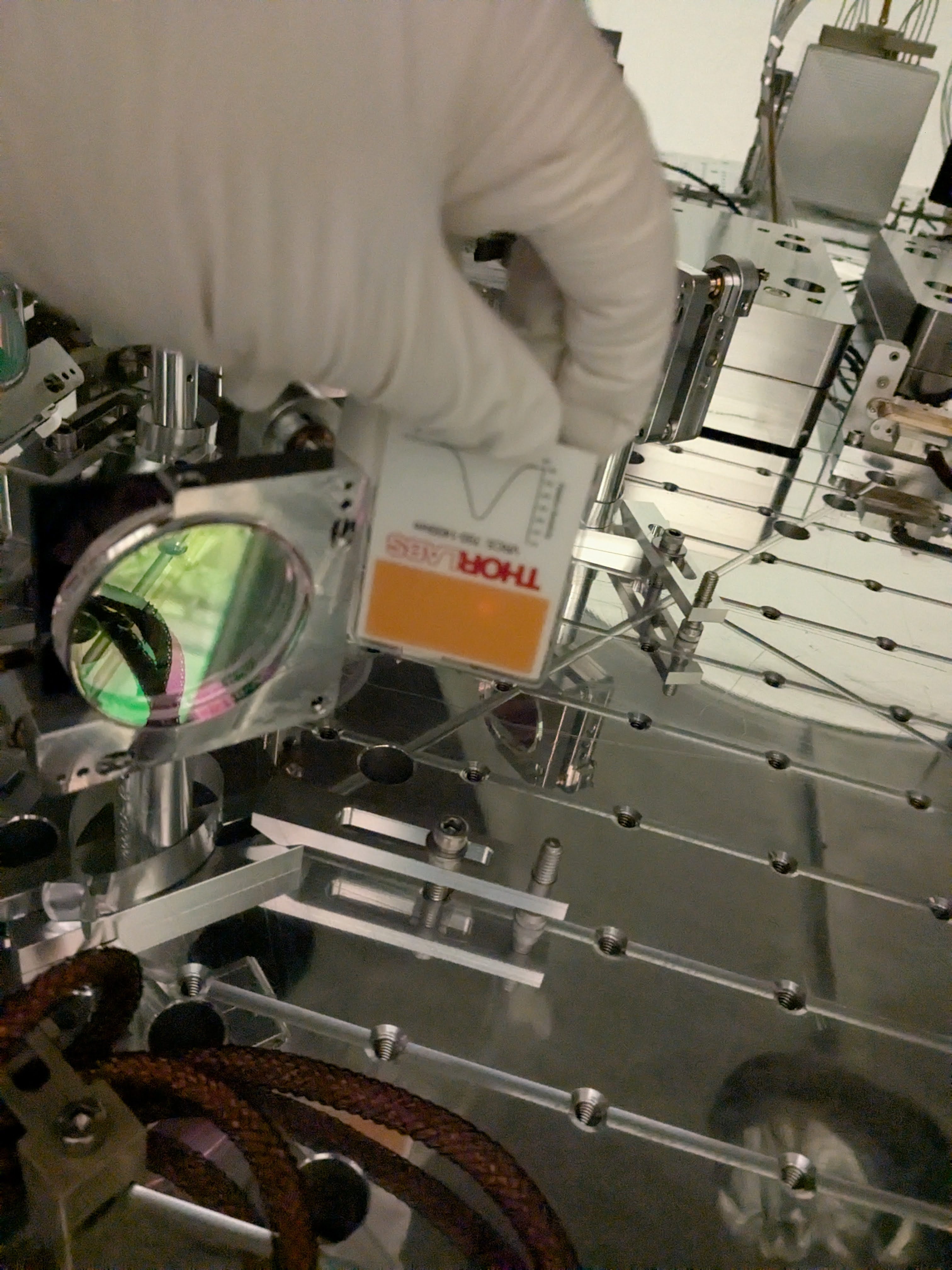
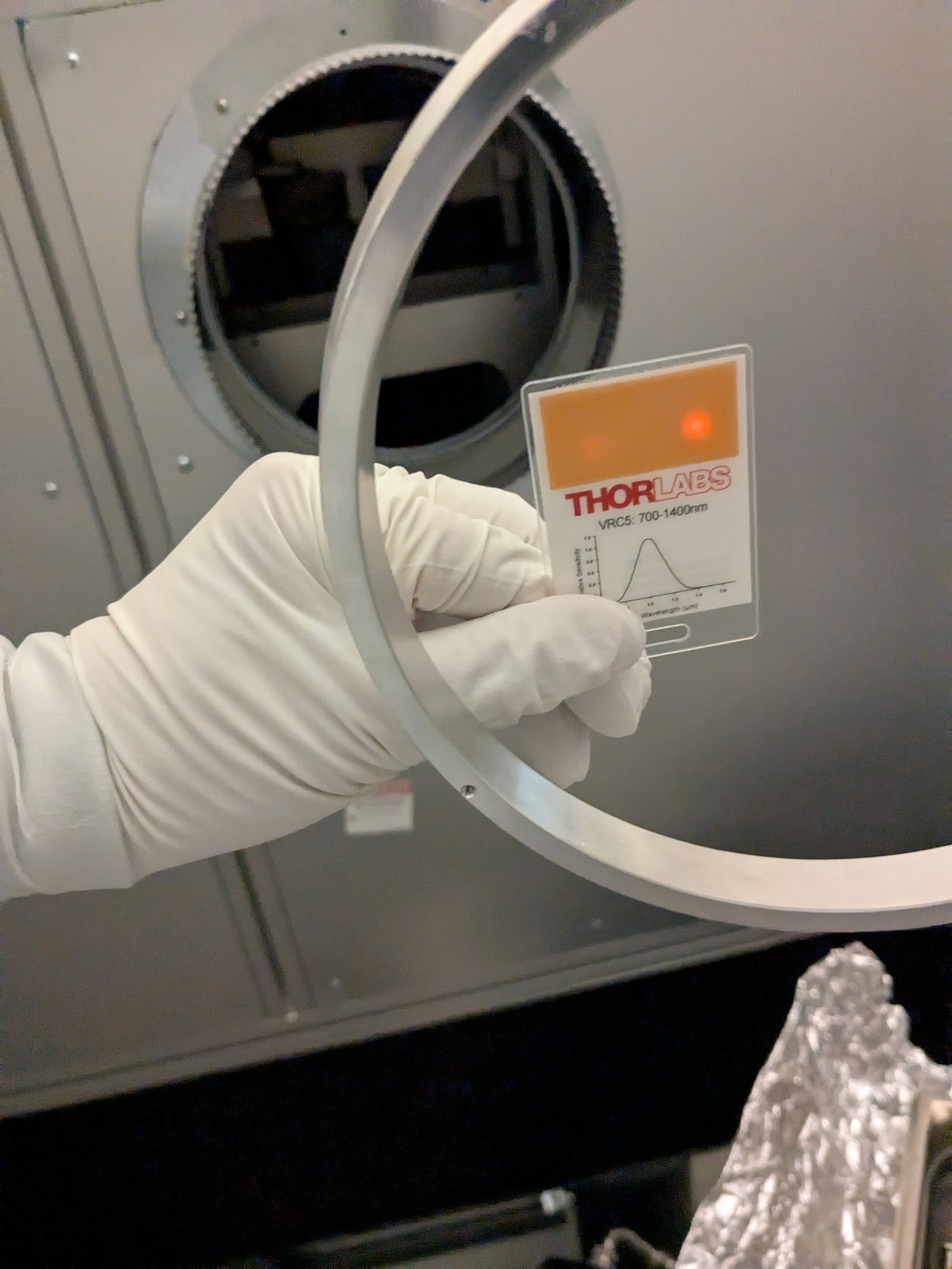
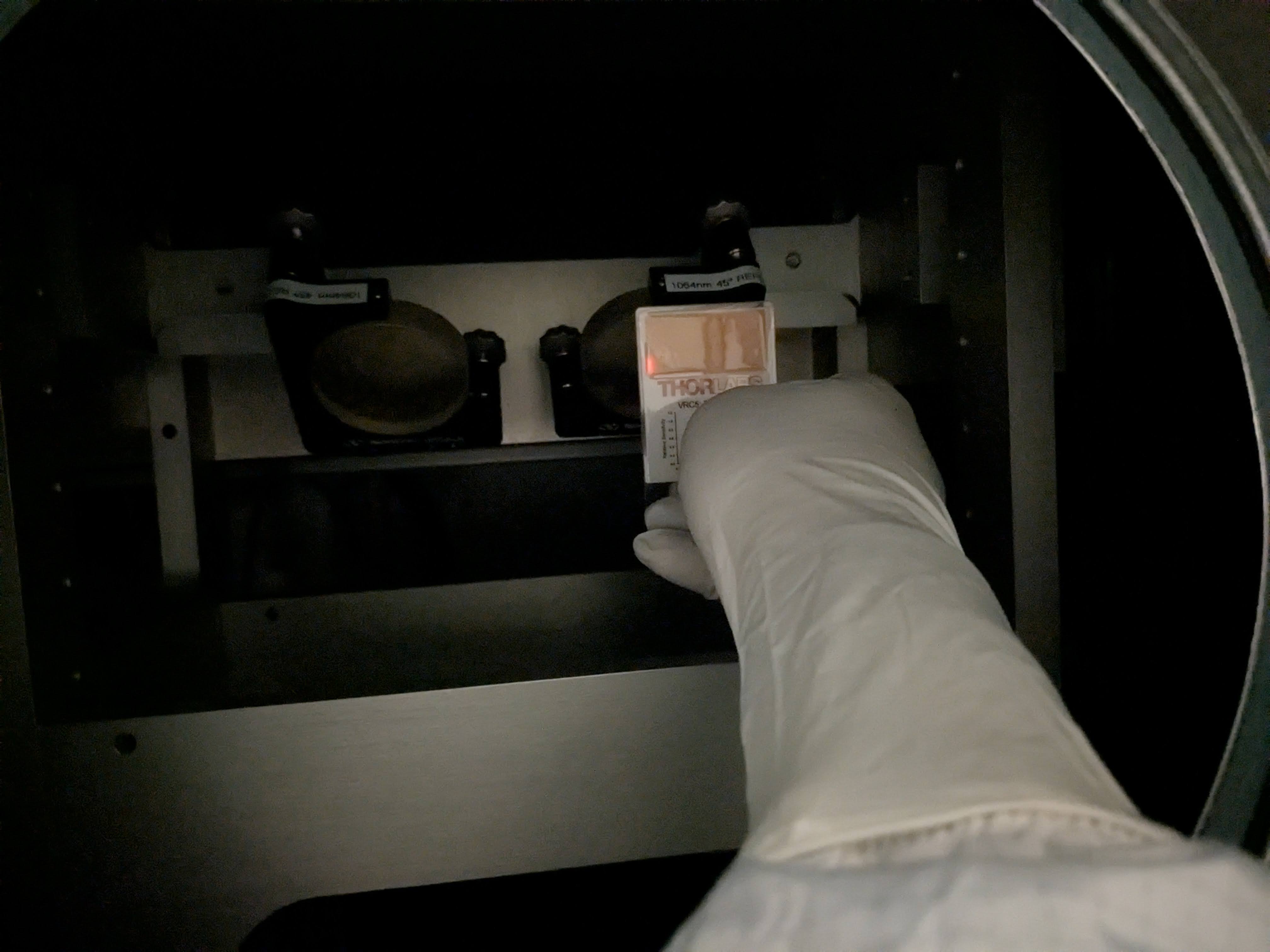
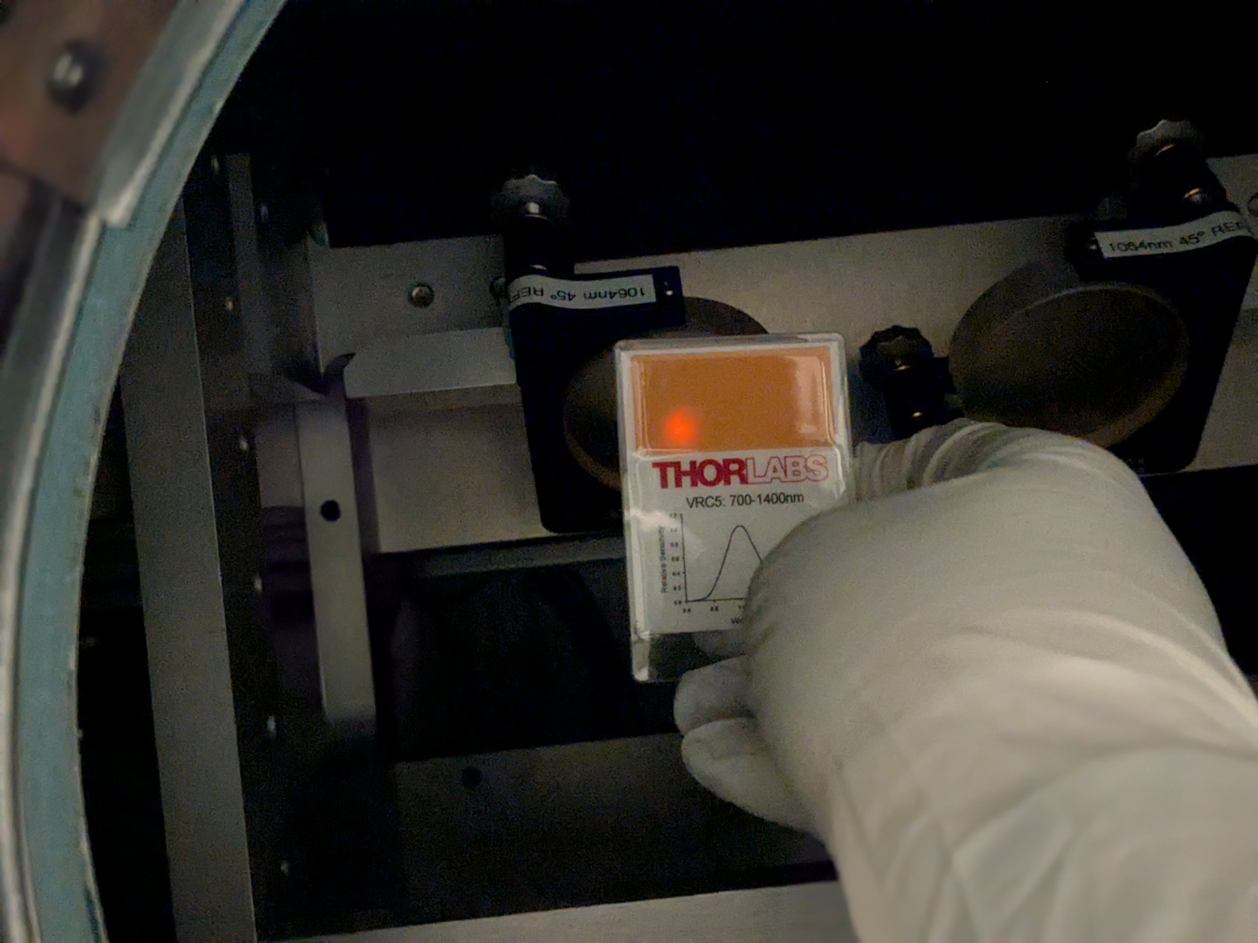
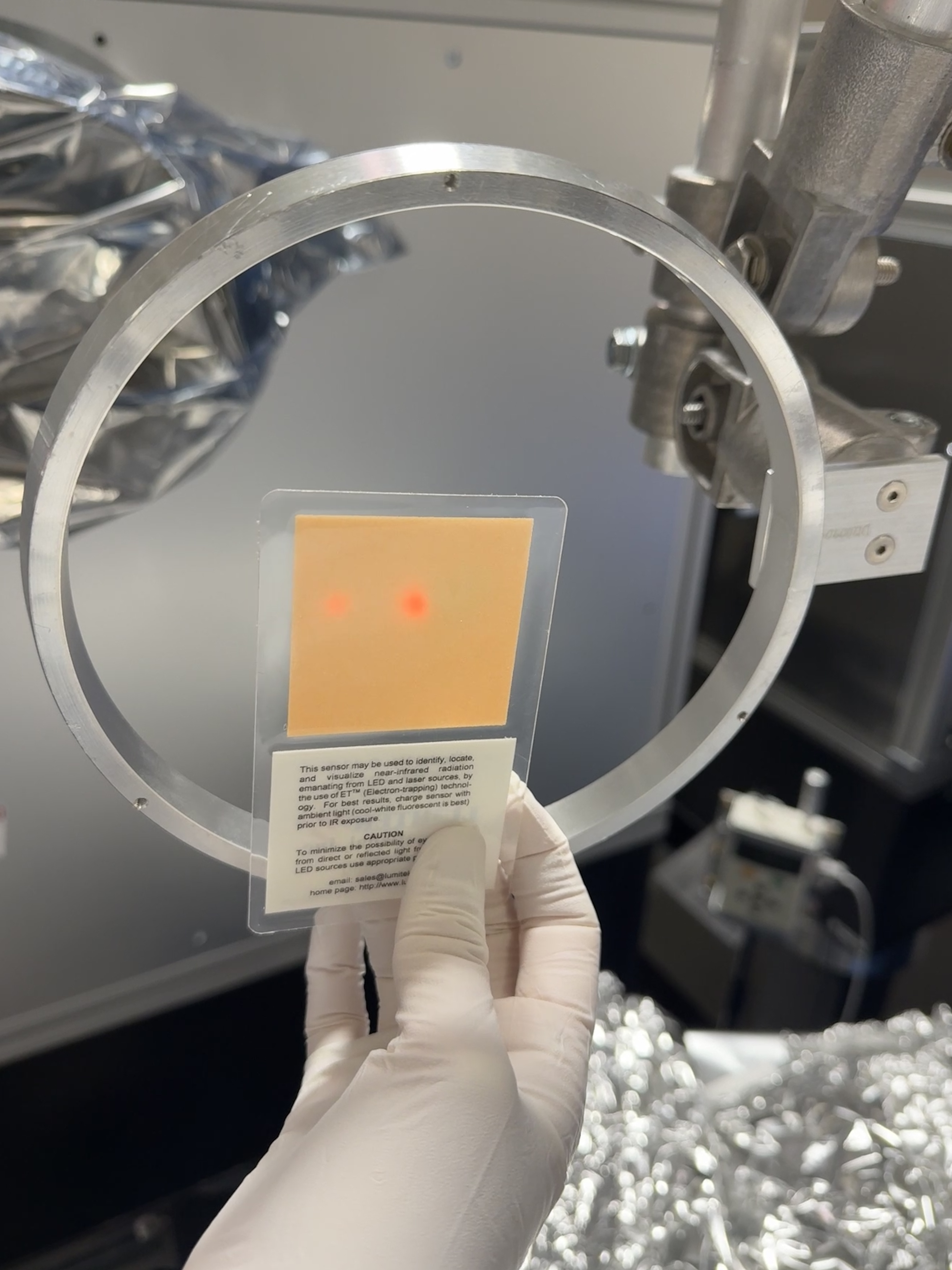
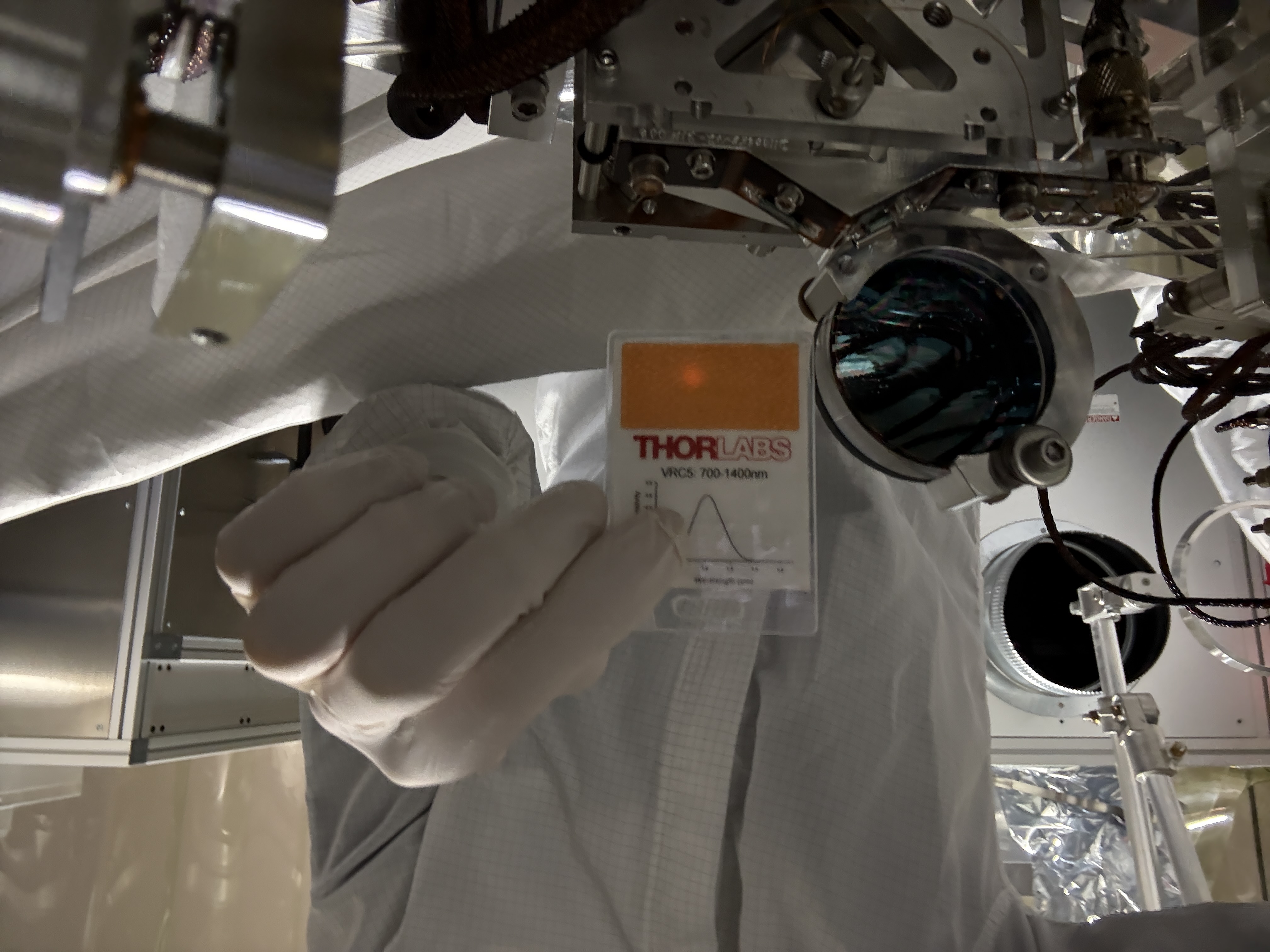
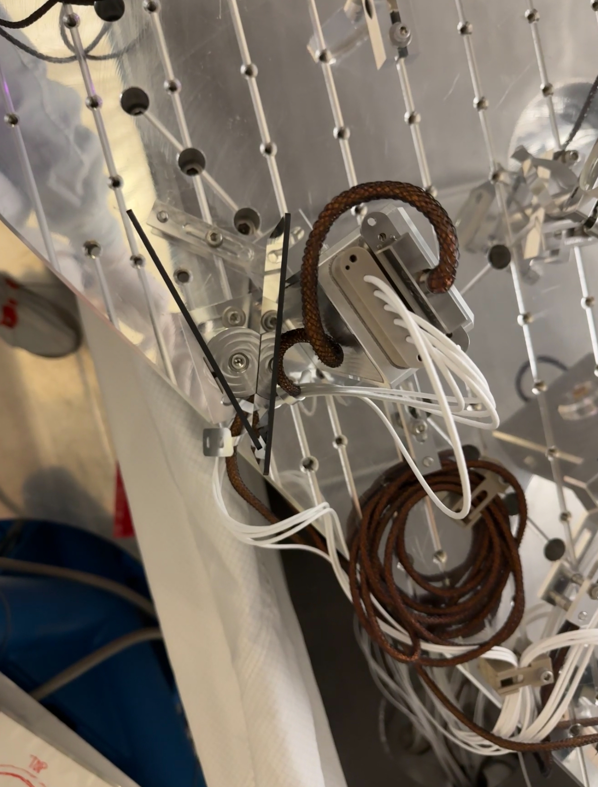
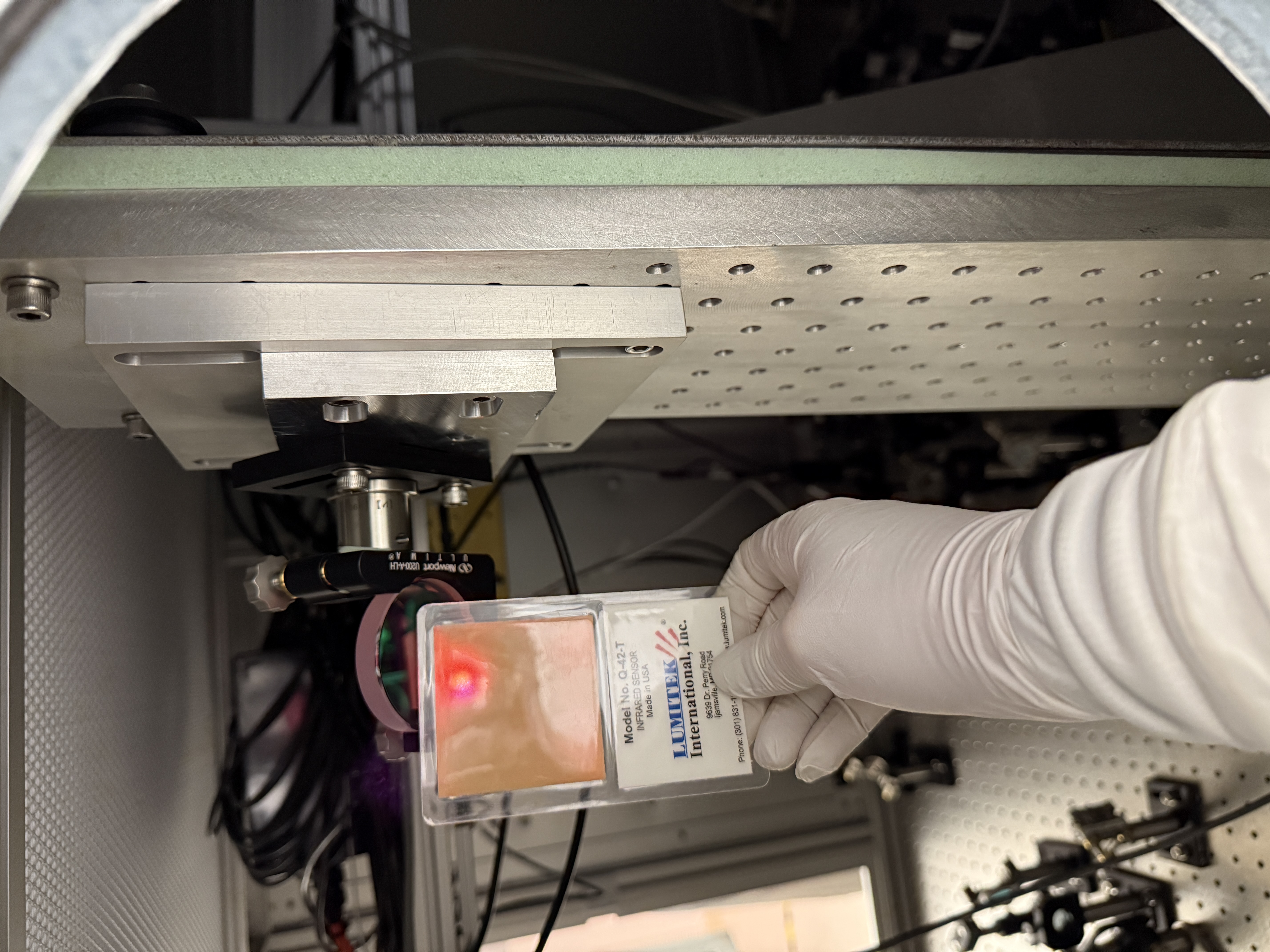
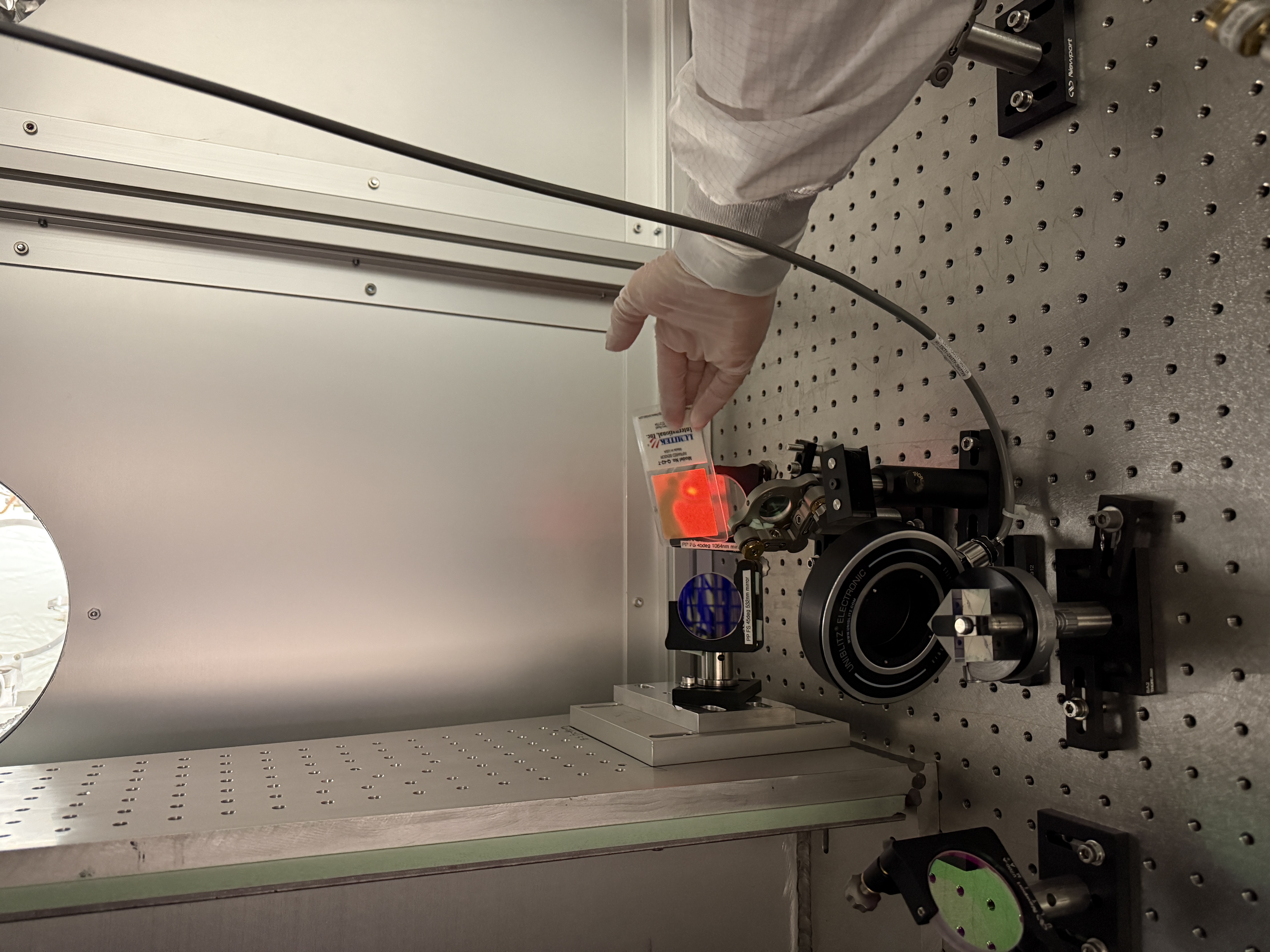
We couldn't see the didoe reflected beams (using POP flashes, sensitive IR card and IR viewer) so I dead rekon'ed the positions of beam dumps BD1 and BD2, see attached photo.
Leaving IMC locked with 2W in.
Still to do: offload POP LSC pico and check alignment, place BD6a, 6b, 7, 9 (couldn't see beams easily tpday at 2W), final checks (see other alog).