We have had plenty of things wrong in the IFO since we used bad safe.snaps to restore after the power outage last wensday. (A2L gains, missing ASC notches, ETMY bias was accidentally flipped, plenty of dark offsets changed, some violin damping was on with the wrong filters engaged ect...)
This morning Jenne, Kiwamu and Evan helped me to clean this up so we are nearly back in the observe state from O1, with only intentional changes like the LSC feedforward and sending MICH to PR2, which we have accepted.
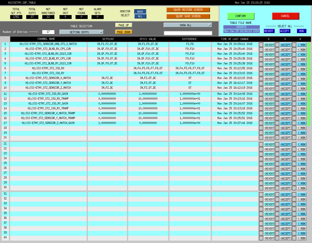
There are a few things remaining red:
The bias is flipped on ETMY, and the gain in L3 DRIVEALIGN_L2L (which compensates for the bias flip). It might be that we have messed up the calibration by doing this flip accidentally, but we were planning on doing it soon anyway.
I've also implemented a version of the scripts from LLO that load down.snaps in SDF when the IFO goes down, and observe.snaps when we reach nominal low noise. So far we only have saved a few down.snaps, but if we add more and keep them up to date this should be alot easier in the future since we won't need to be locked to see what differences we have.