TITLE: 05/09 Day Shift: 1430-2330 UTC (0730-1630 PST), all times posted in UTC
STATE of H1: Planned Engineering
INCOMING OPERATOR: None
SHIFT SUMMARY:
Bees:
There is a box potentially full of bees sat right next to a spool of wire and a chair at EX as the Bee keeper is trying to remove the beehive from the wire spool.
There is still a bee swarm near the gate as well.
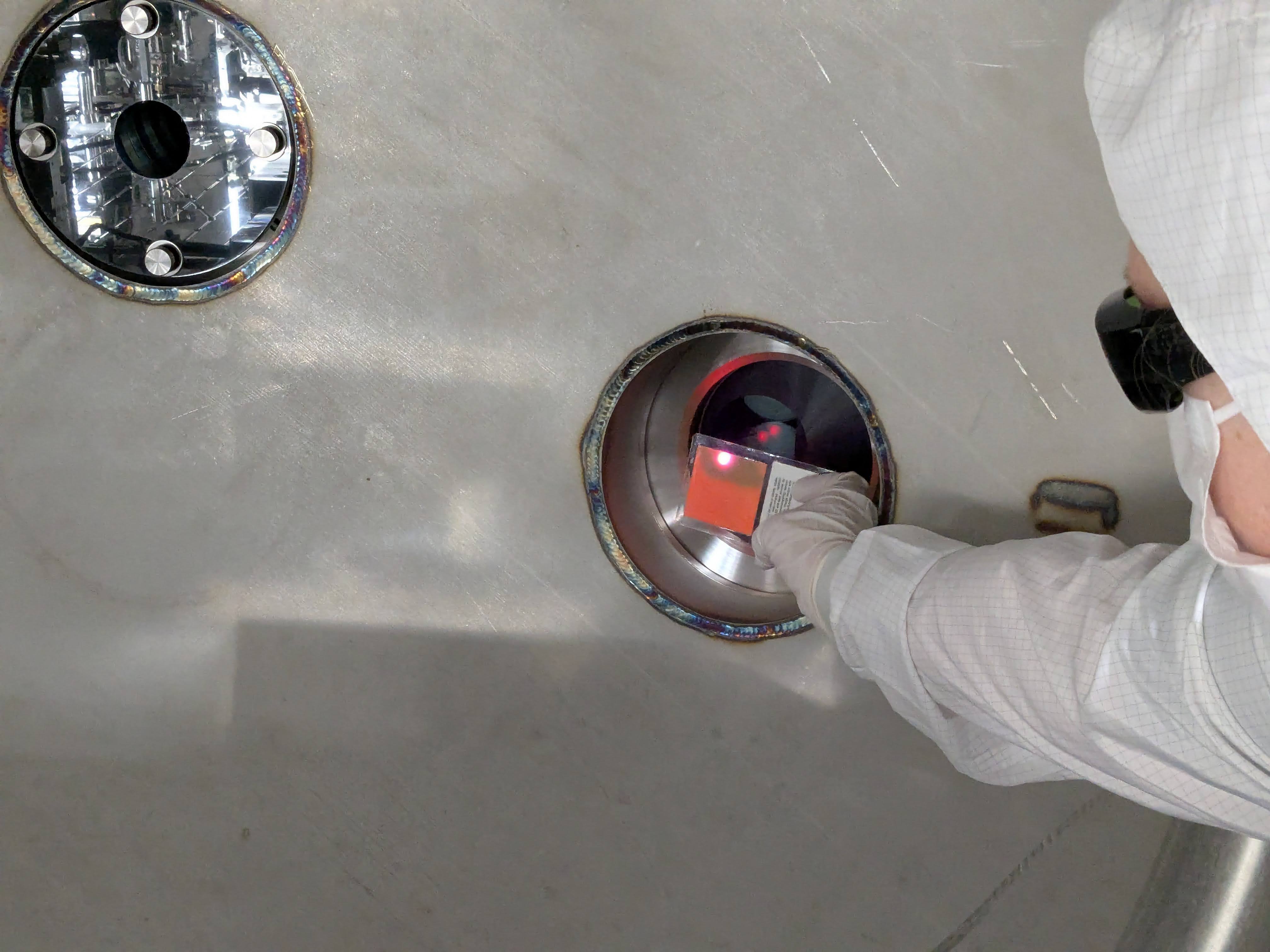
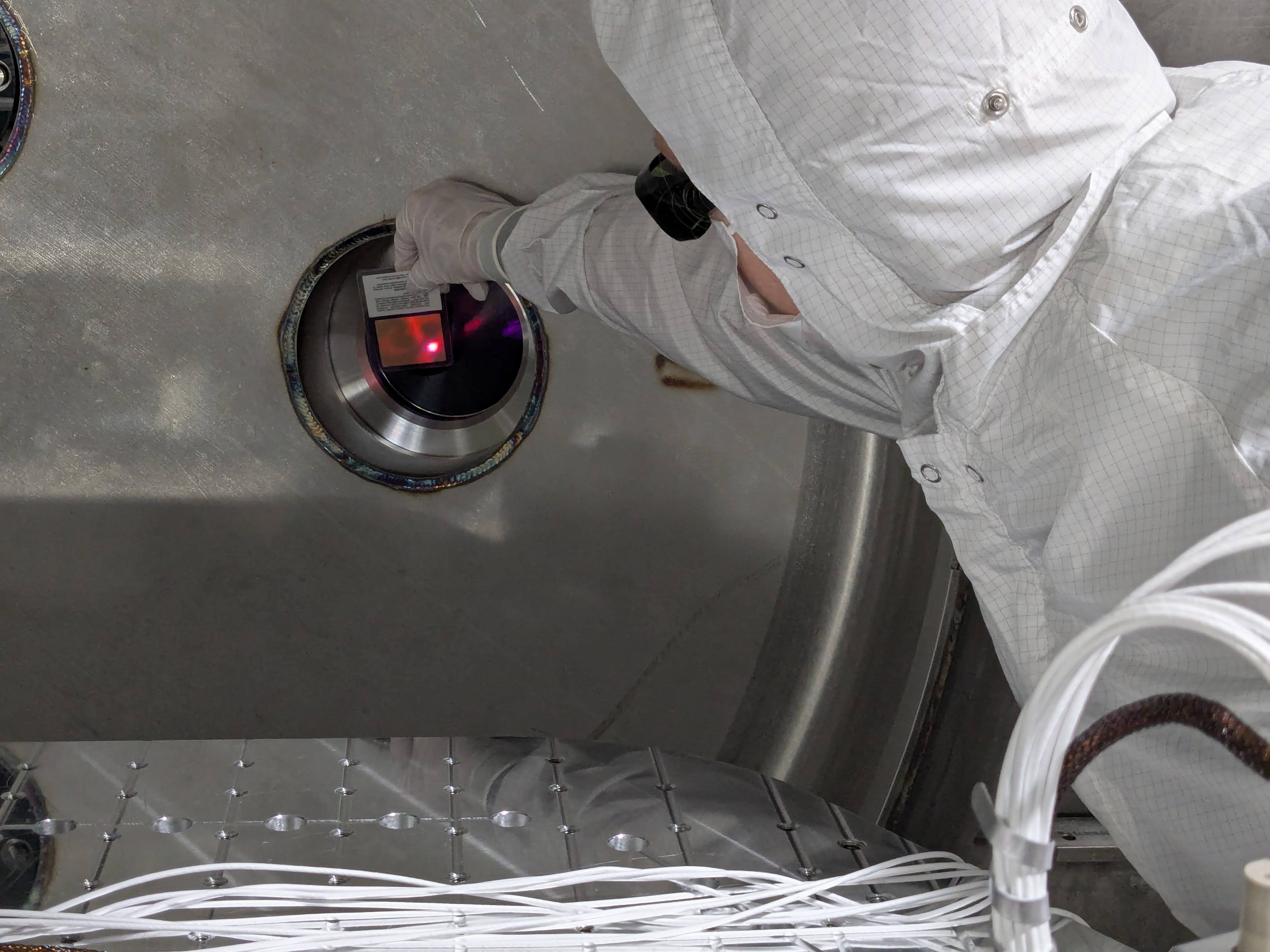
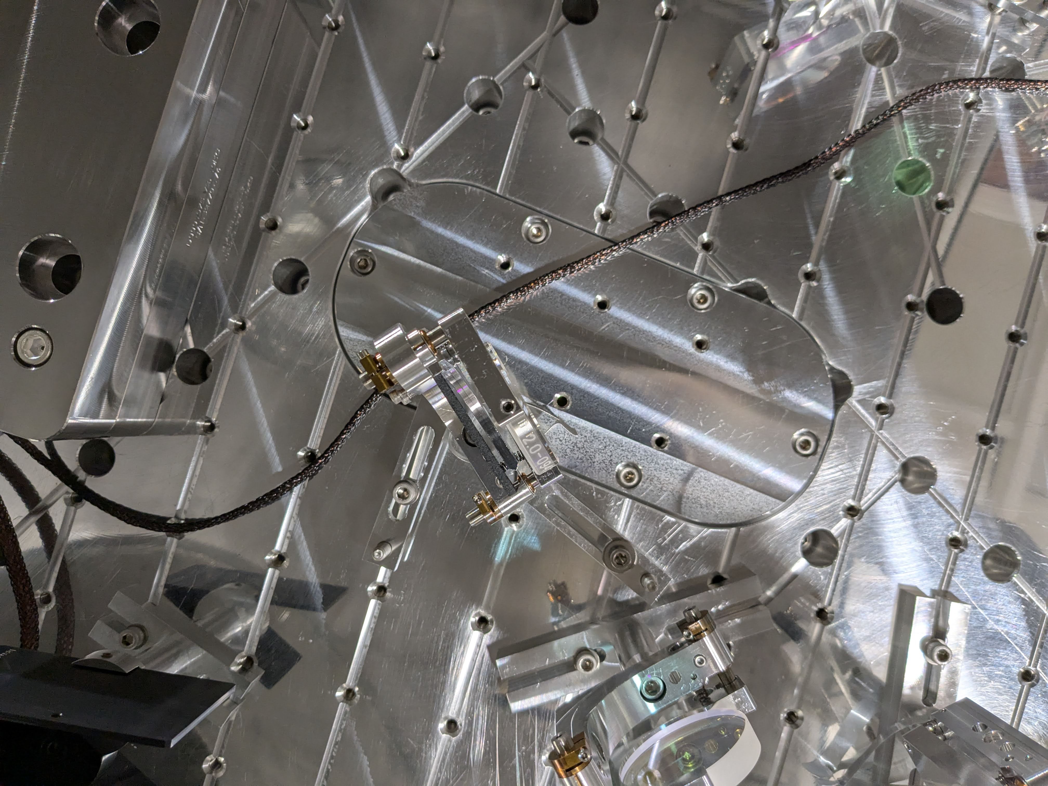
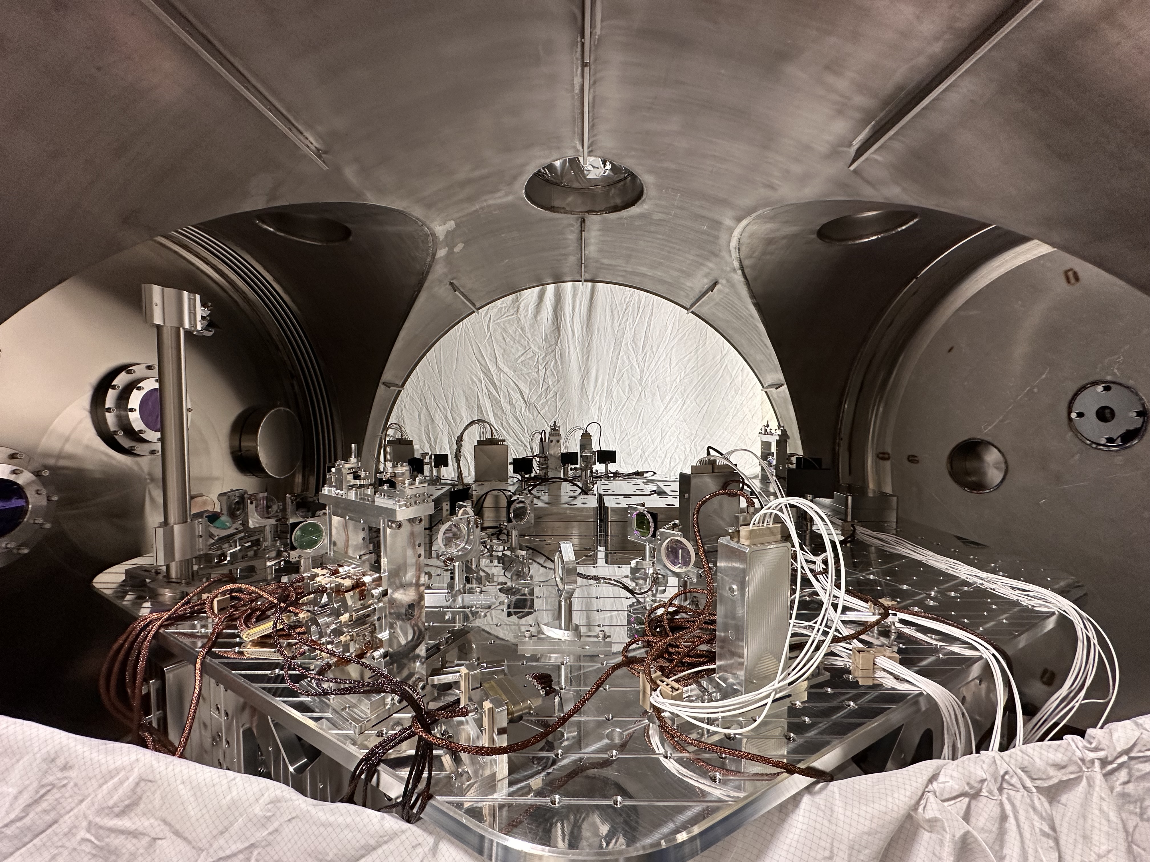
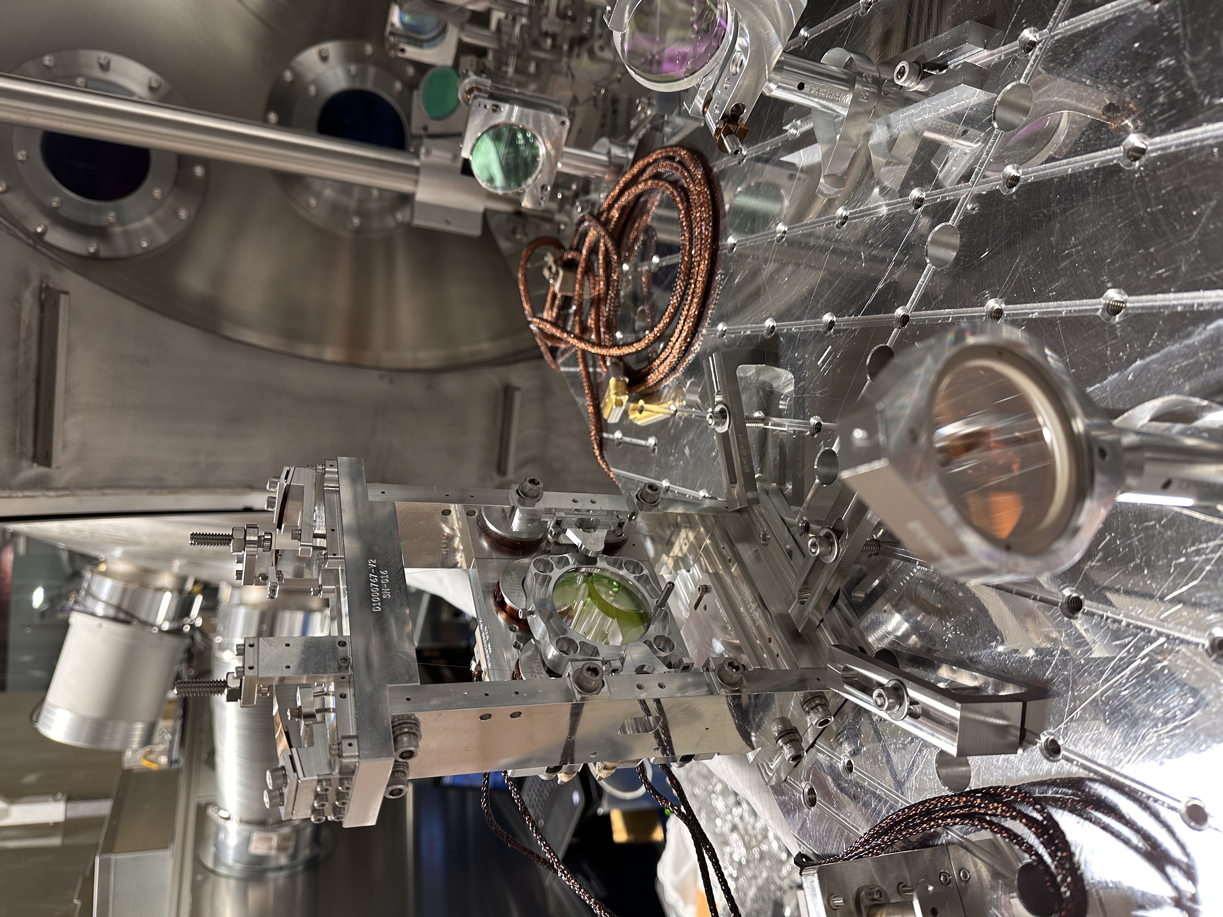
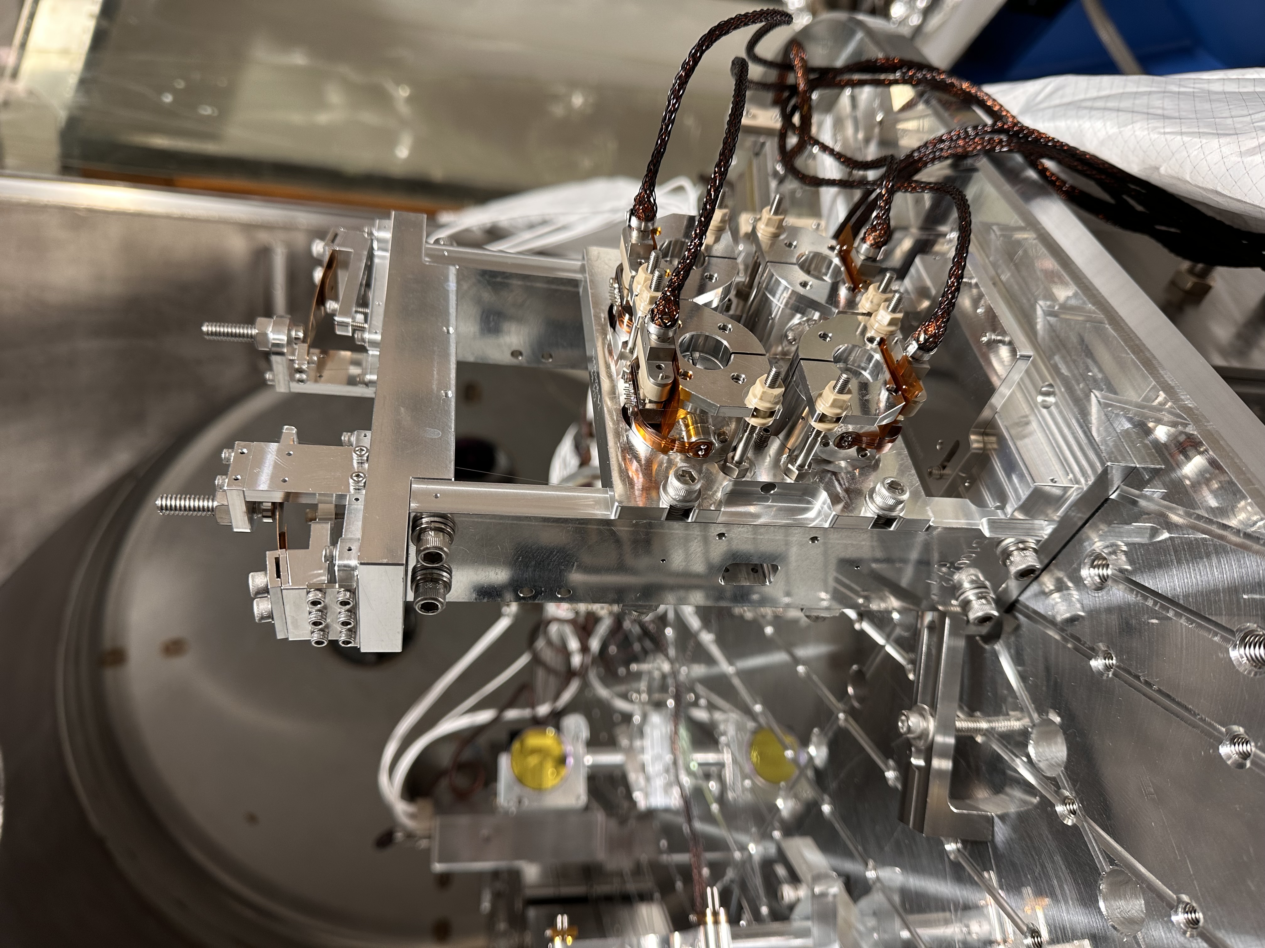
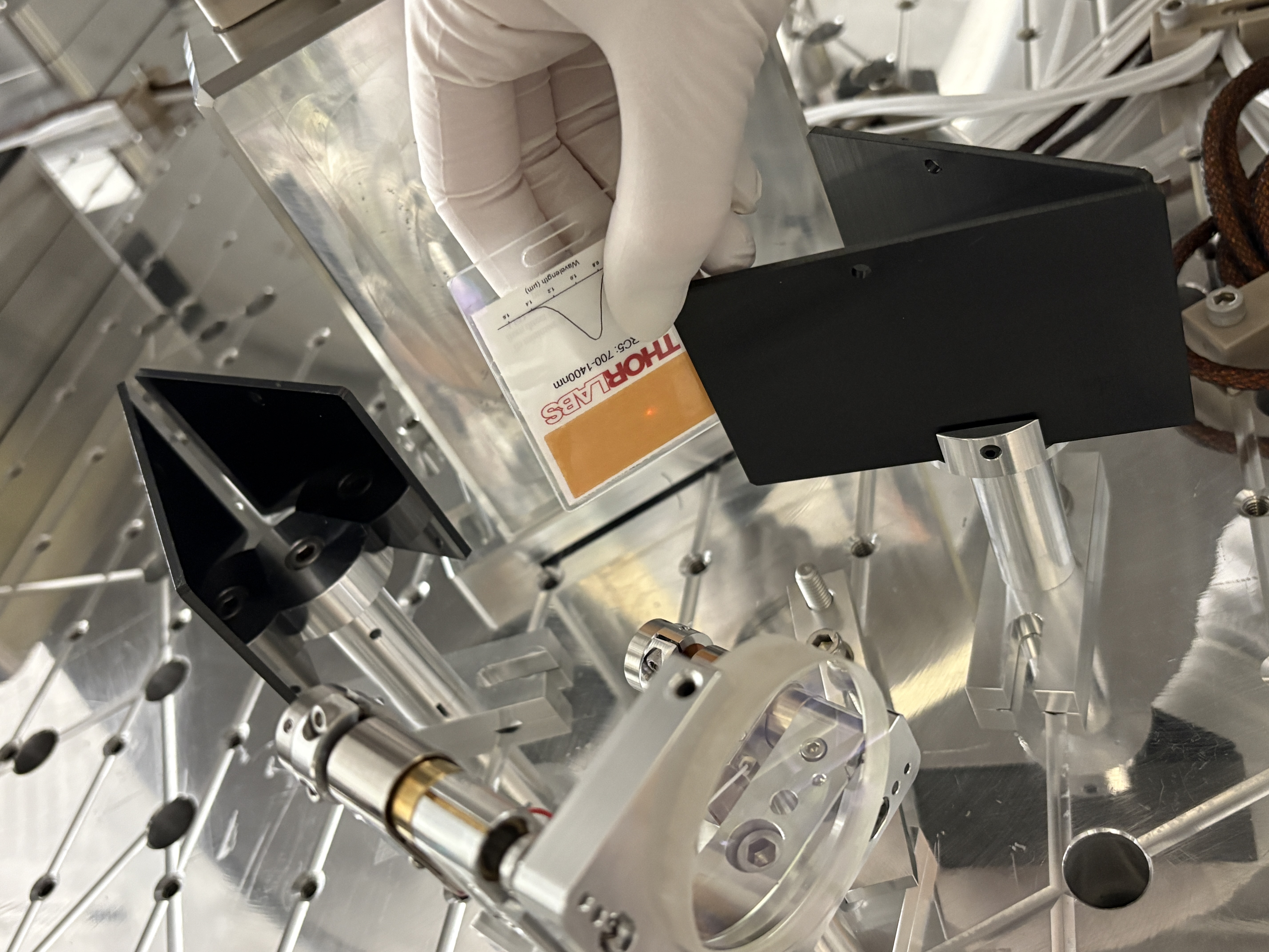
HAM1 work:
The IST1 table has been moved back into place.
GV7 has been soft closed.
Rahul took some SUS transfer functions to check for rubbing.
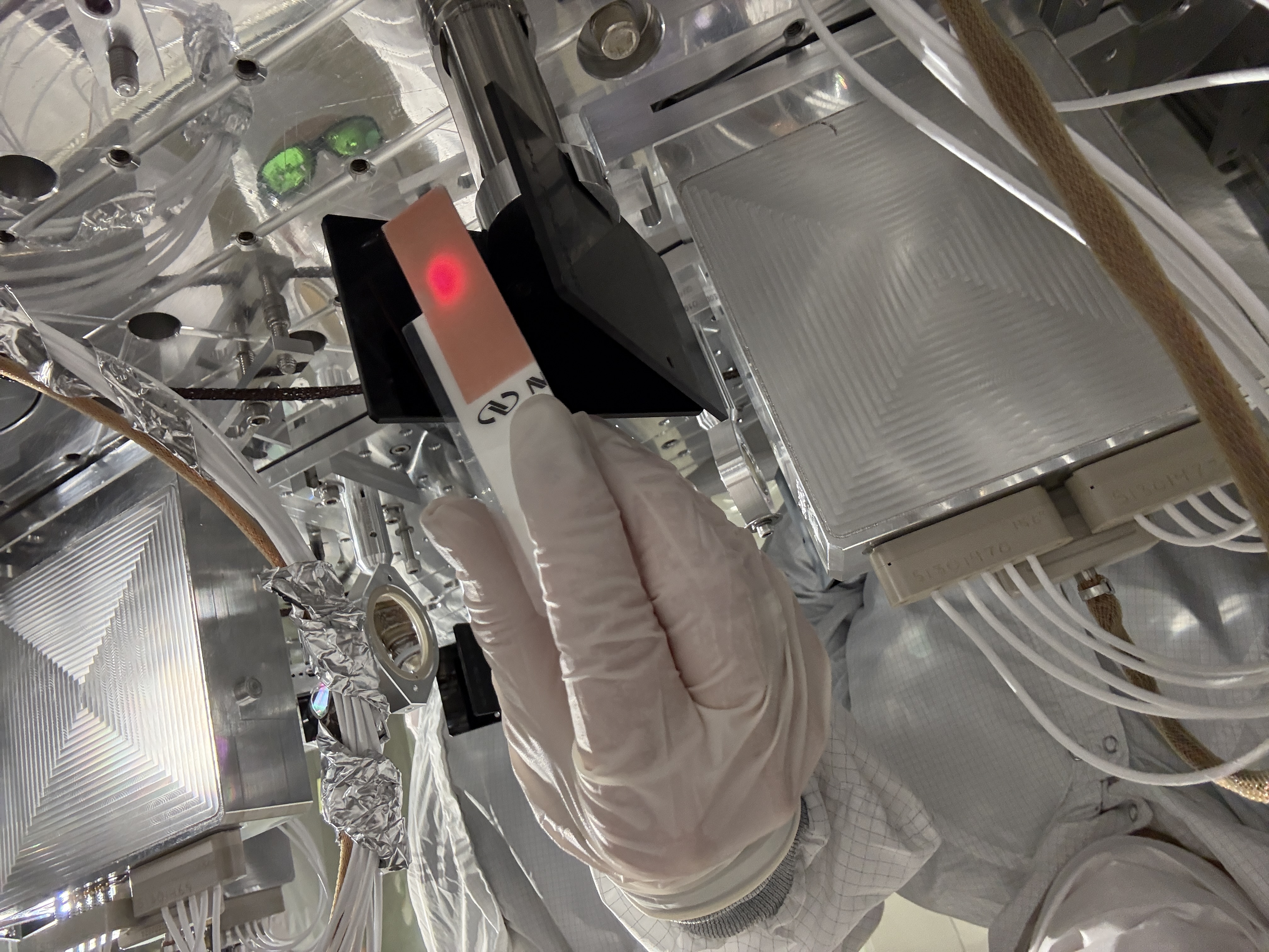
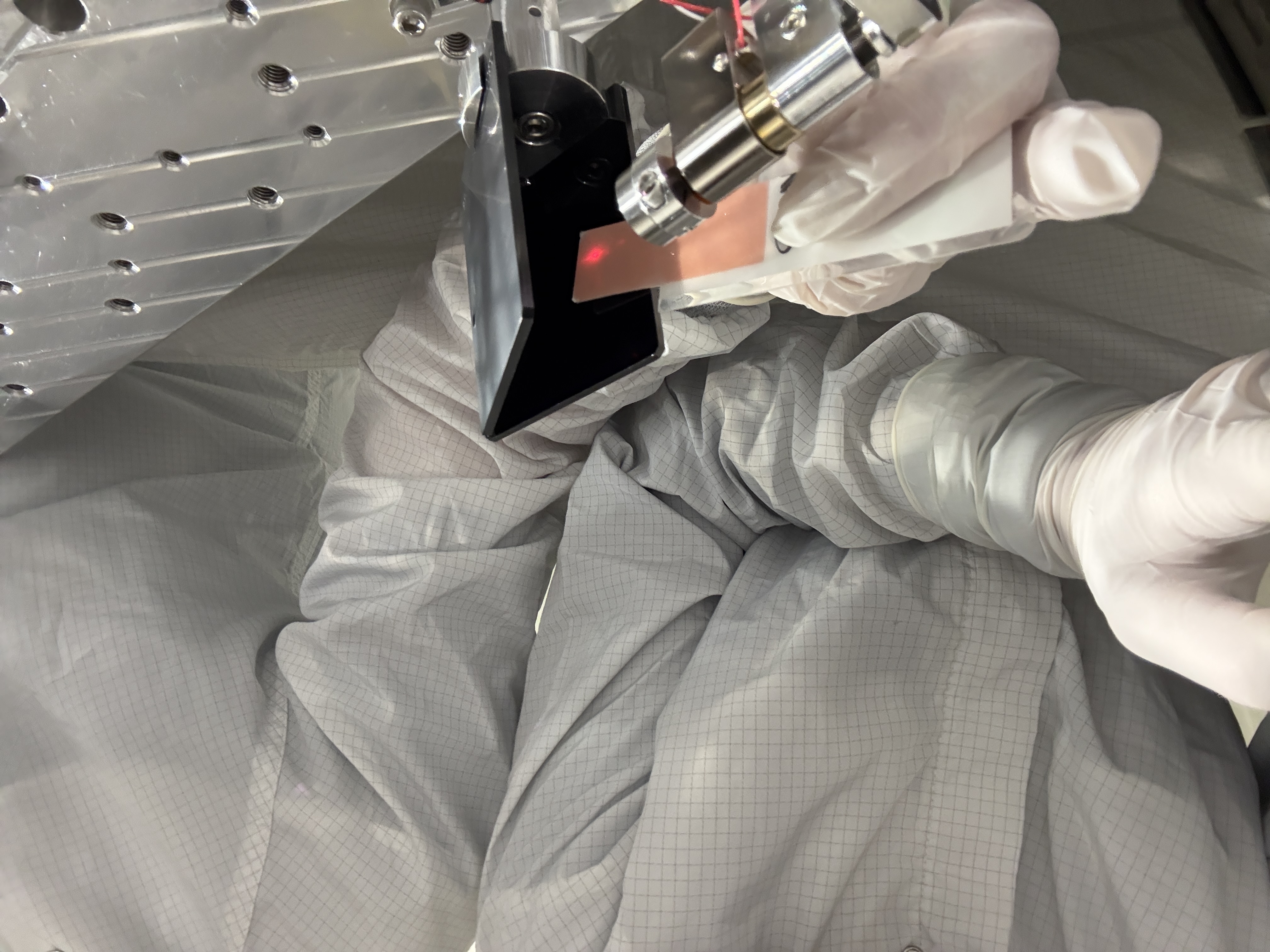
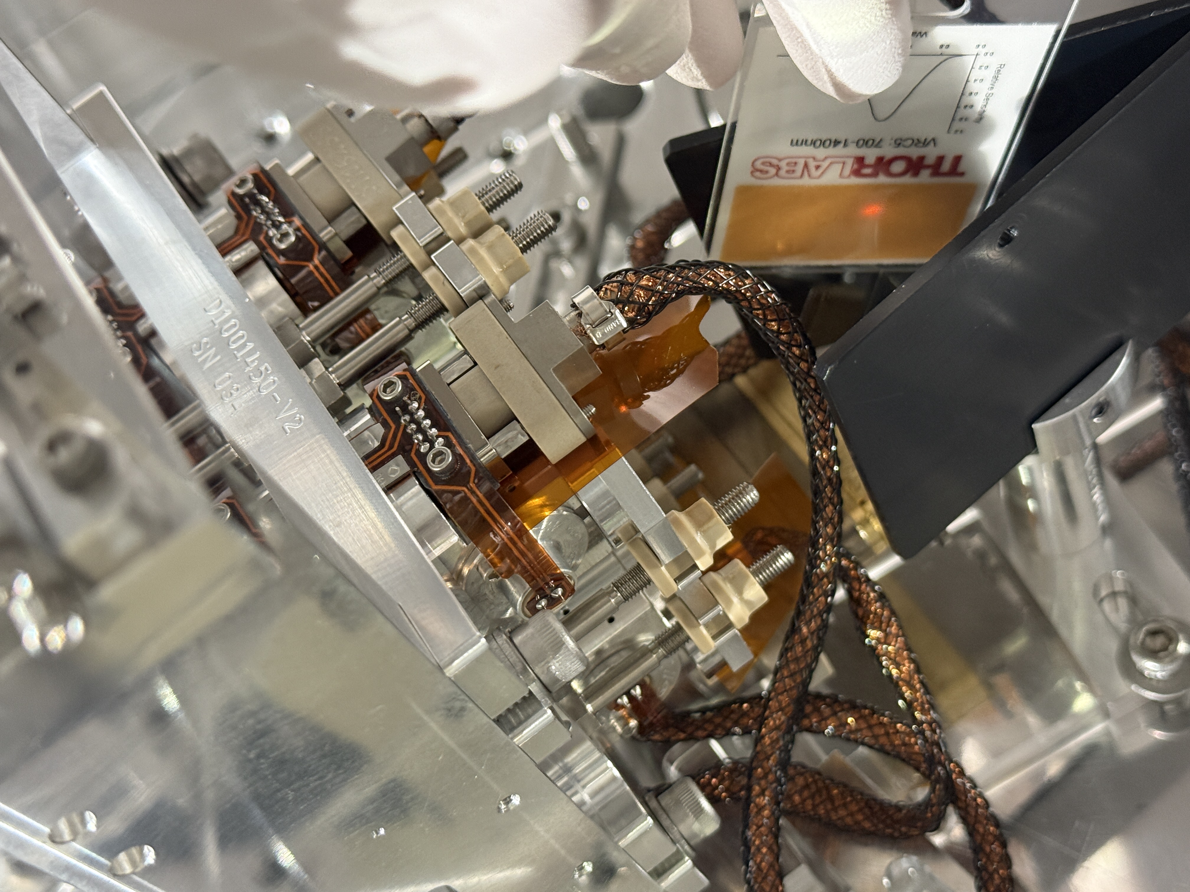
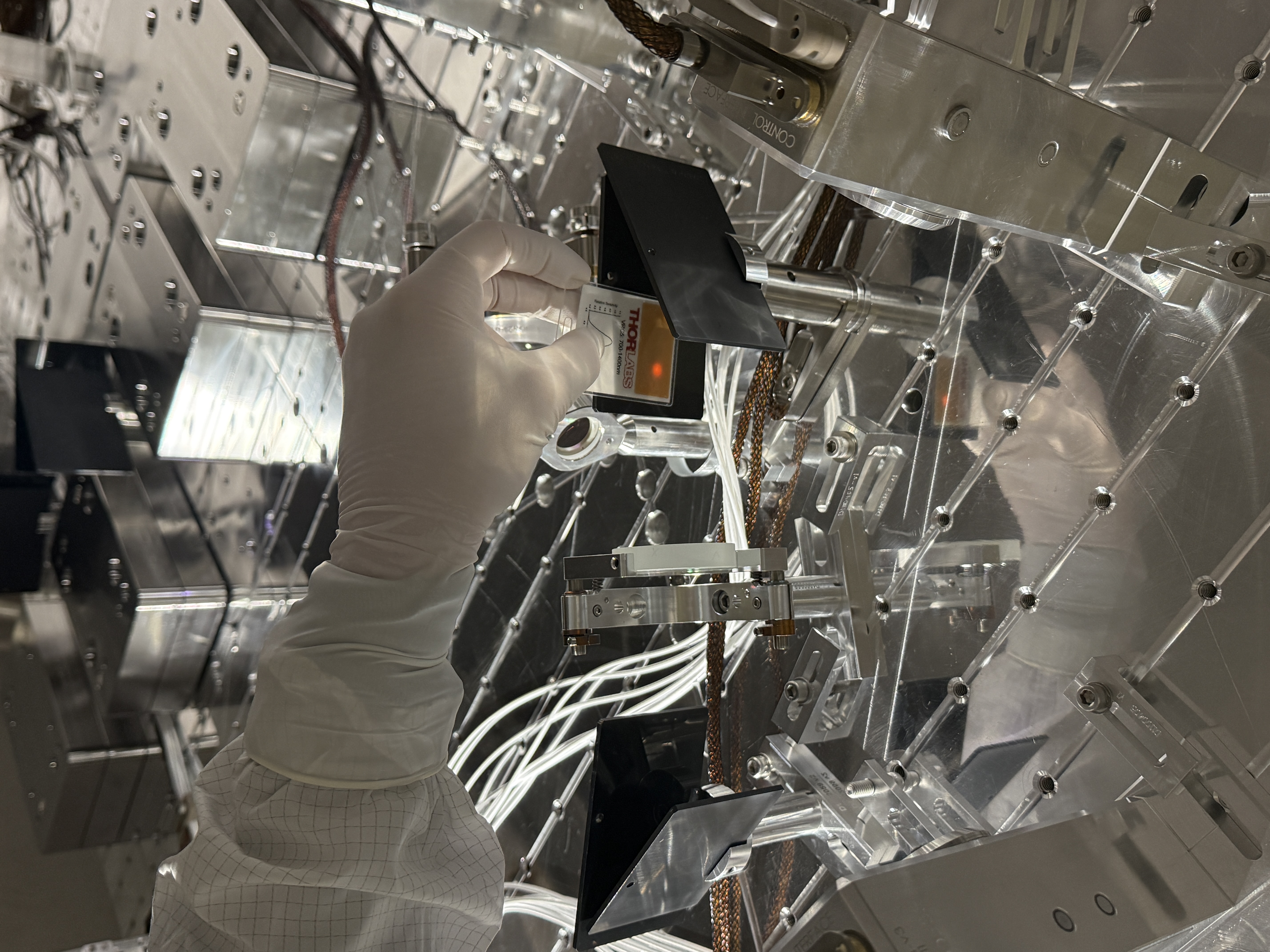
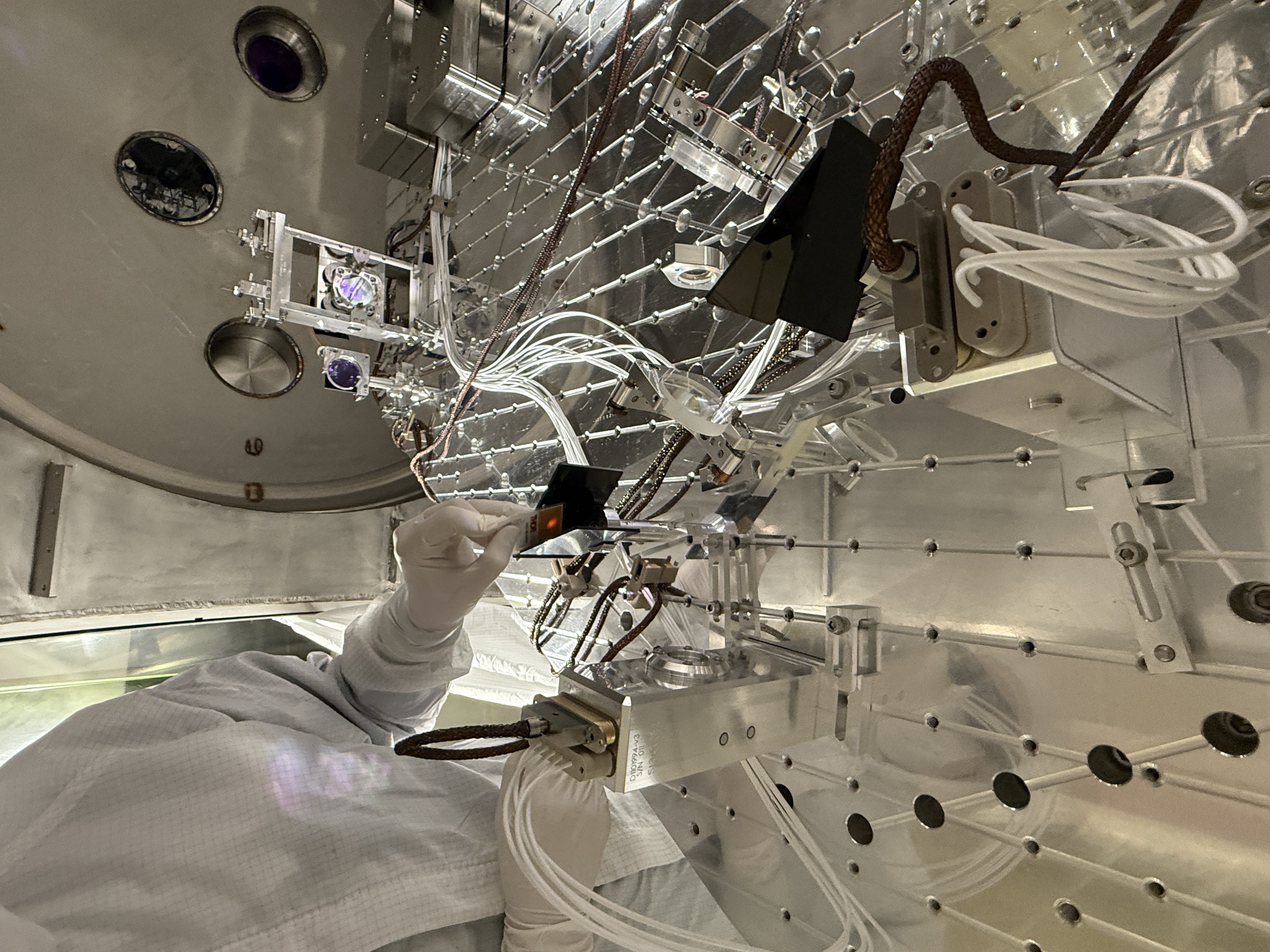
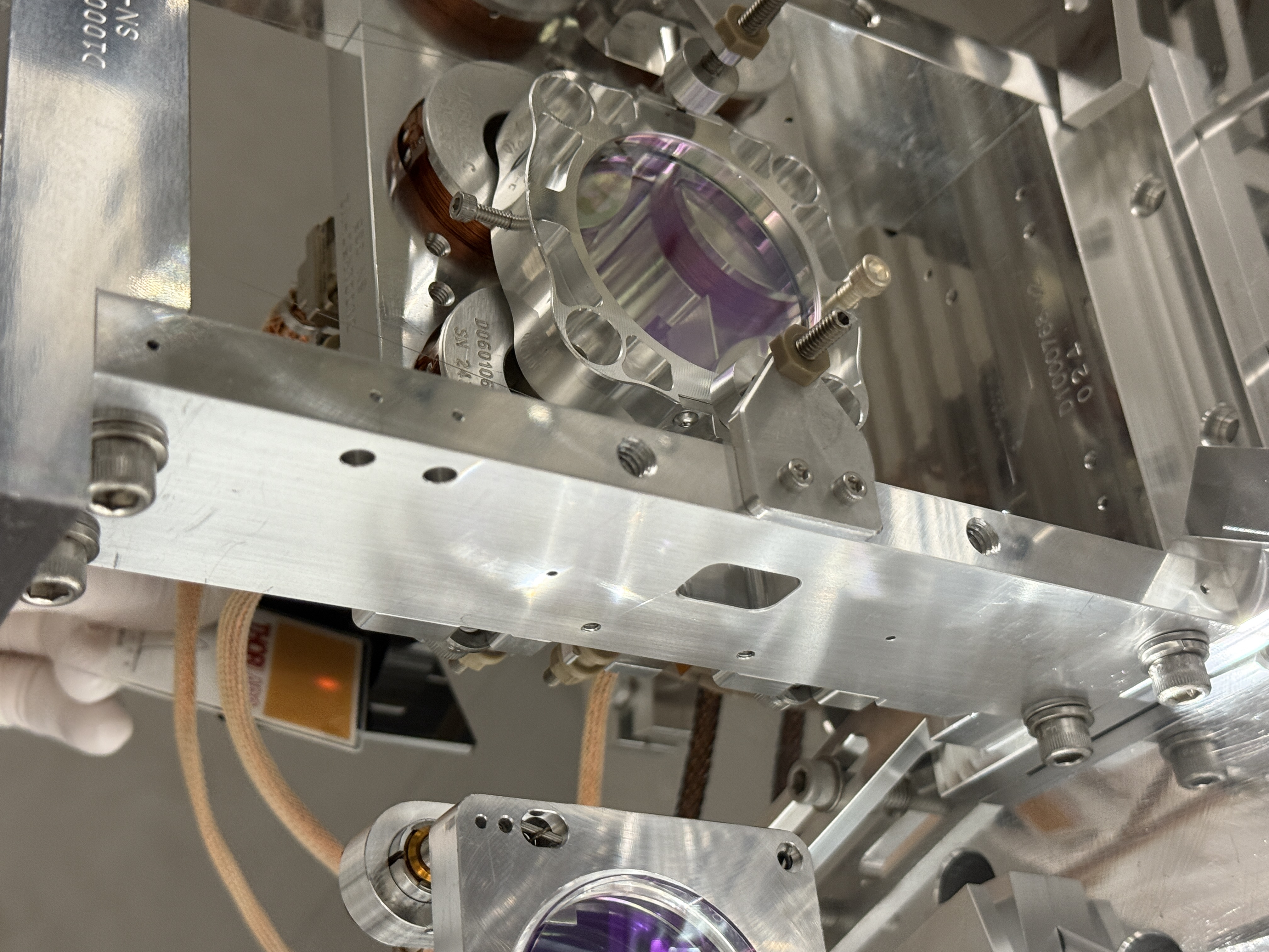
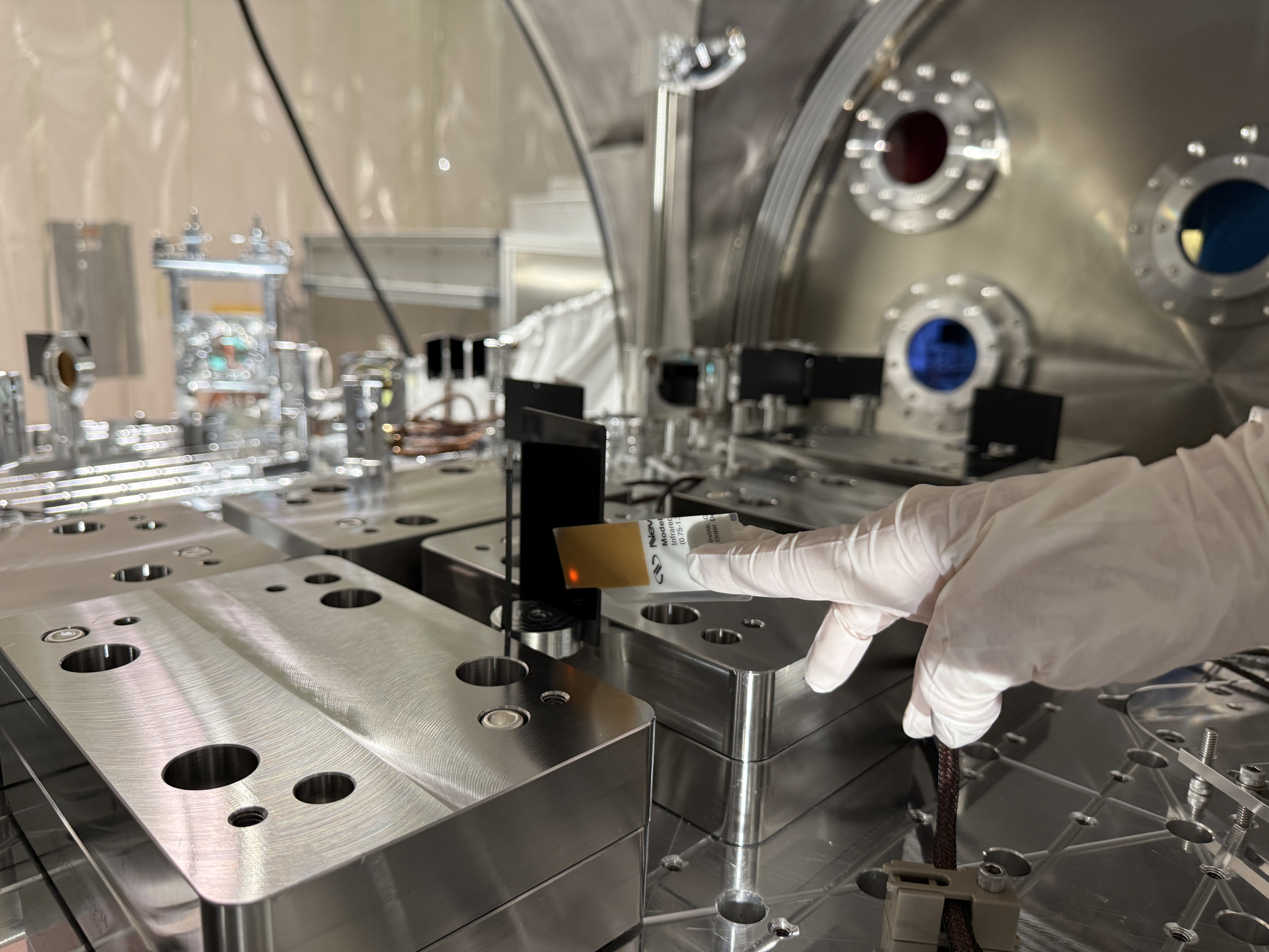
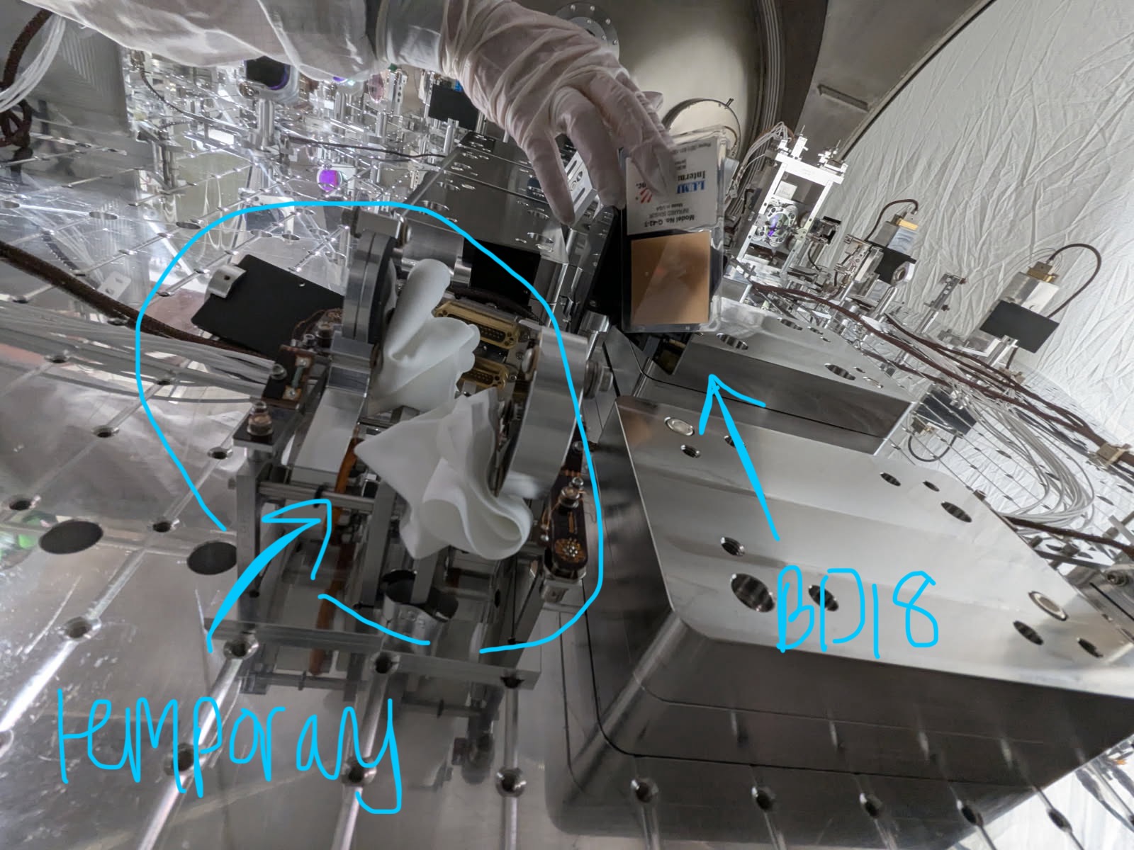
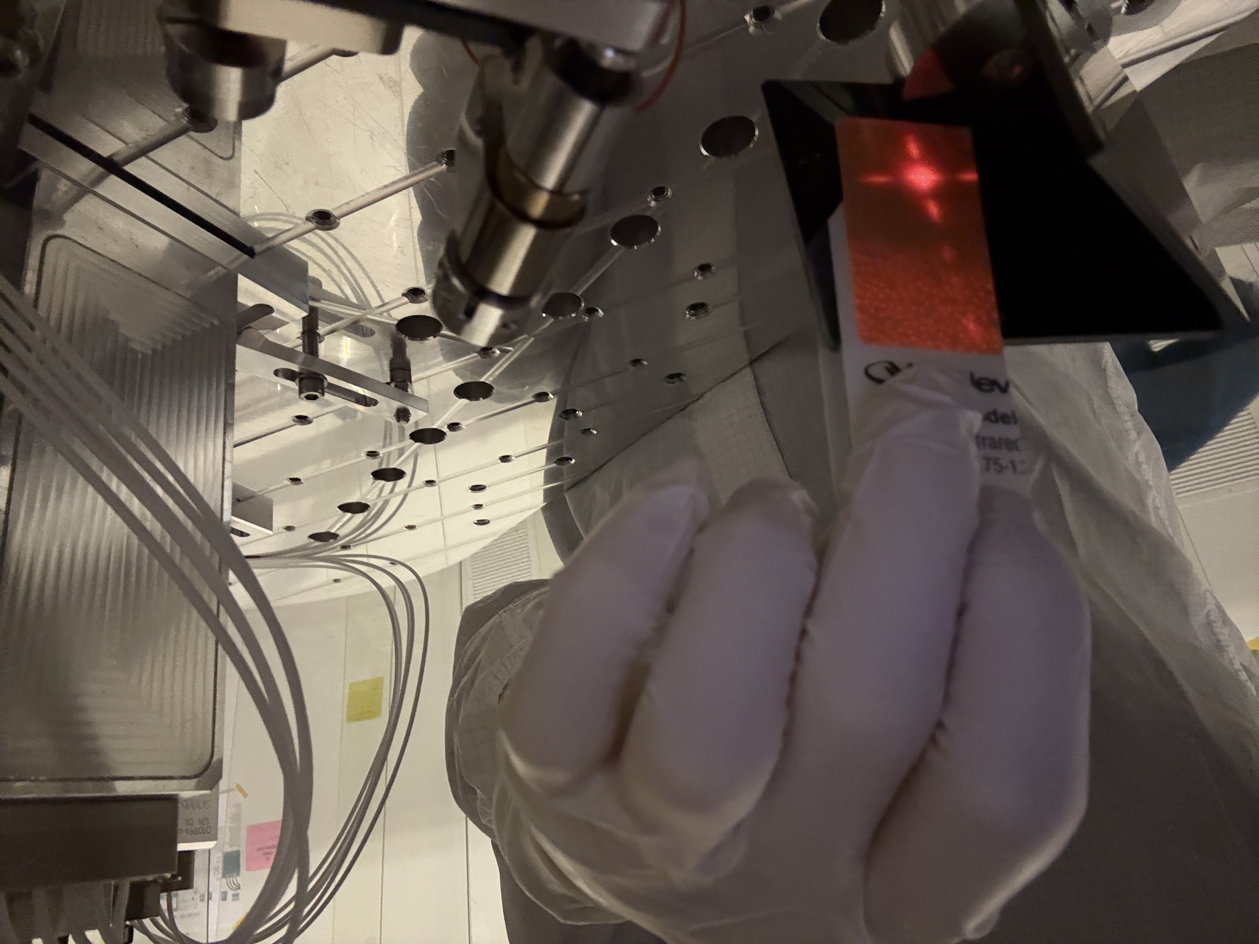
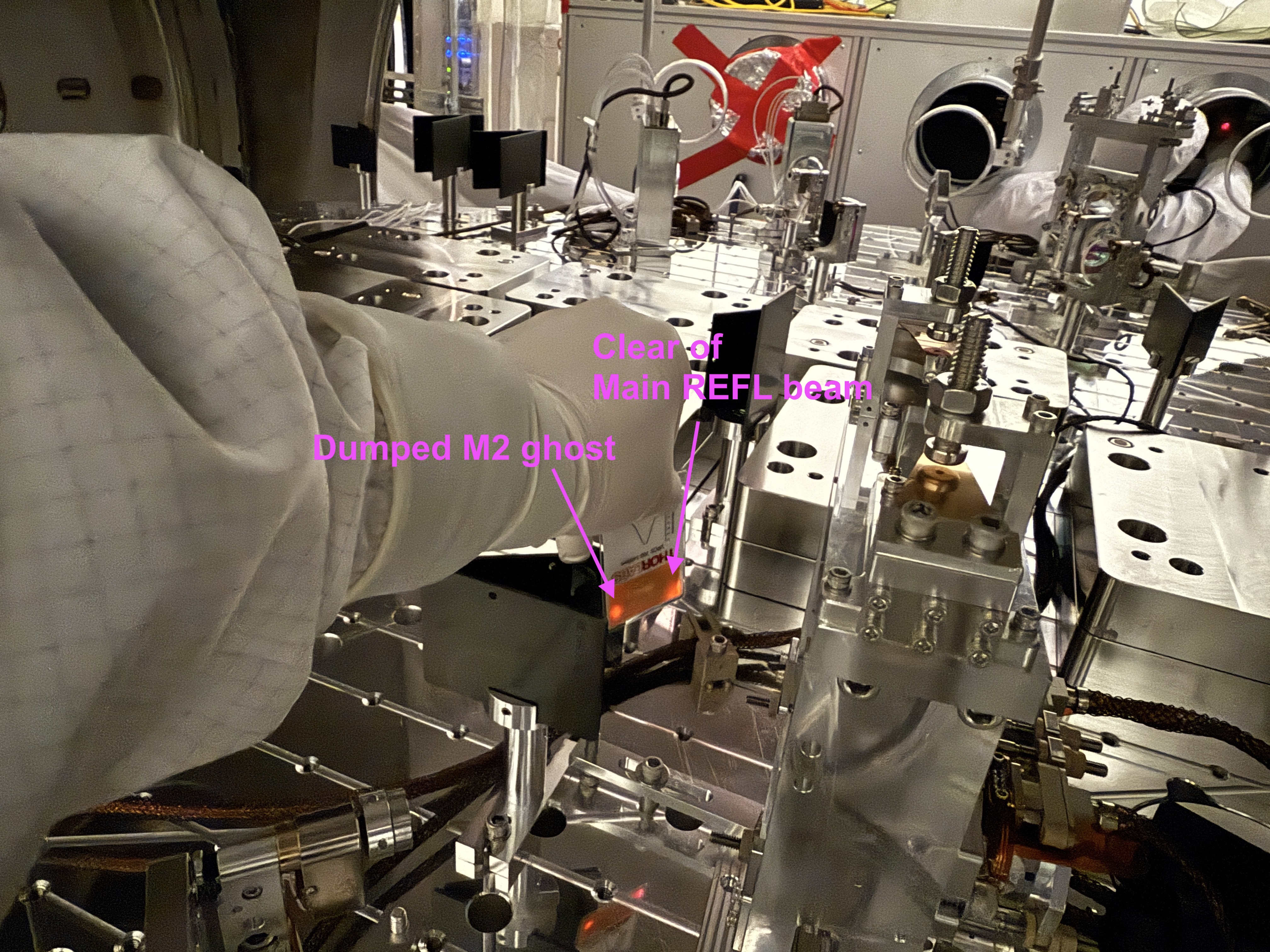
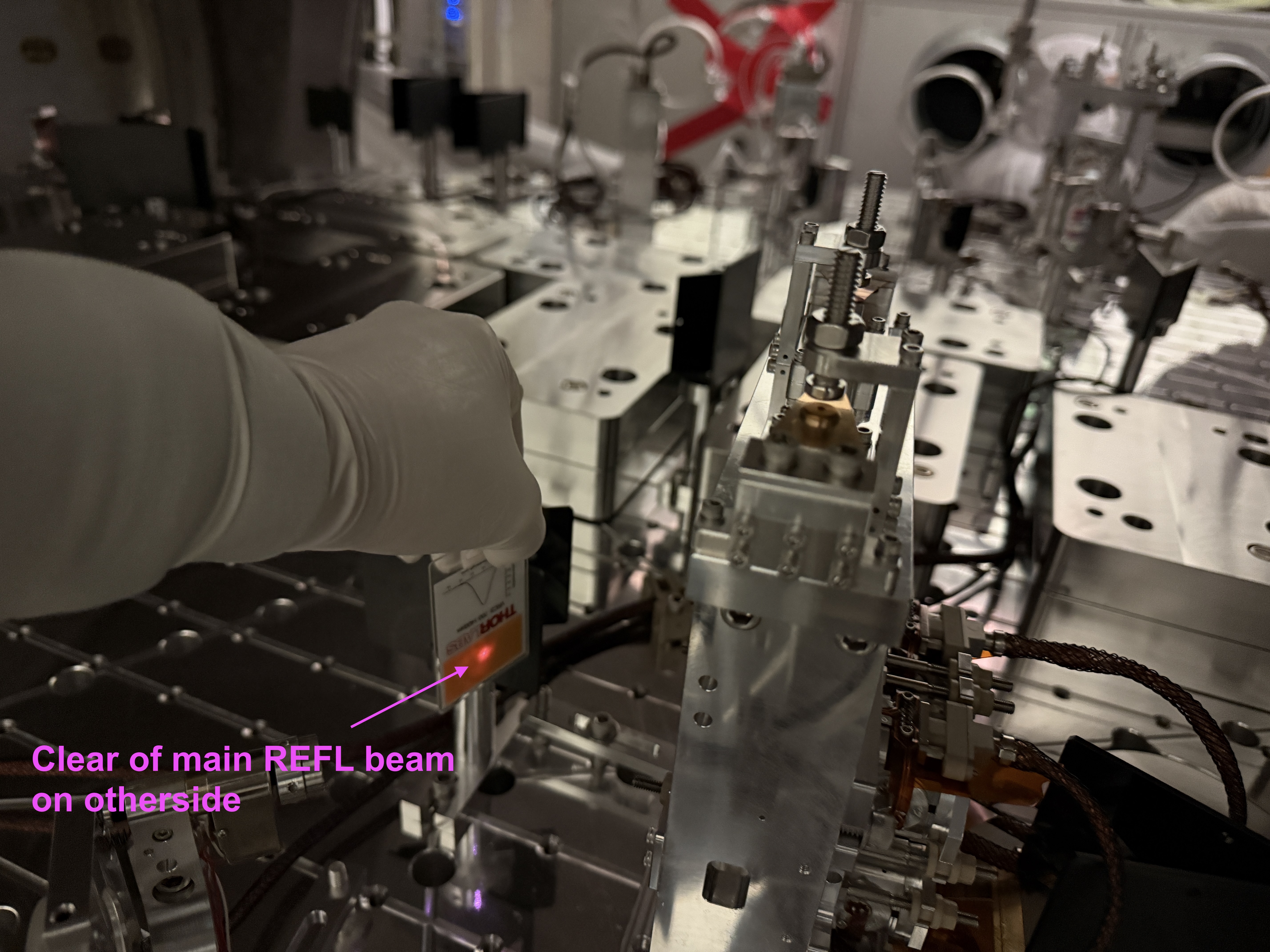
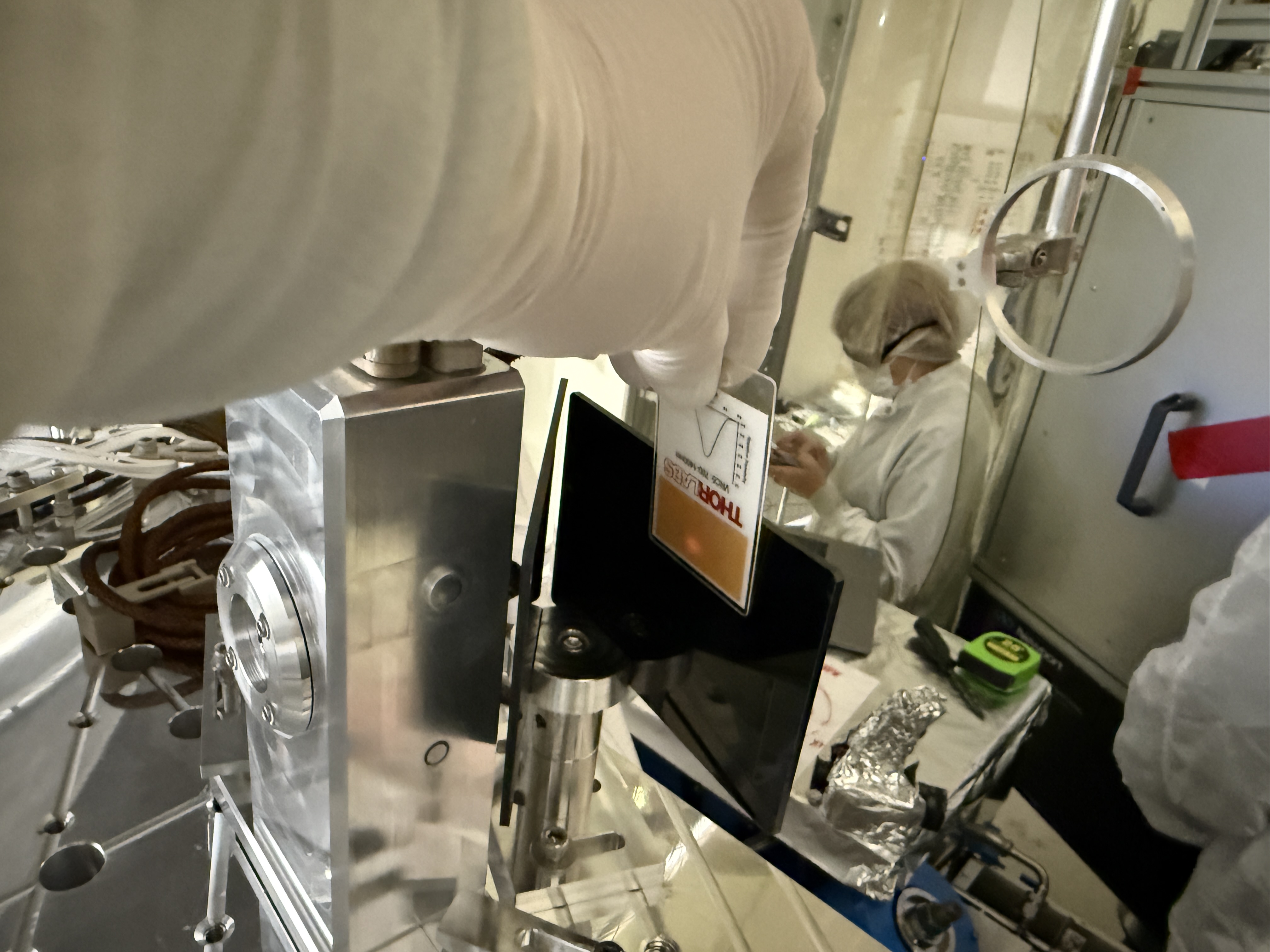
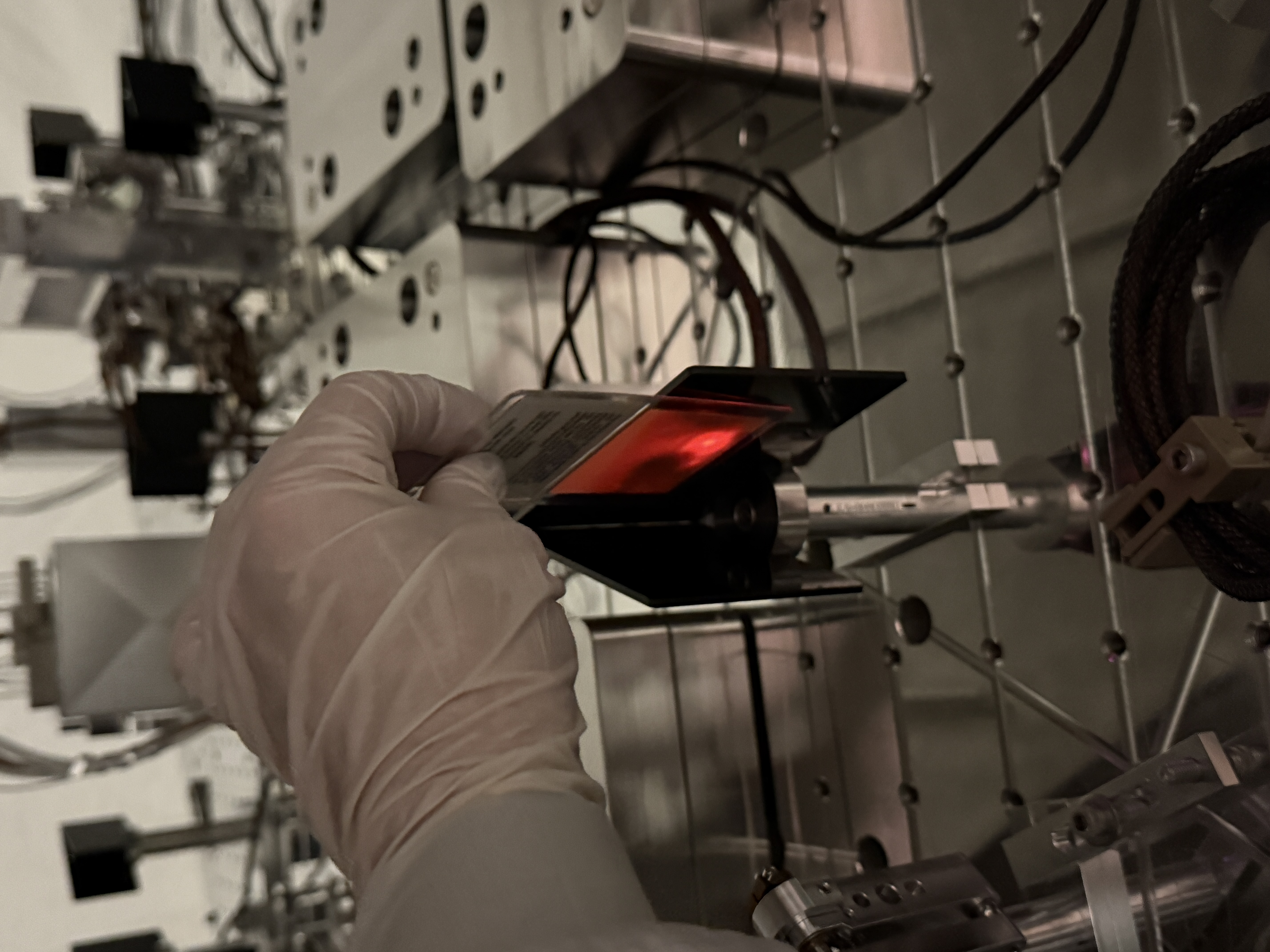
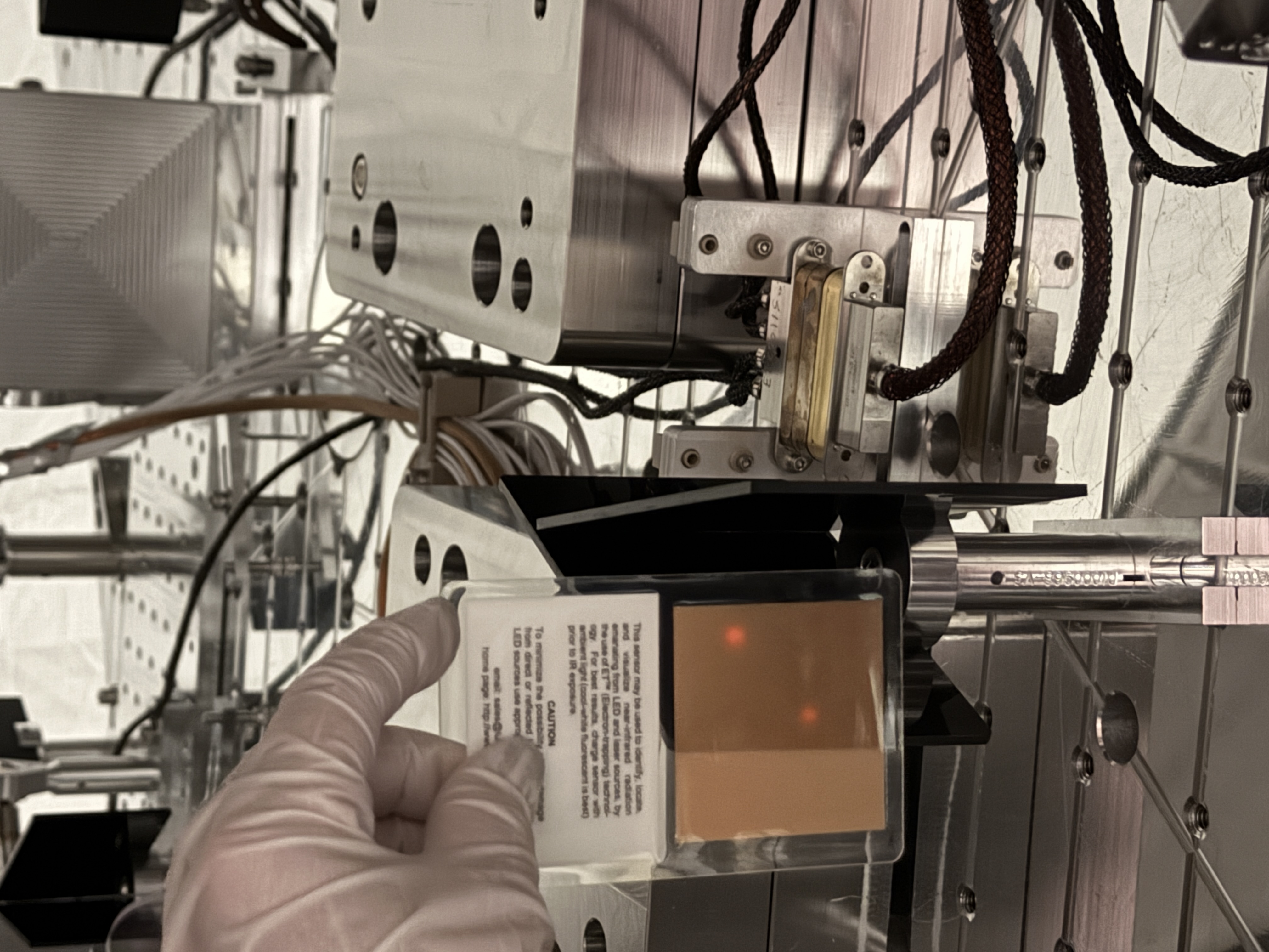
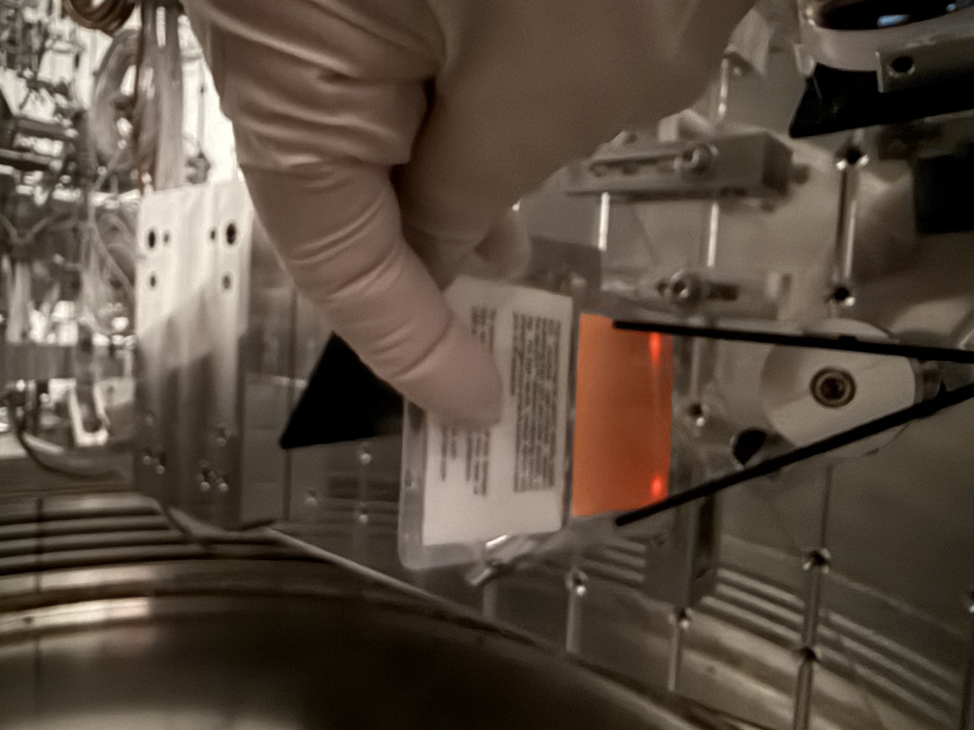
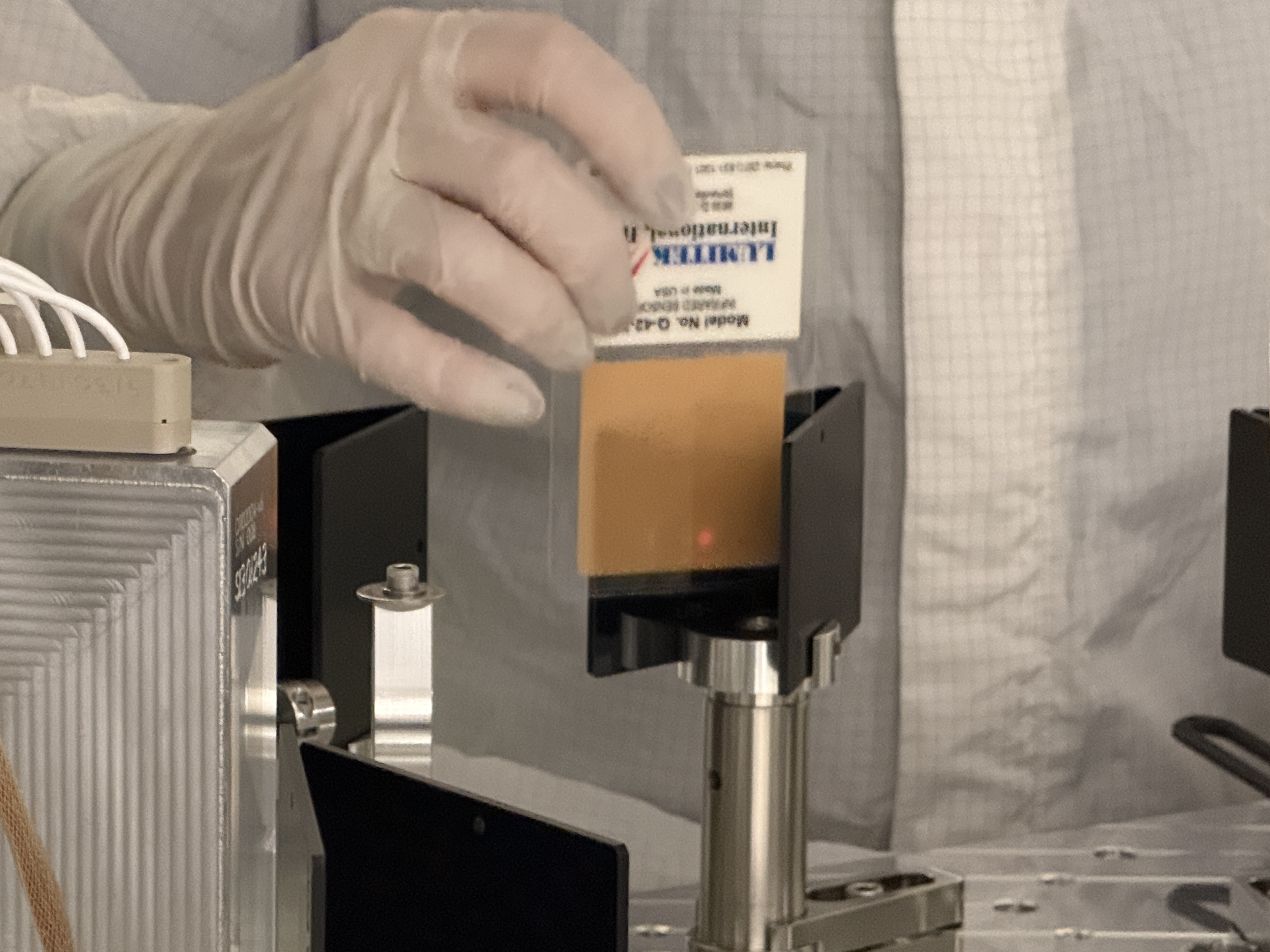
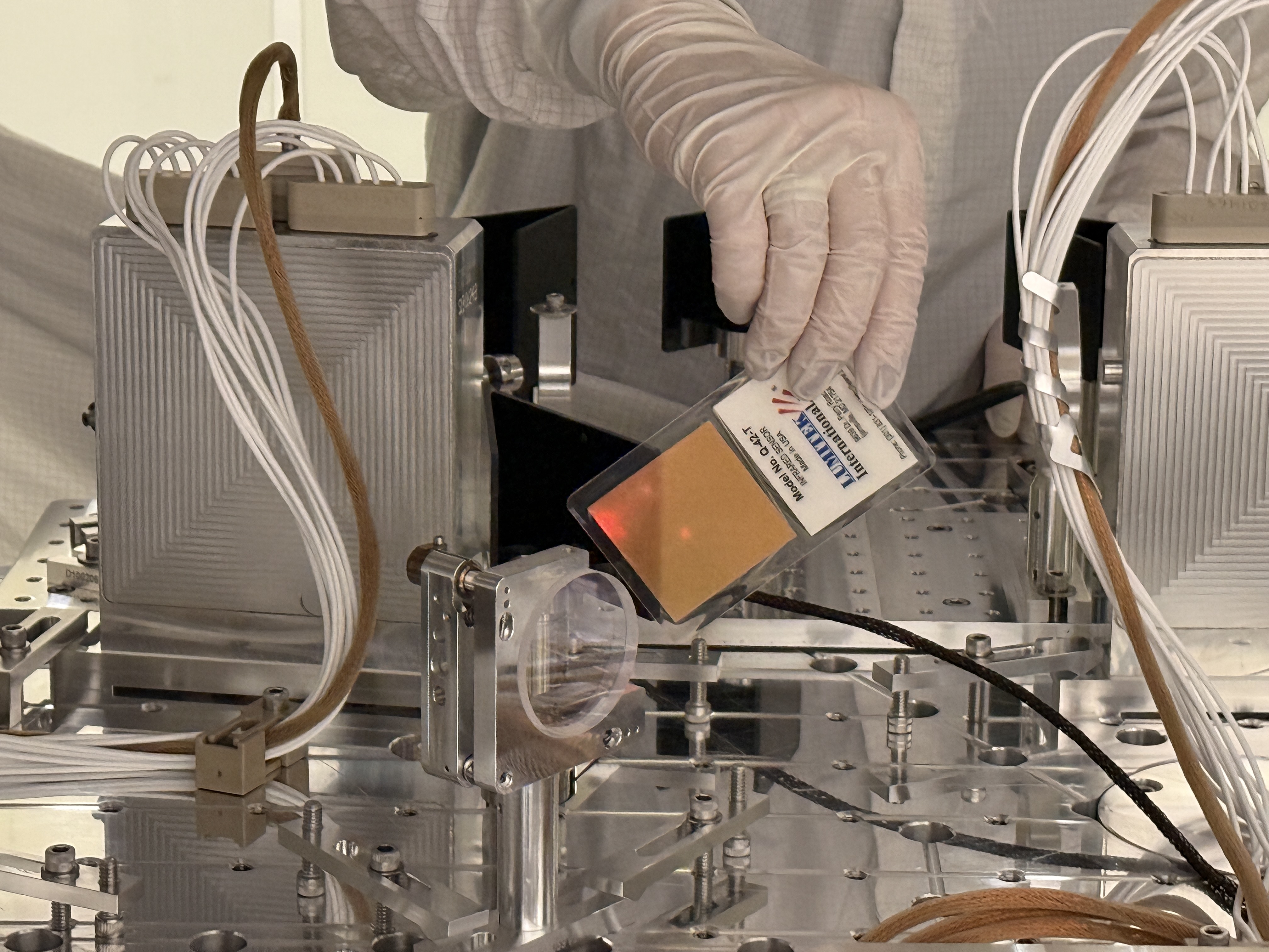
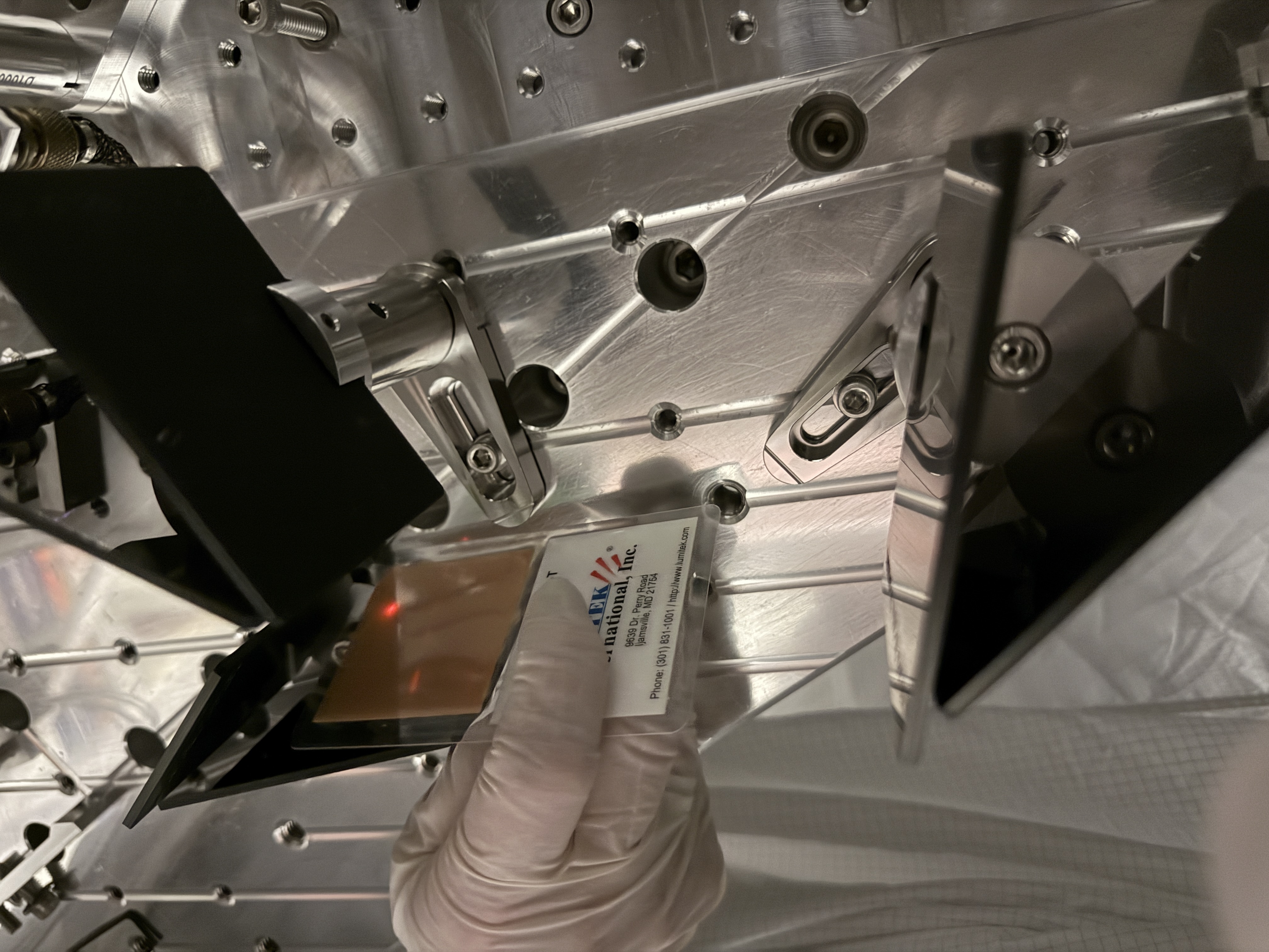
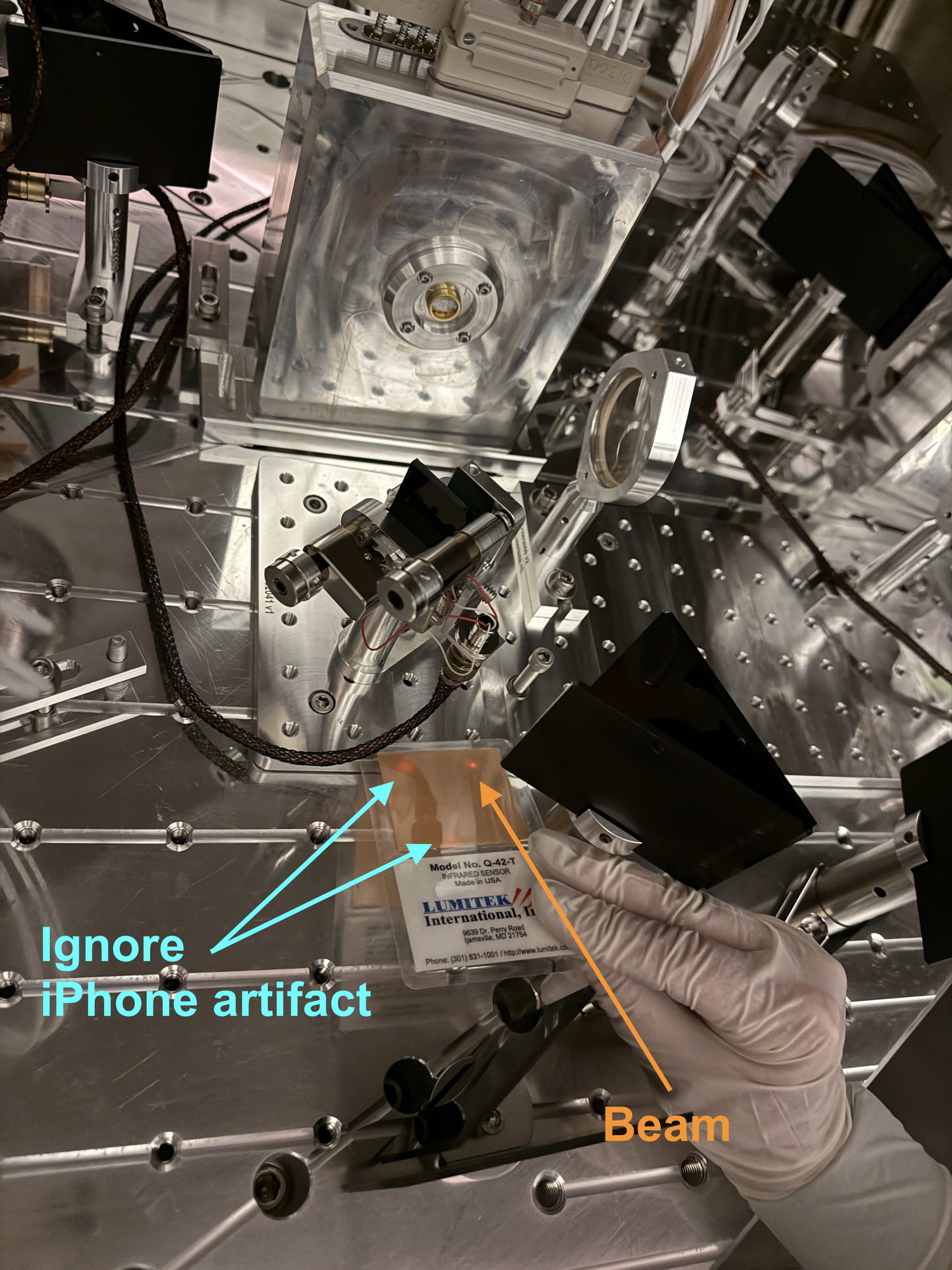
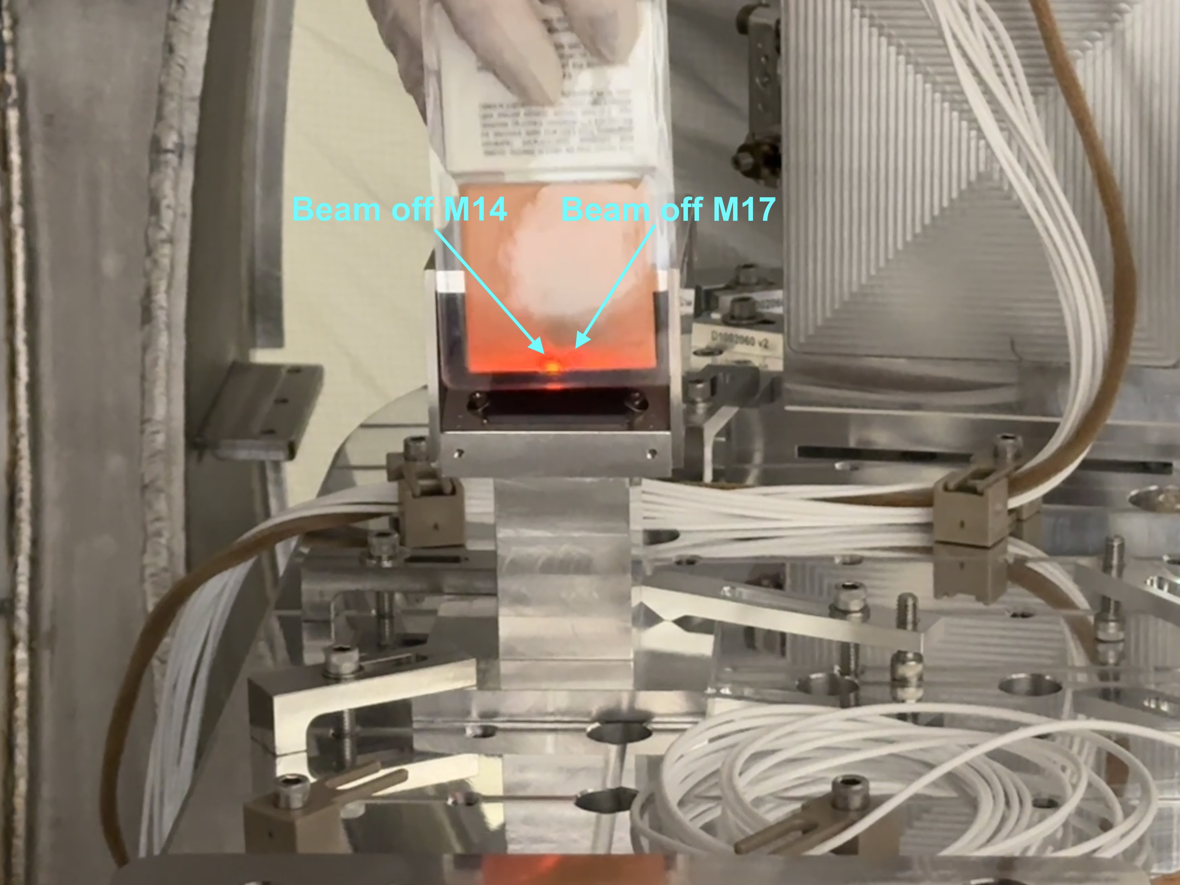
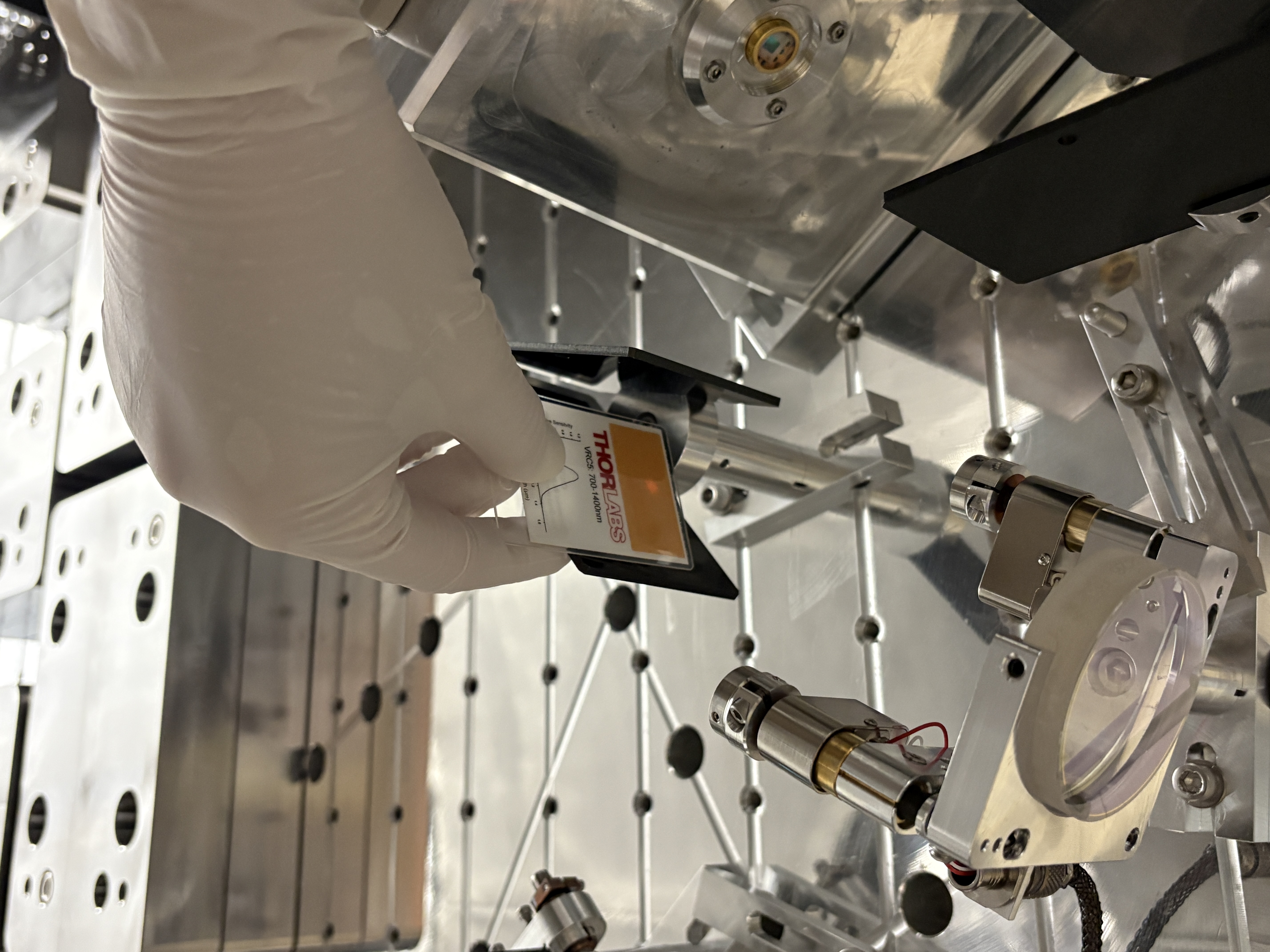
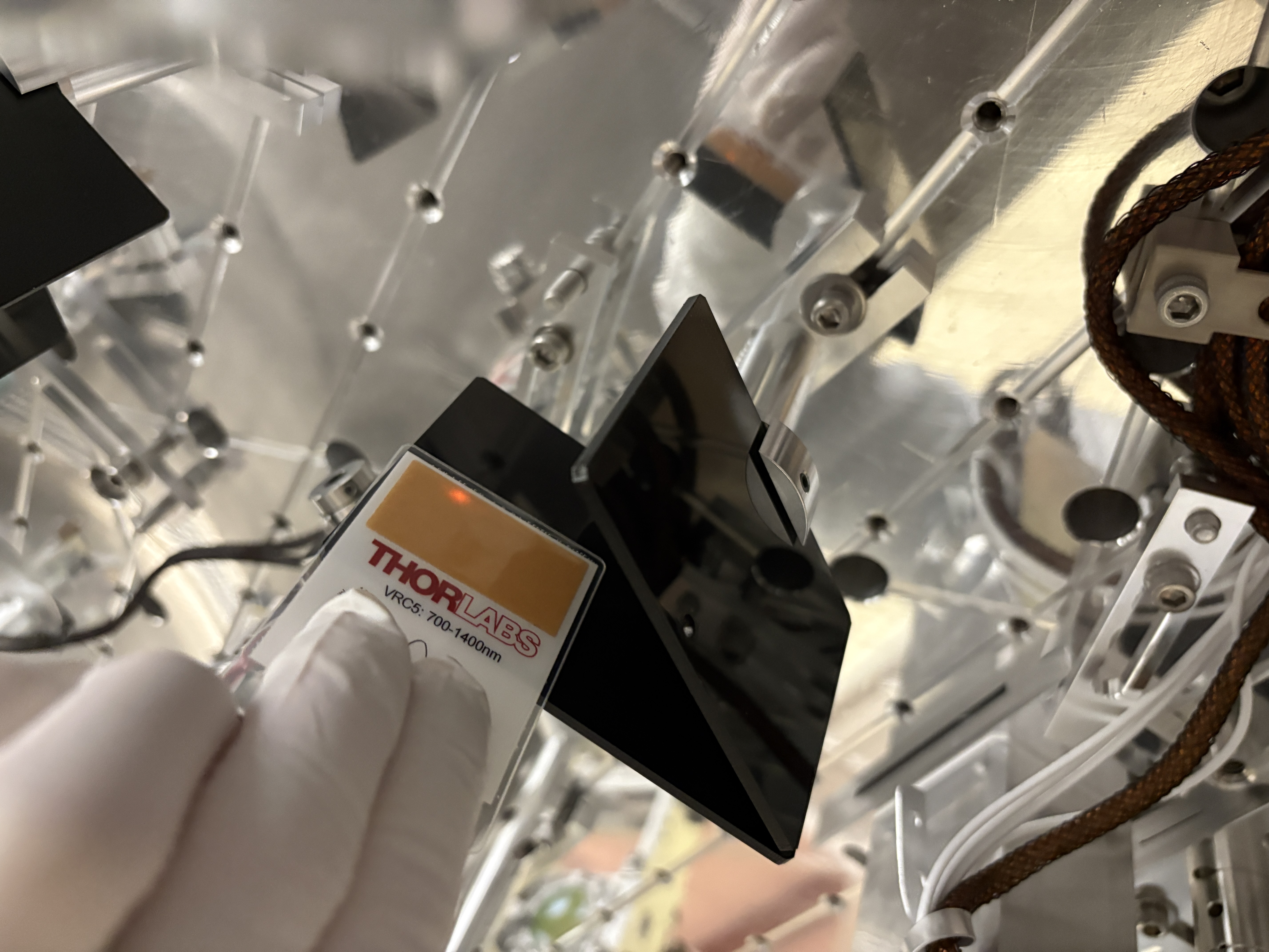
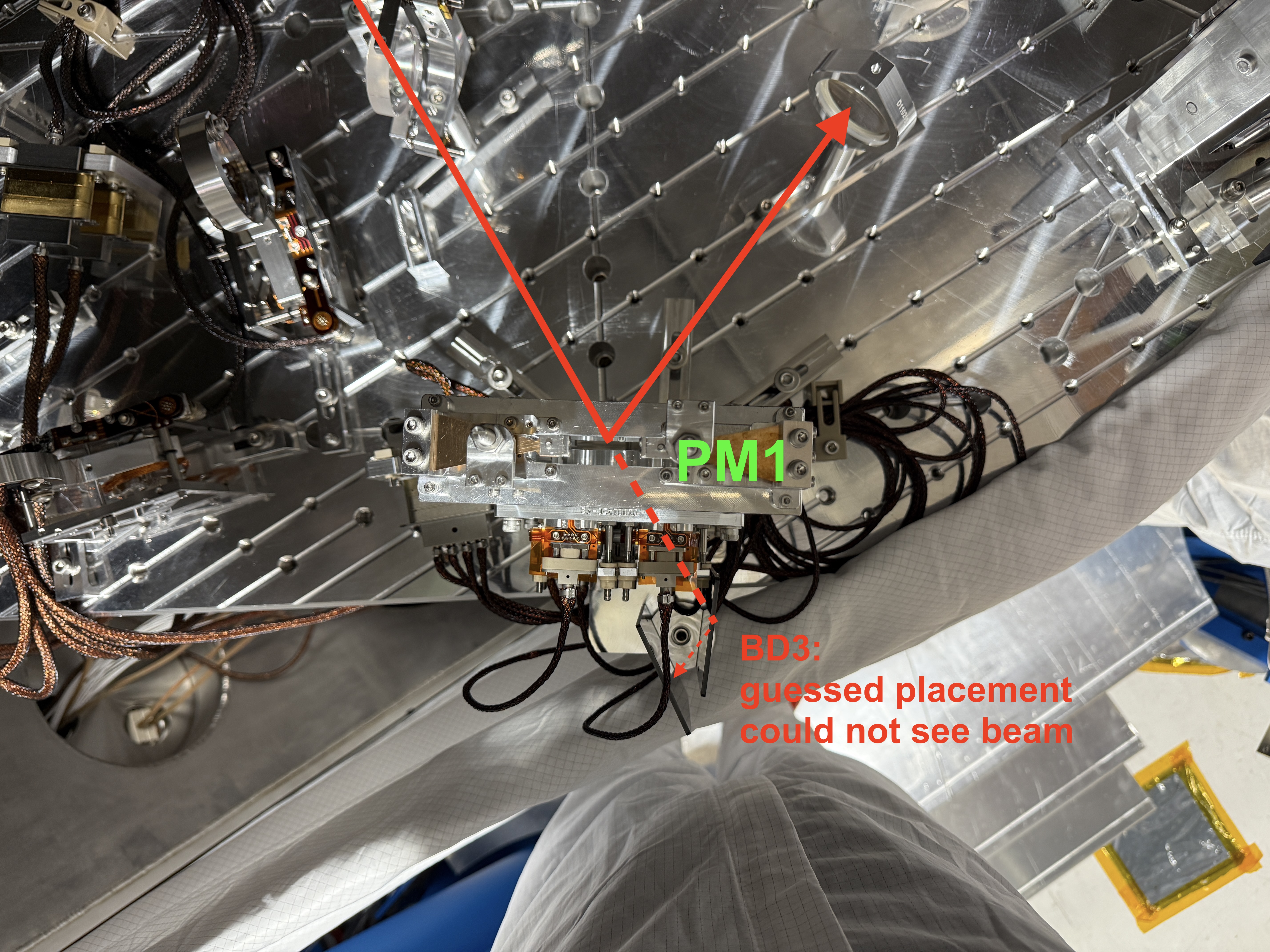
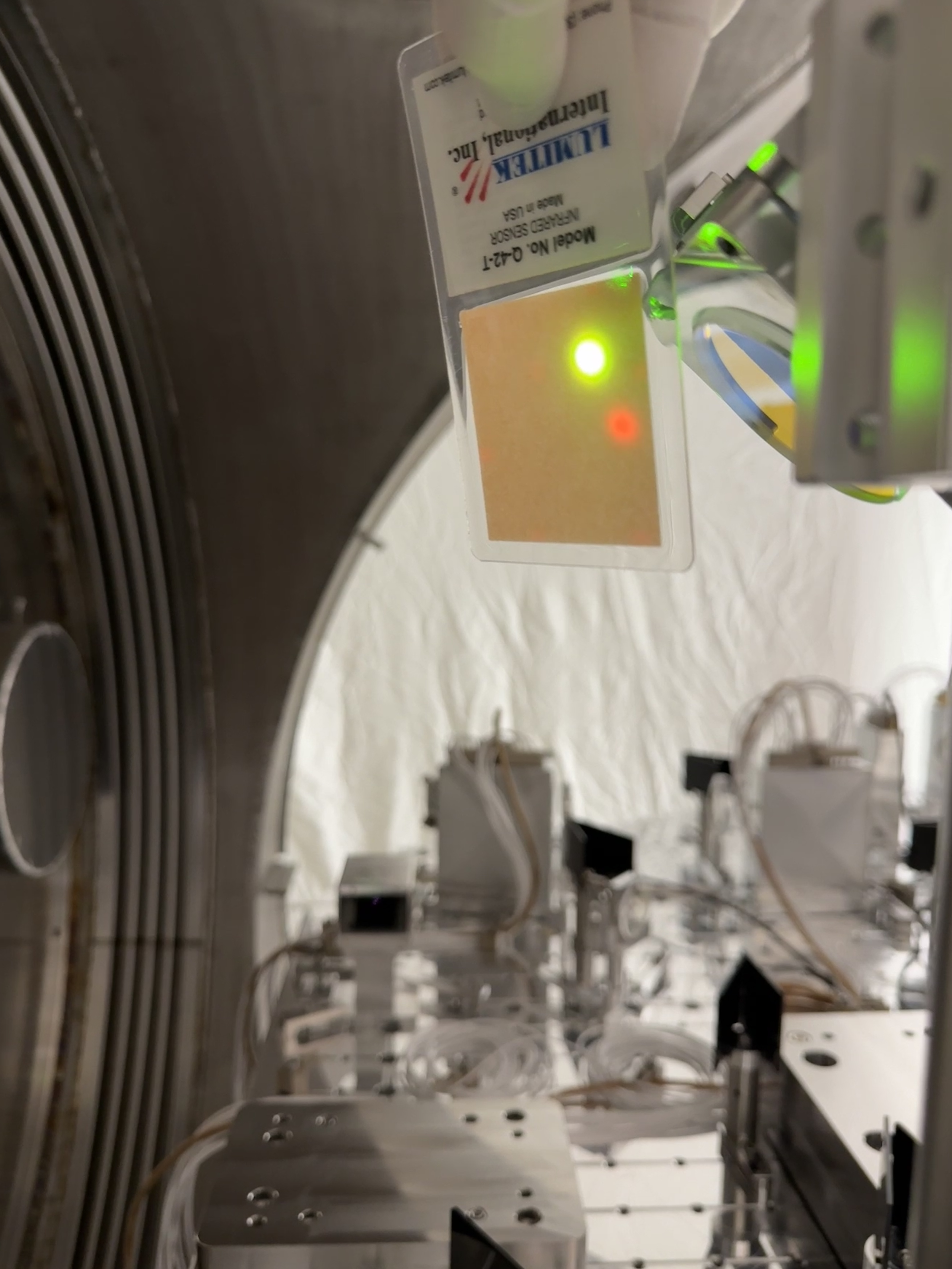
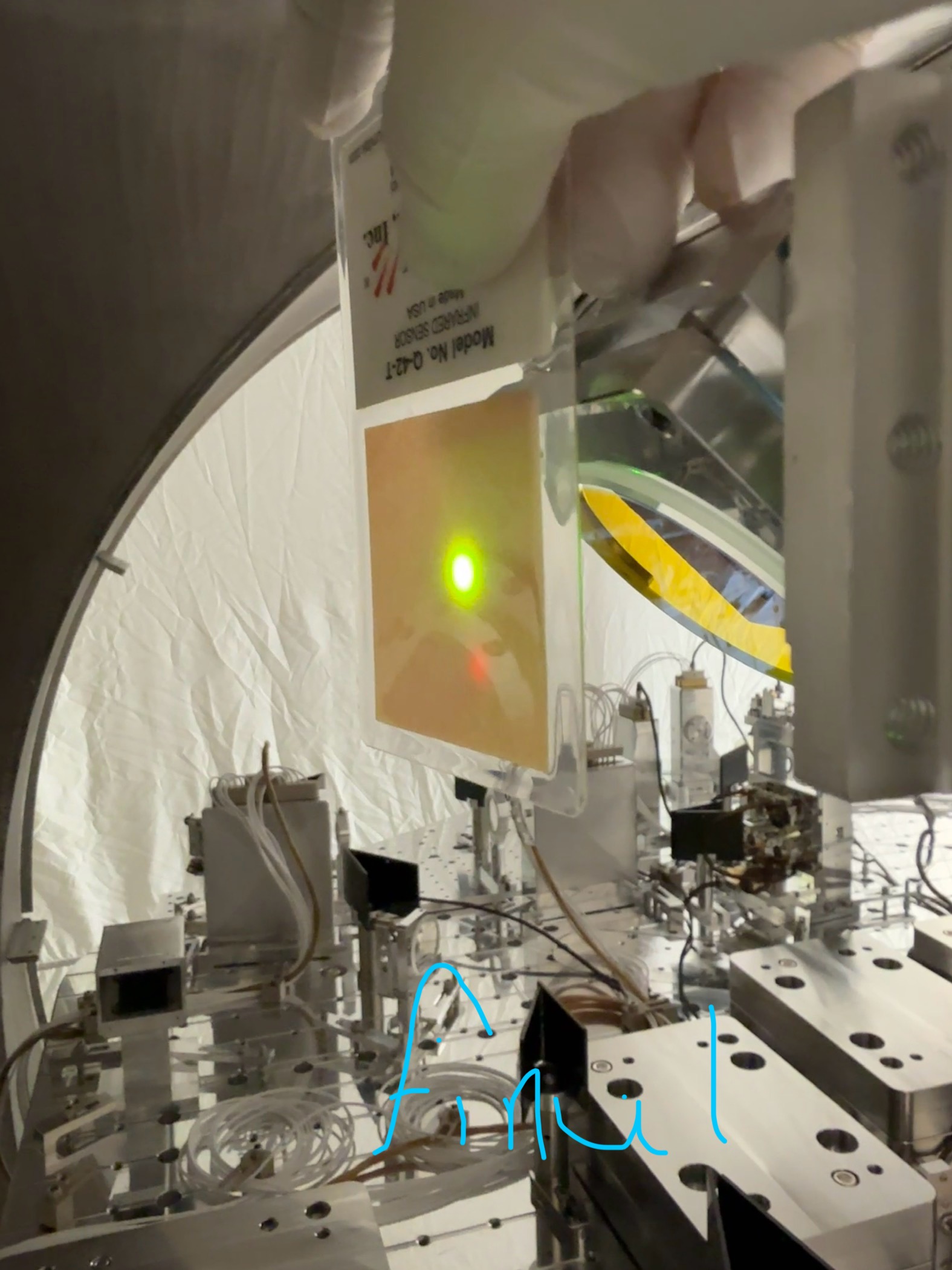
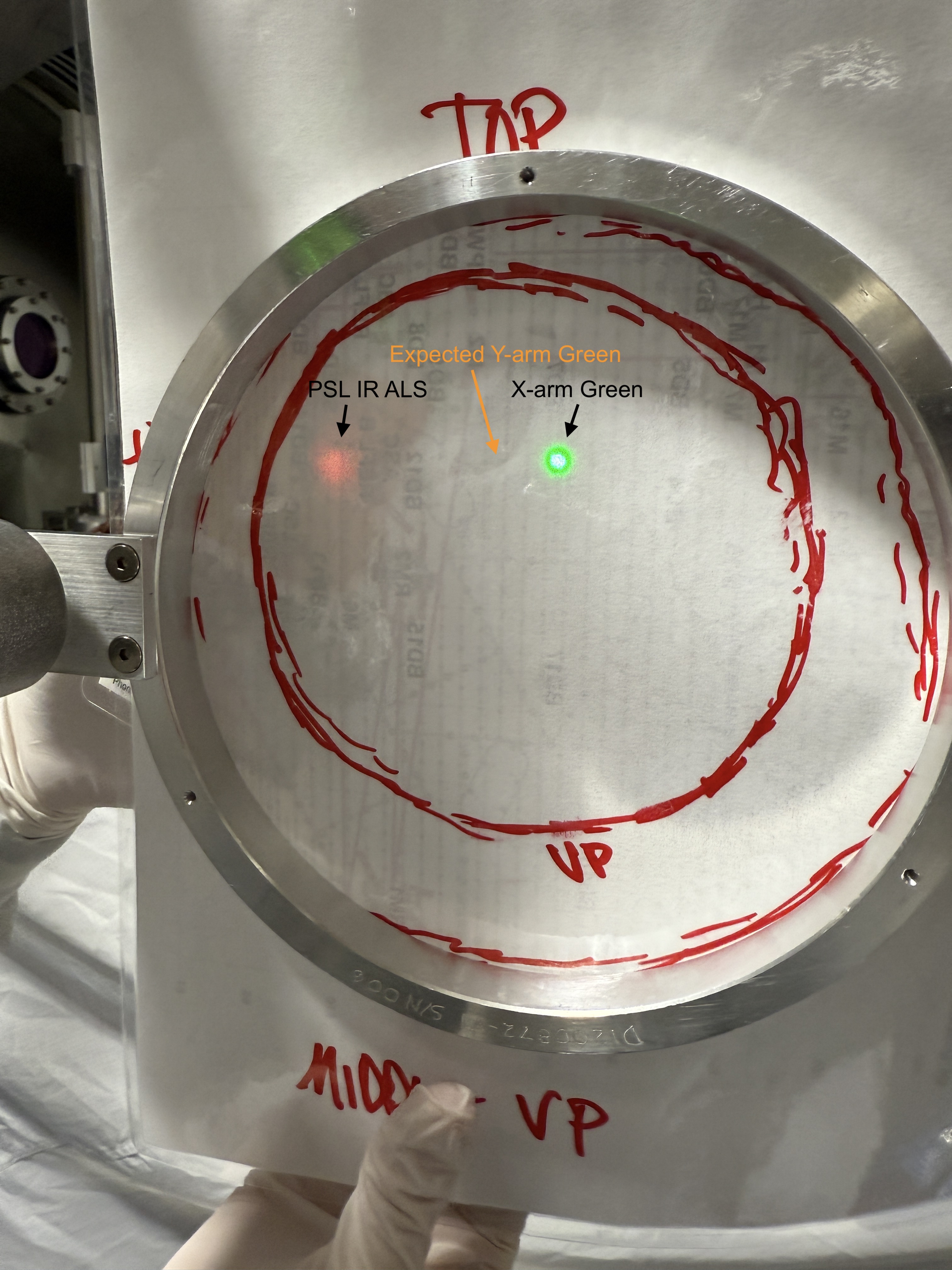
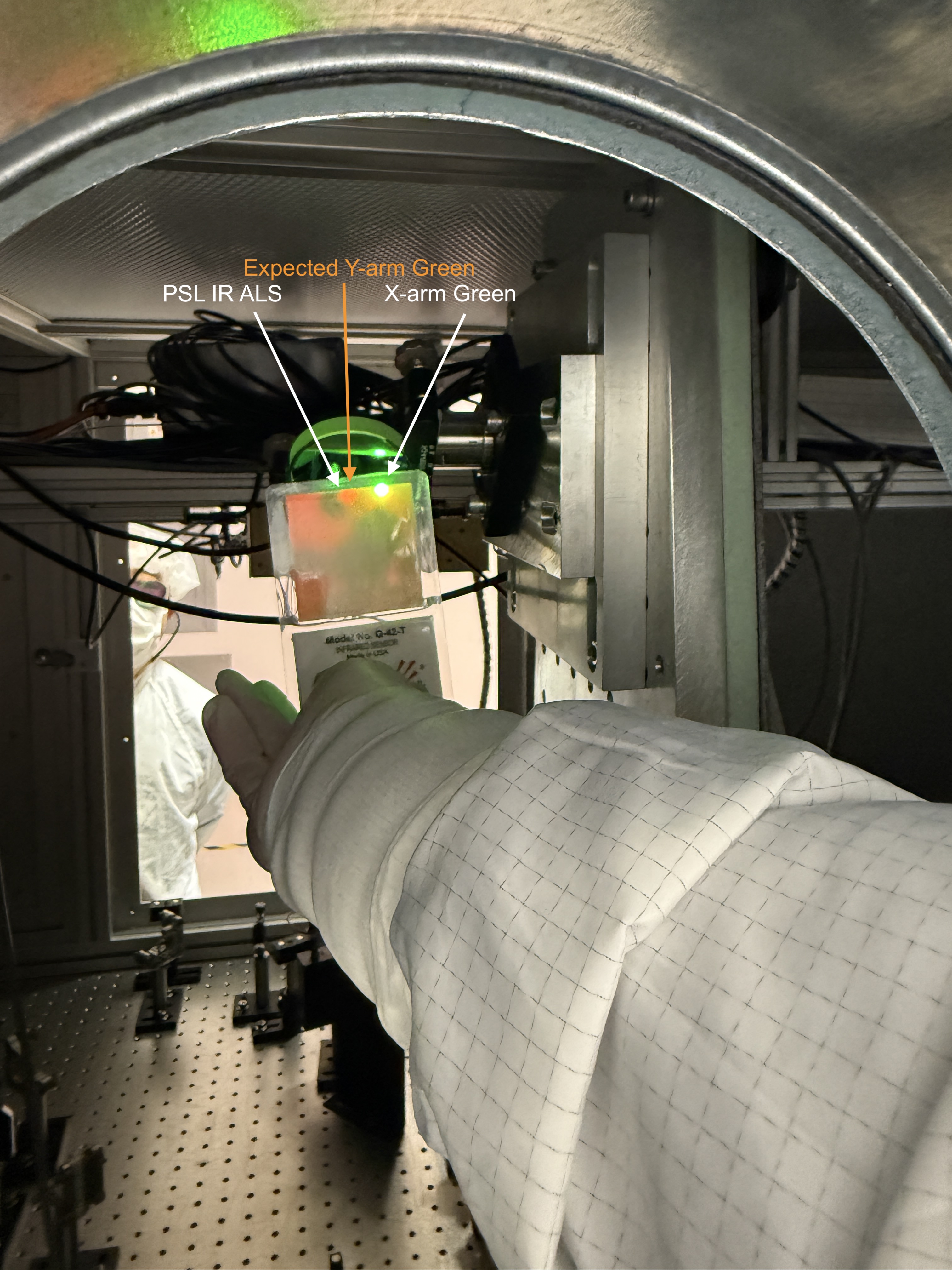
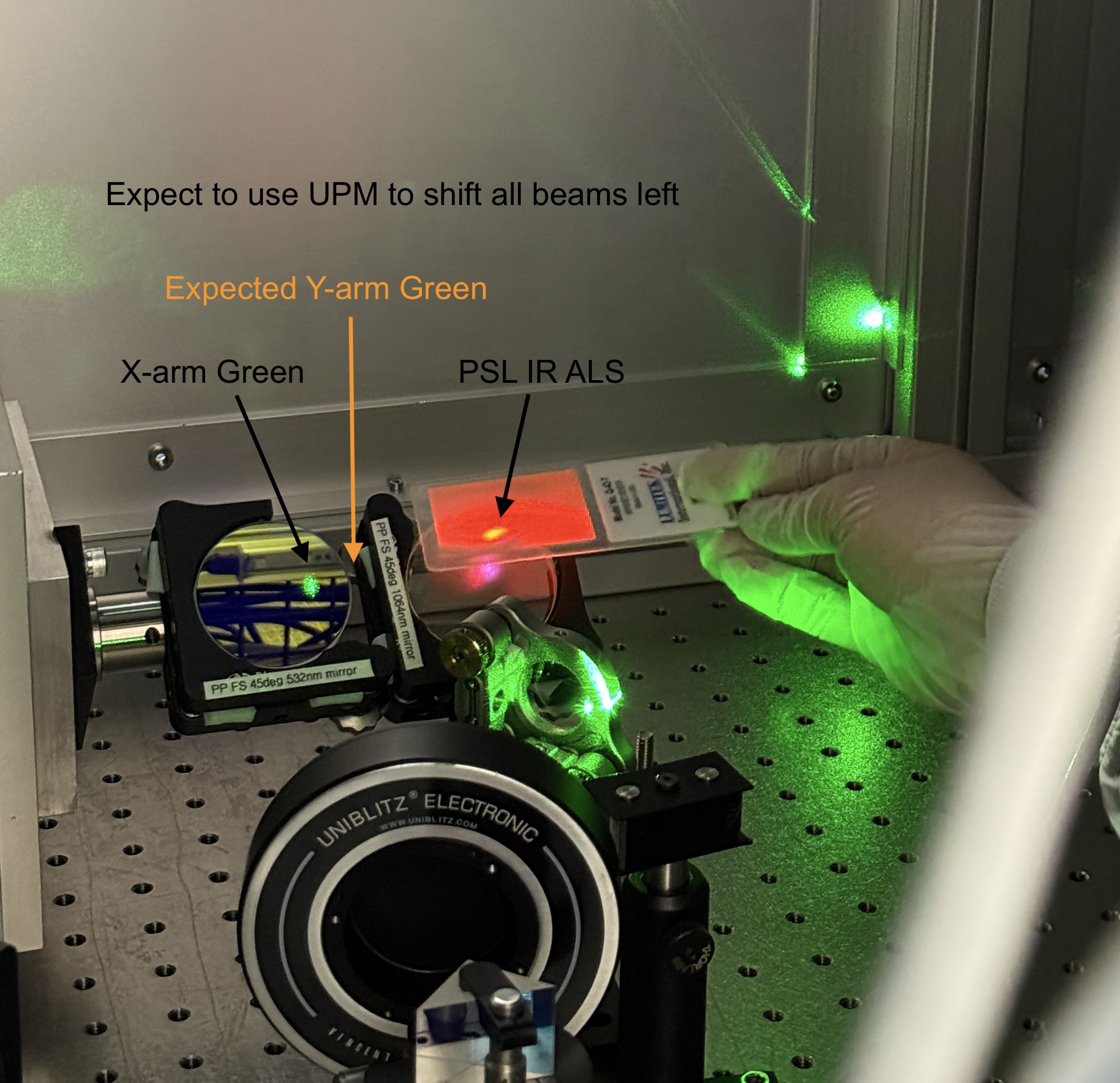
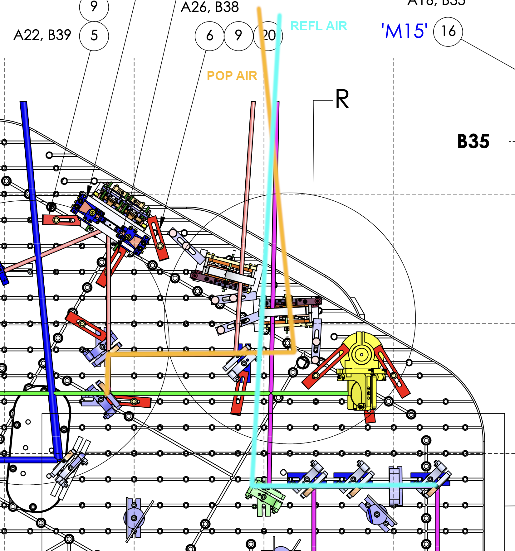
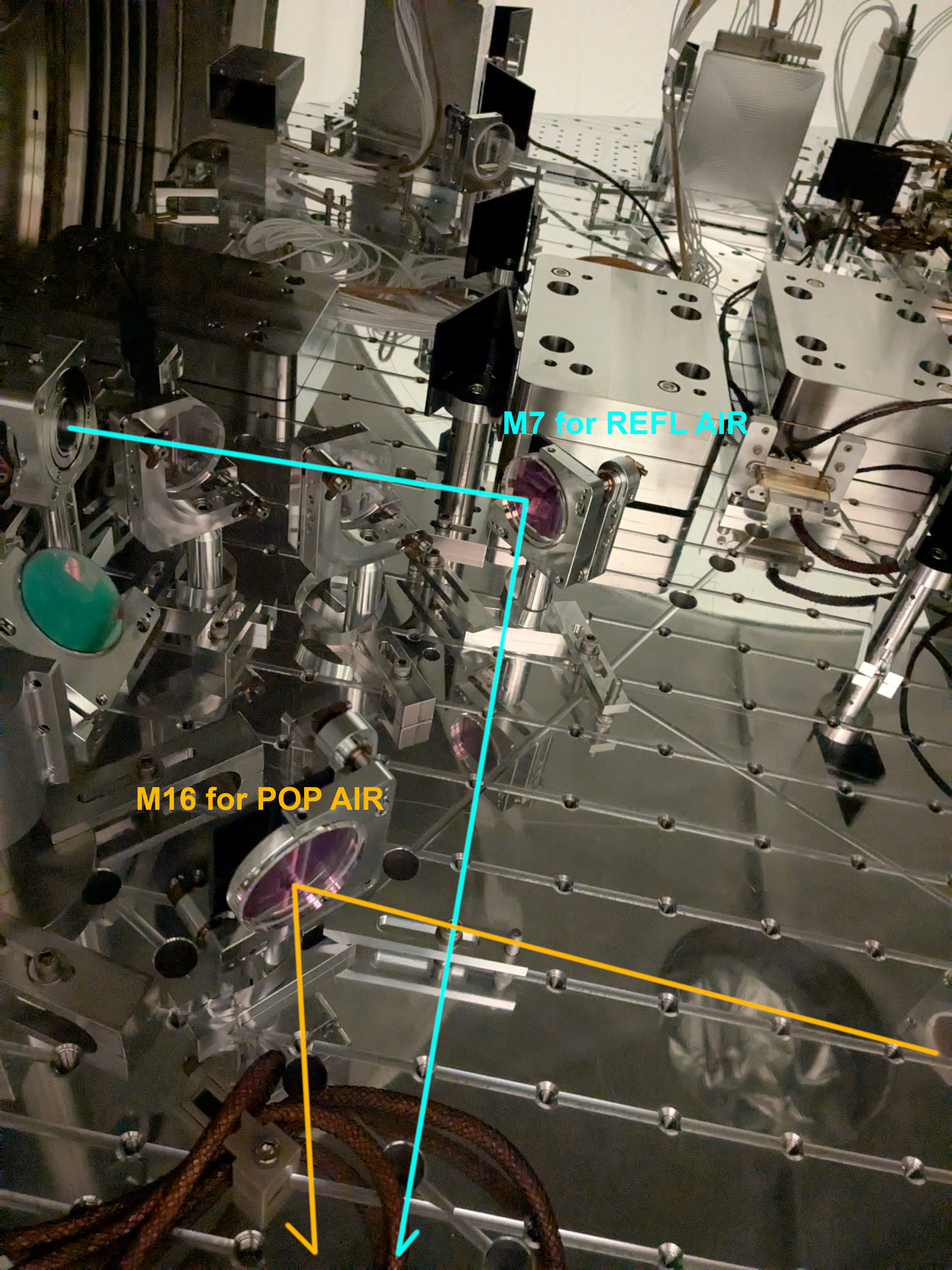
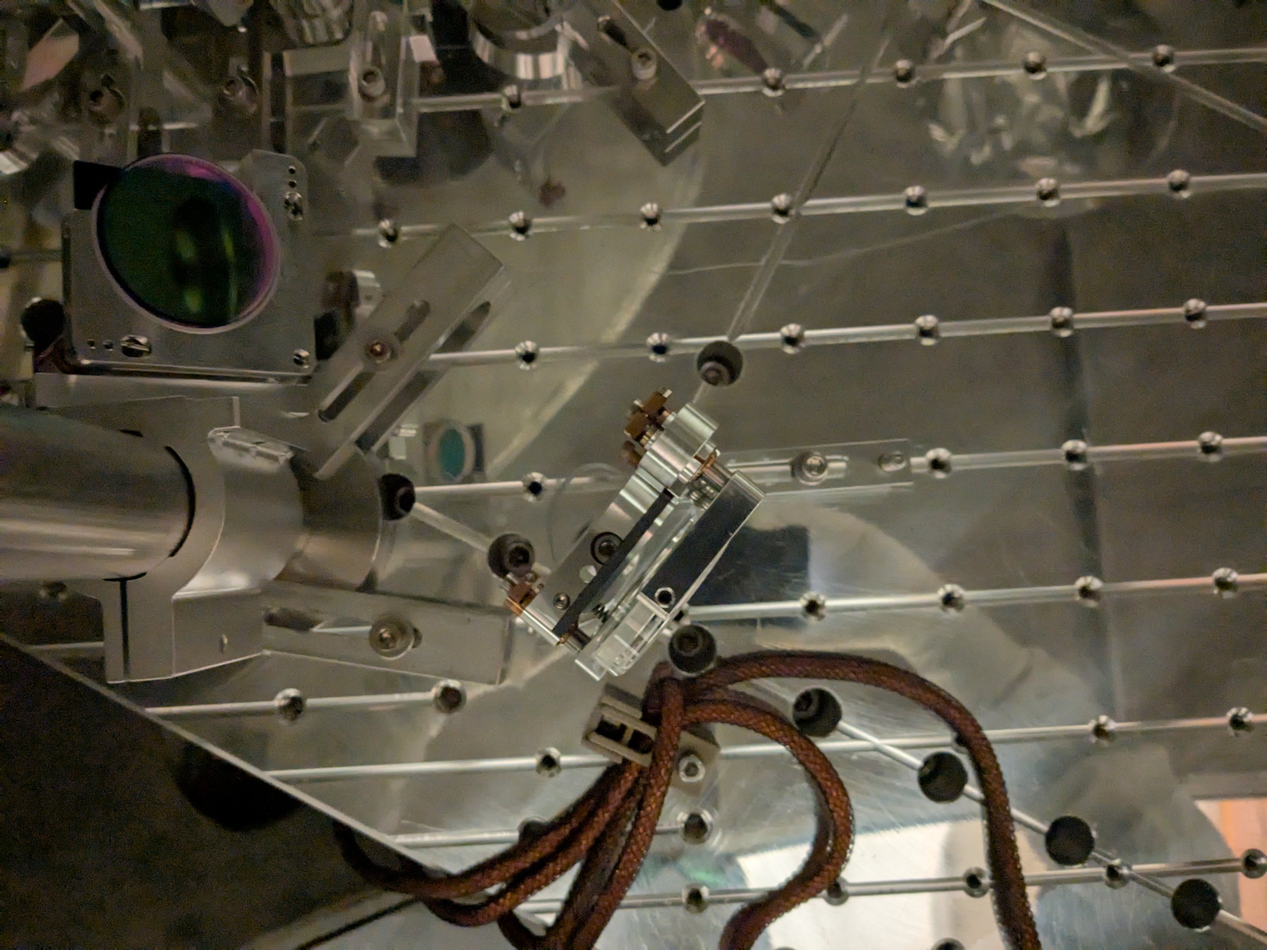
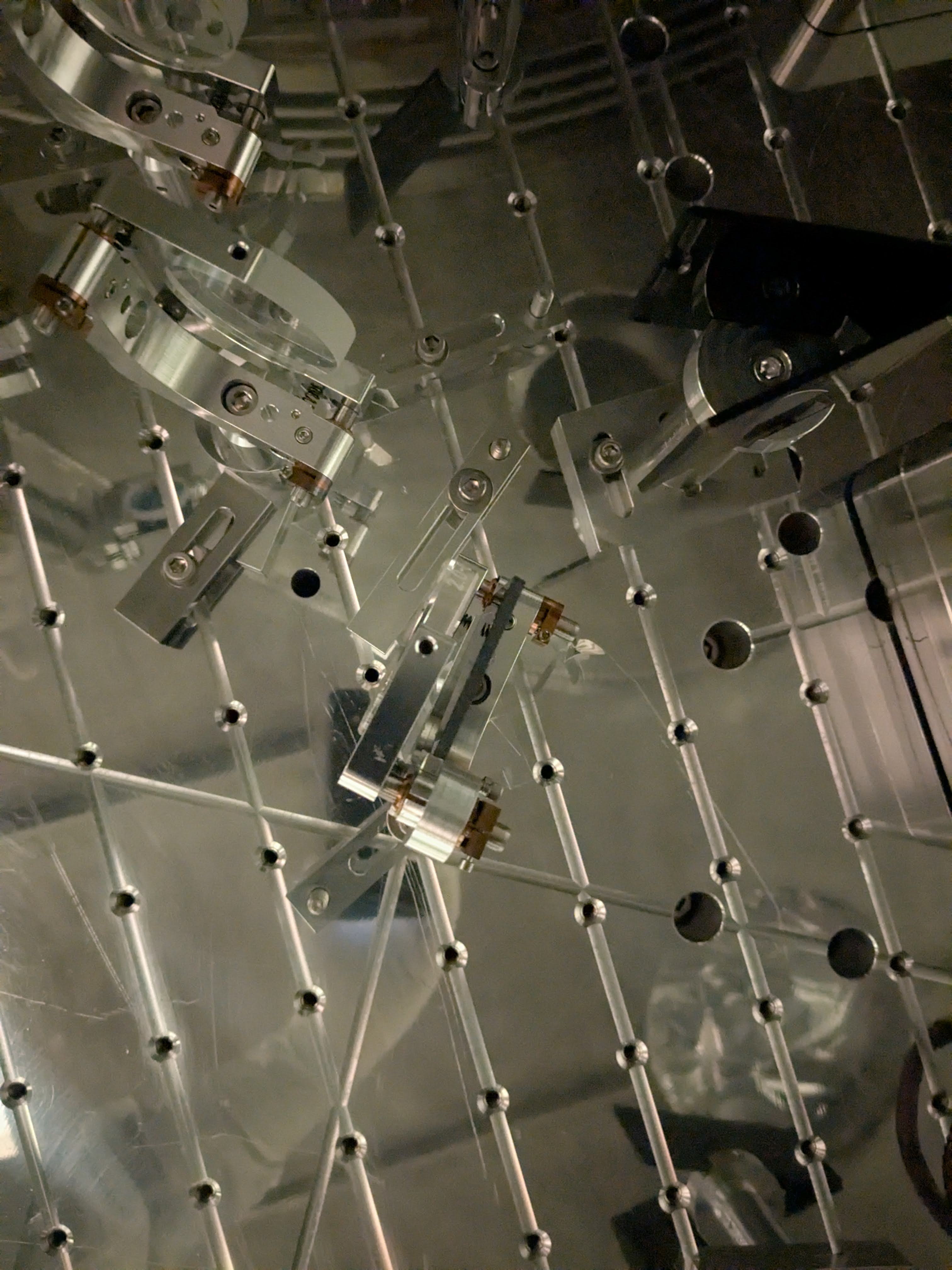
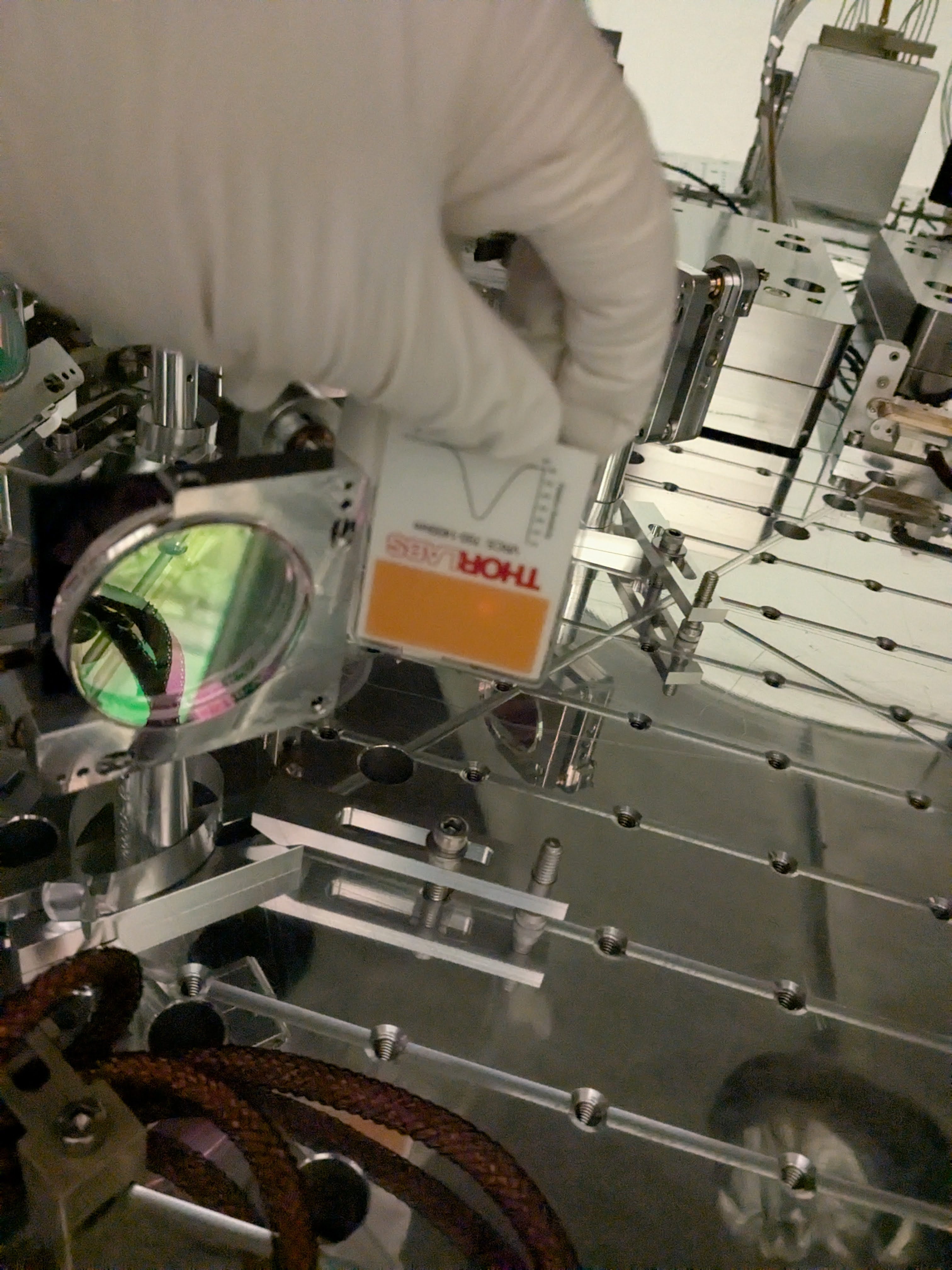
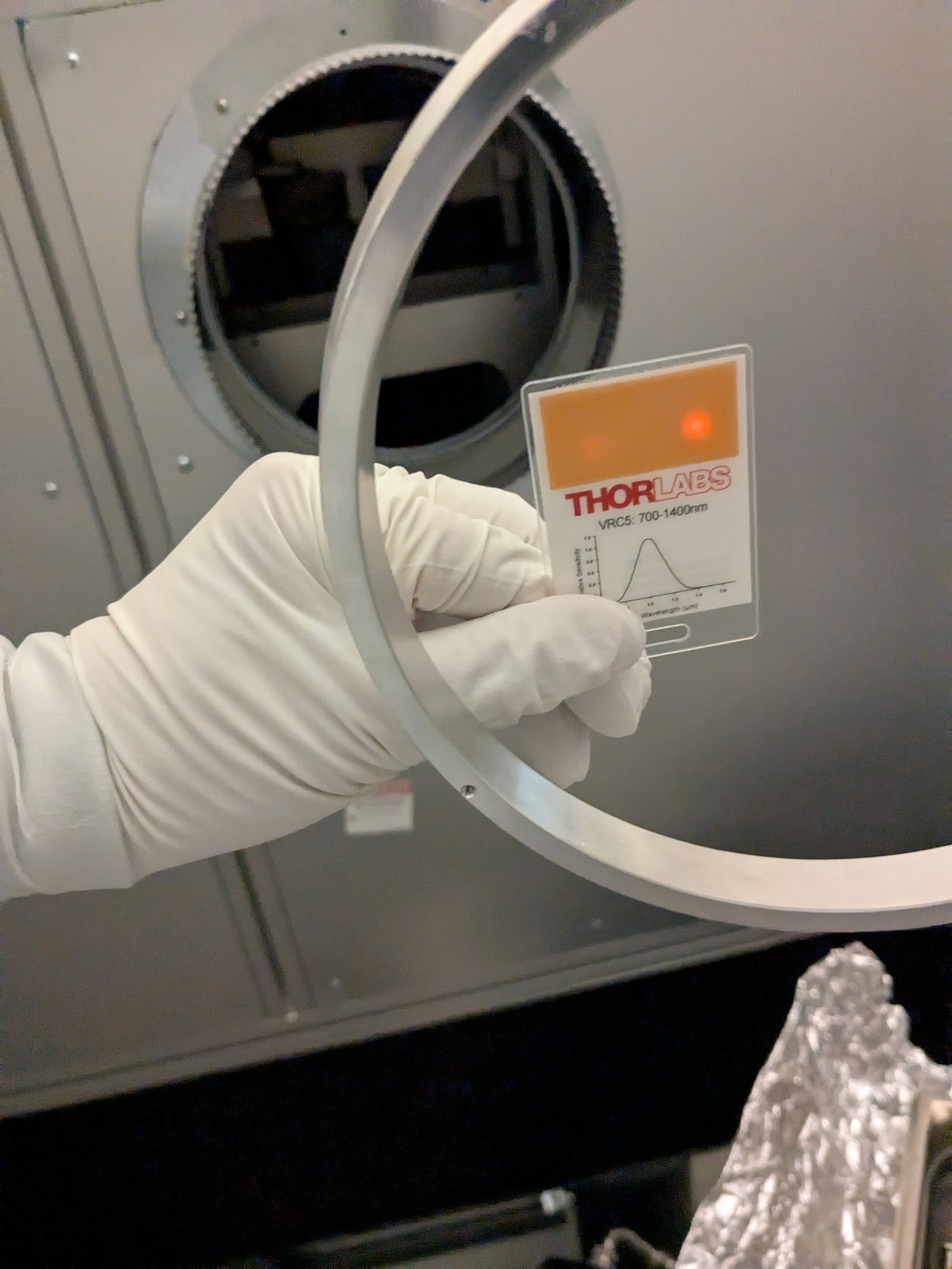
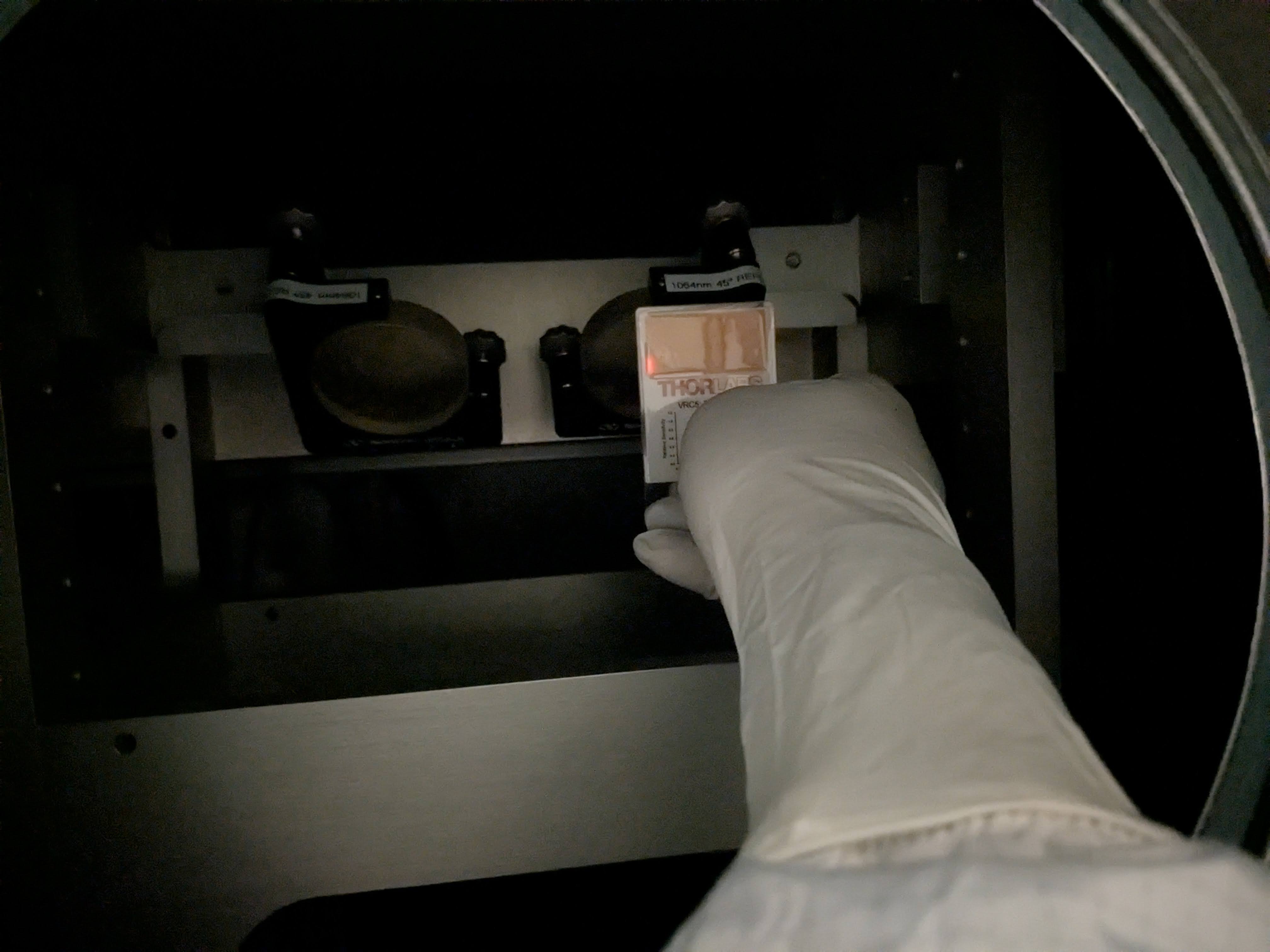
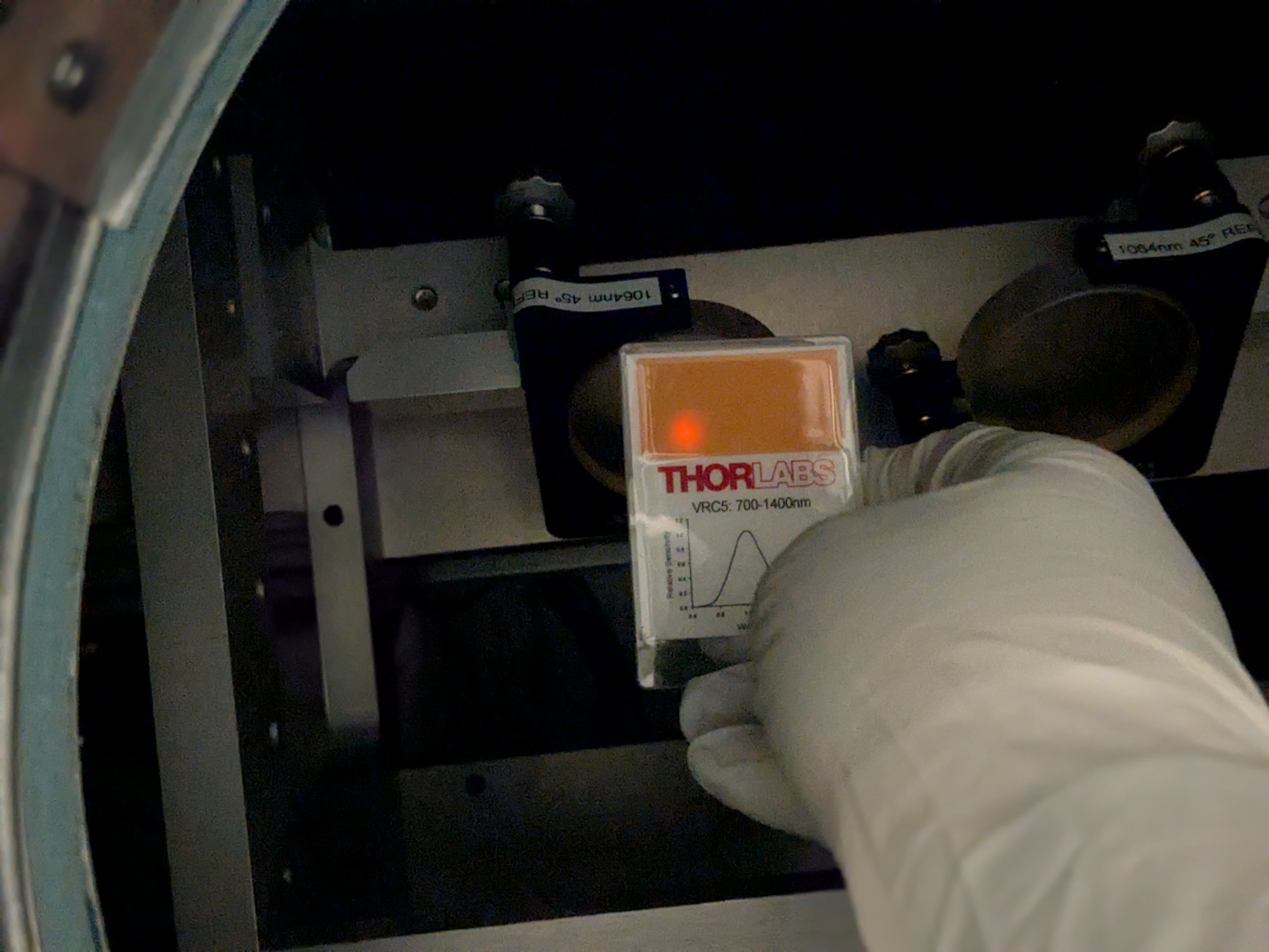
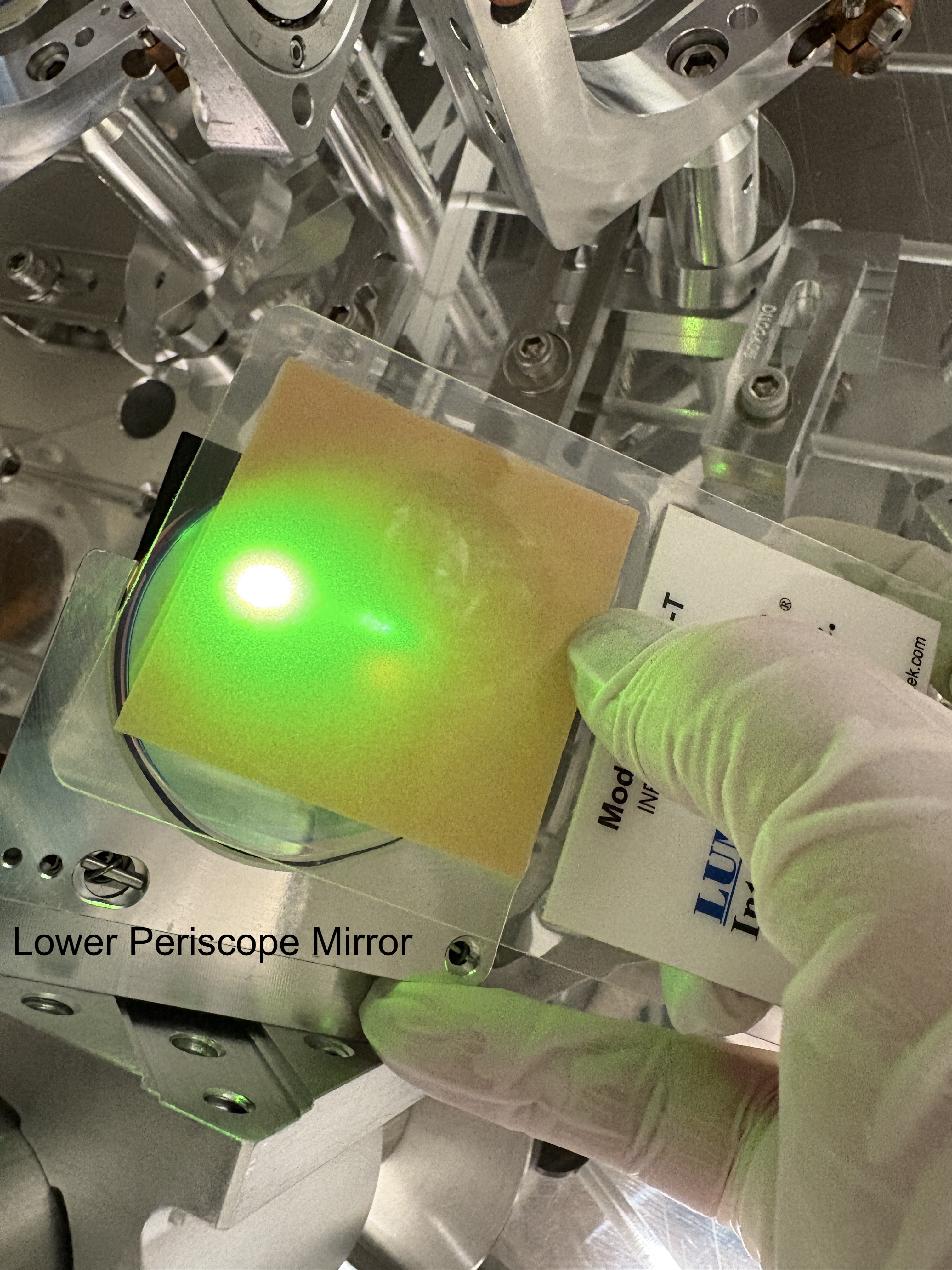
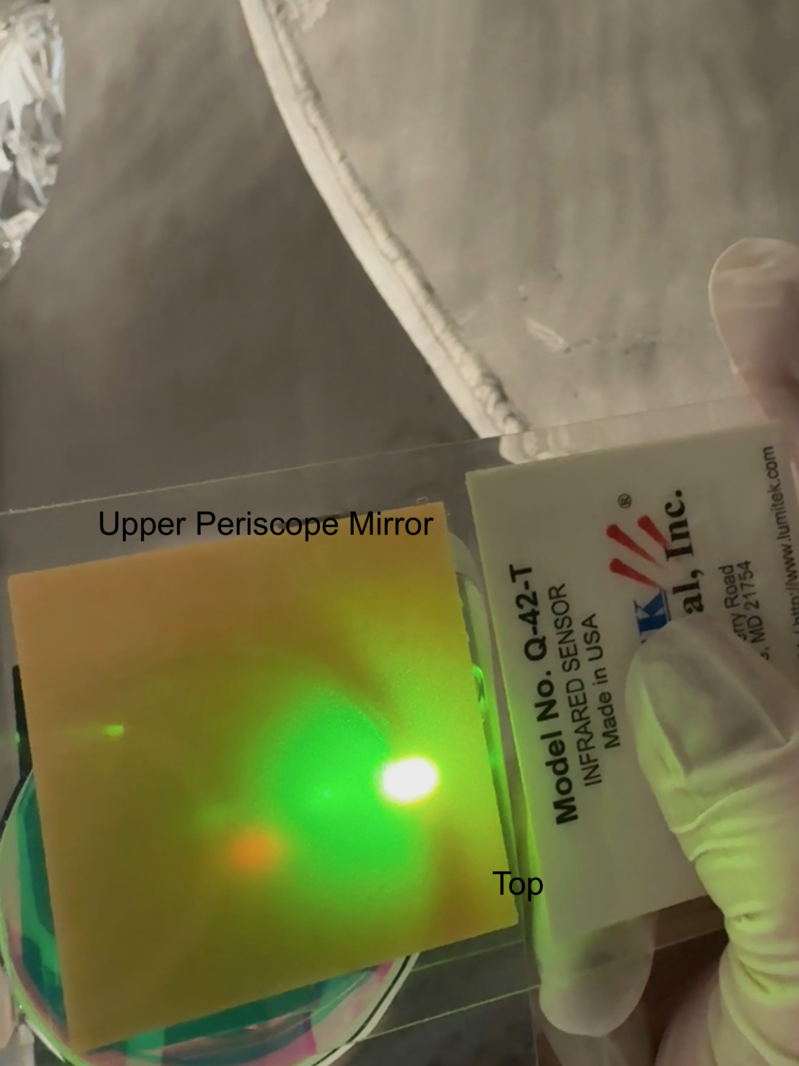
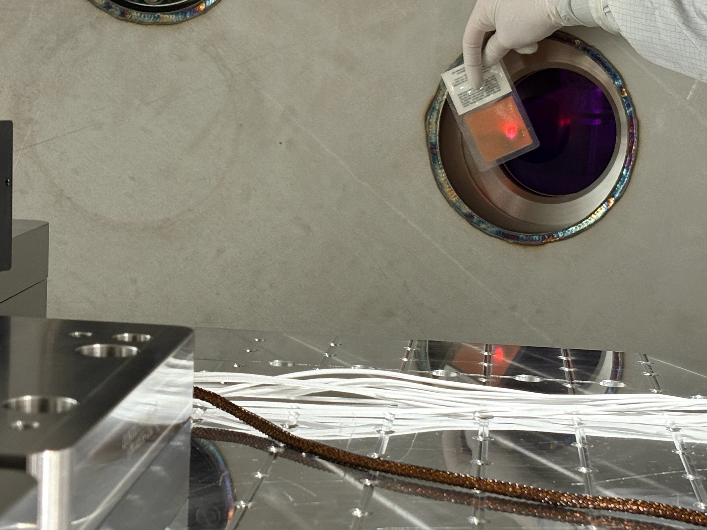
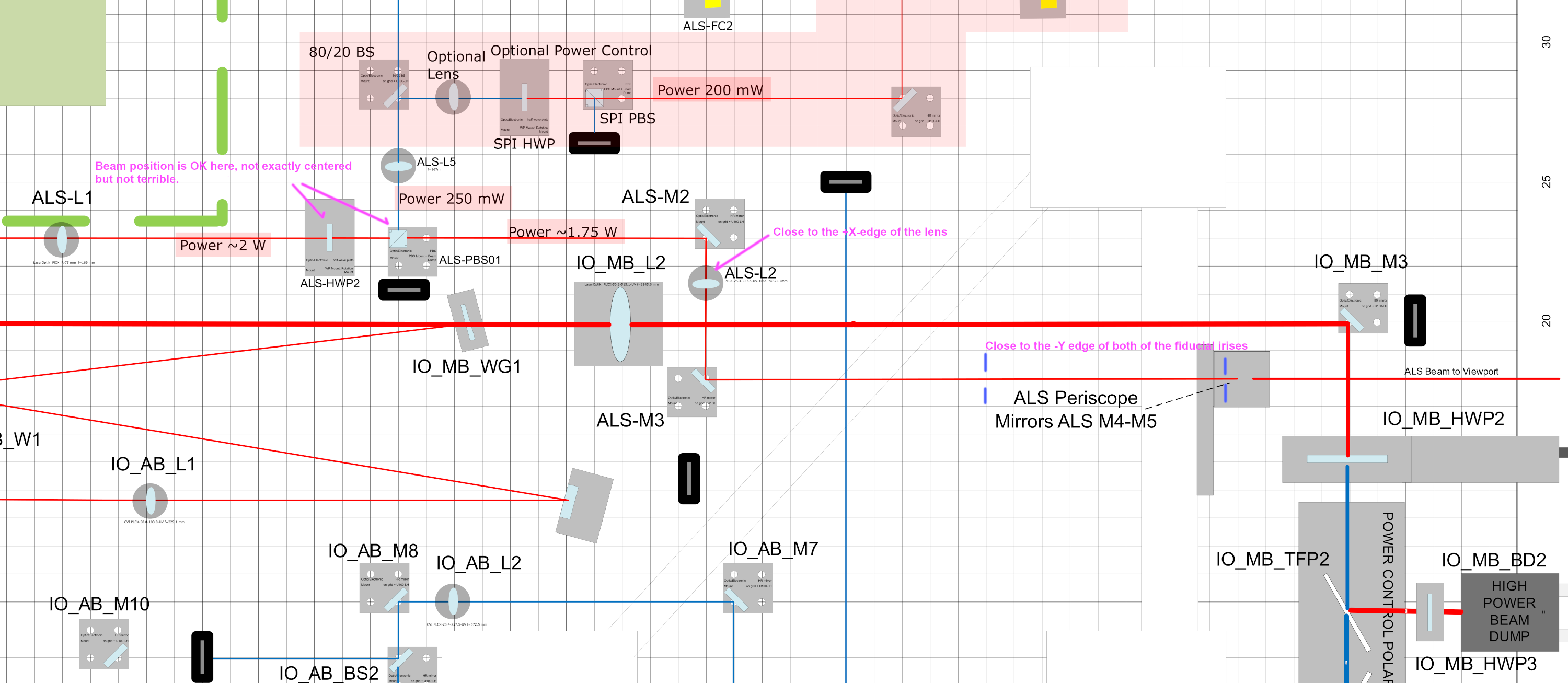
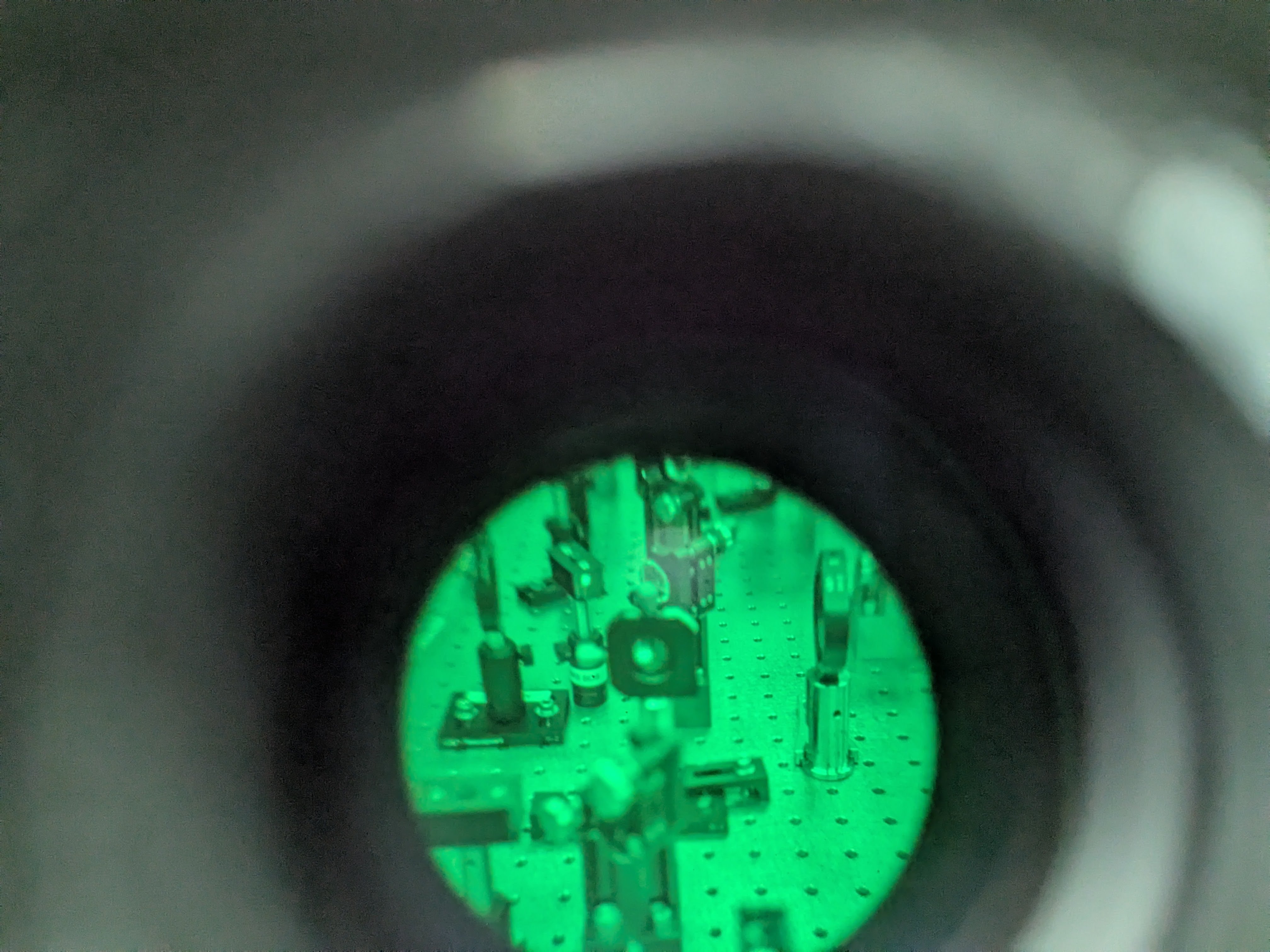
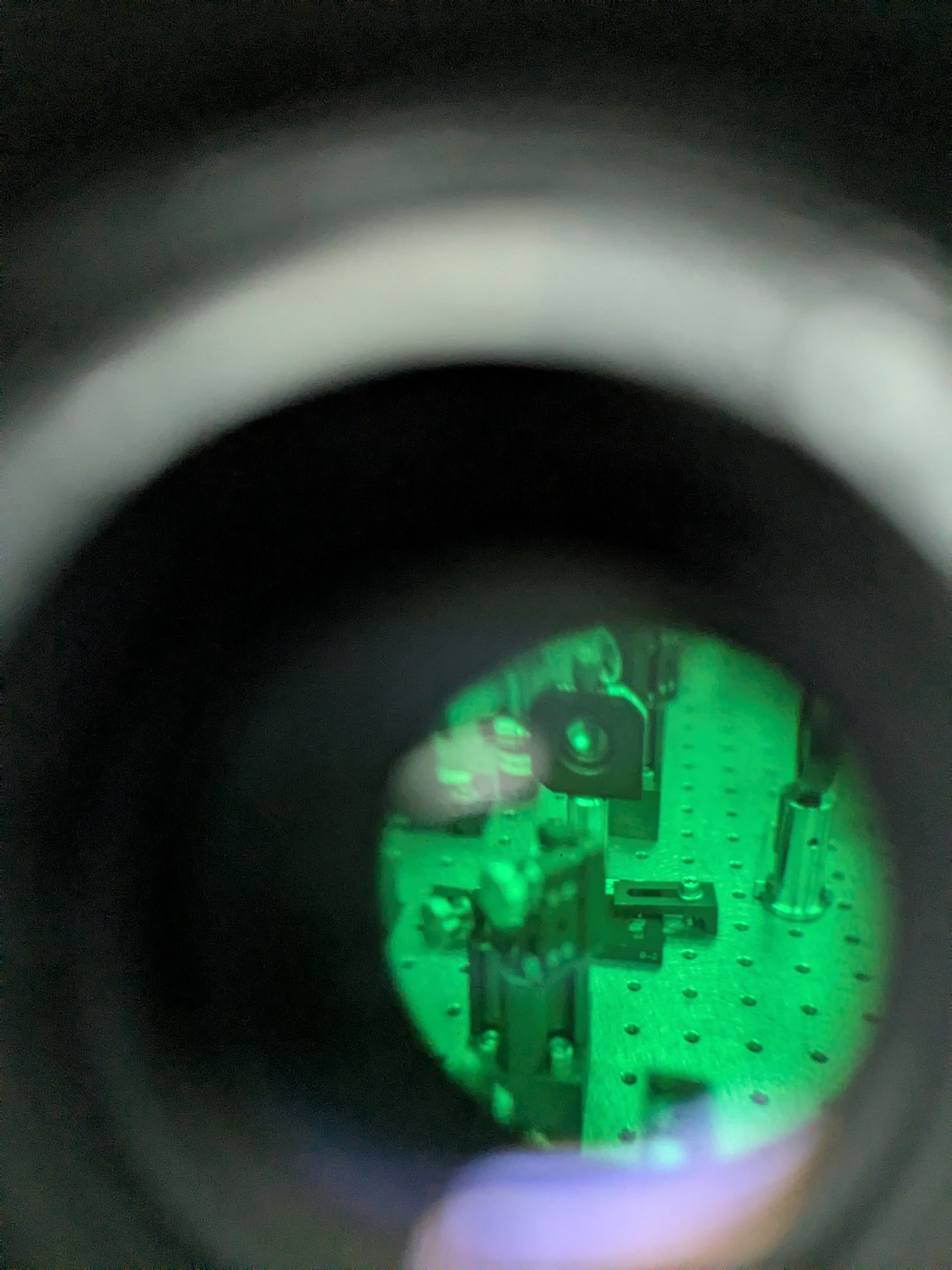
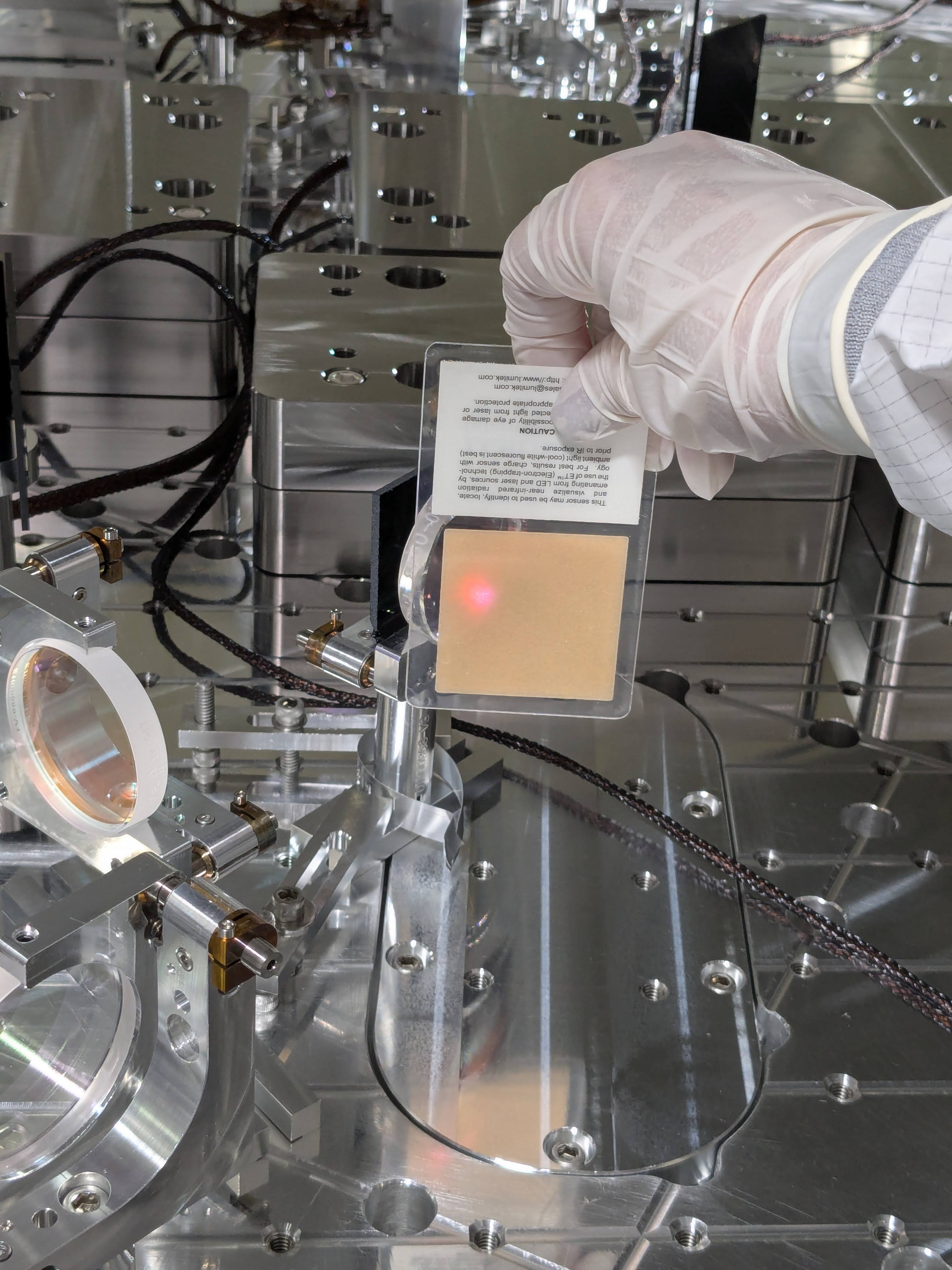
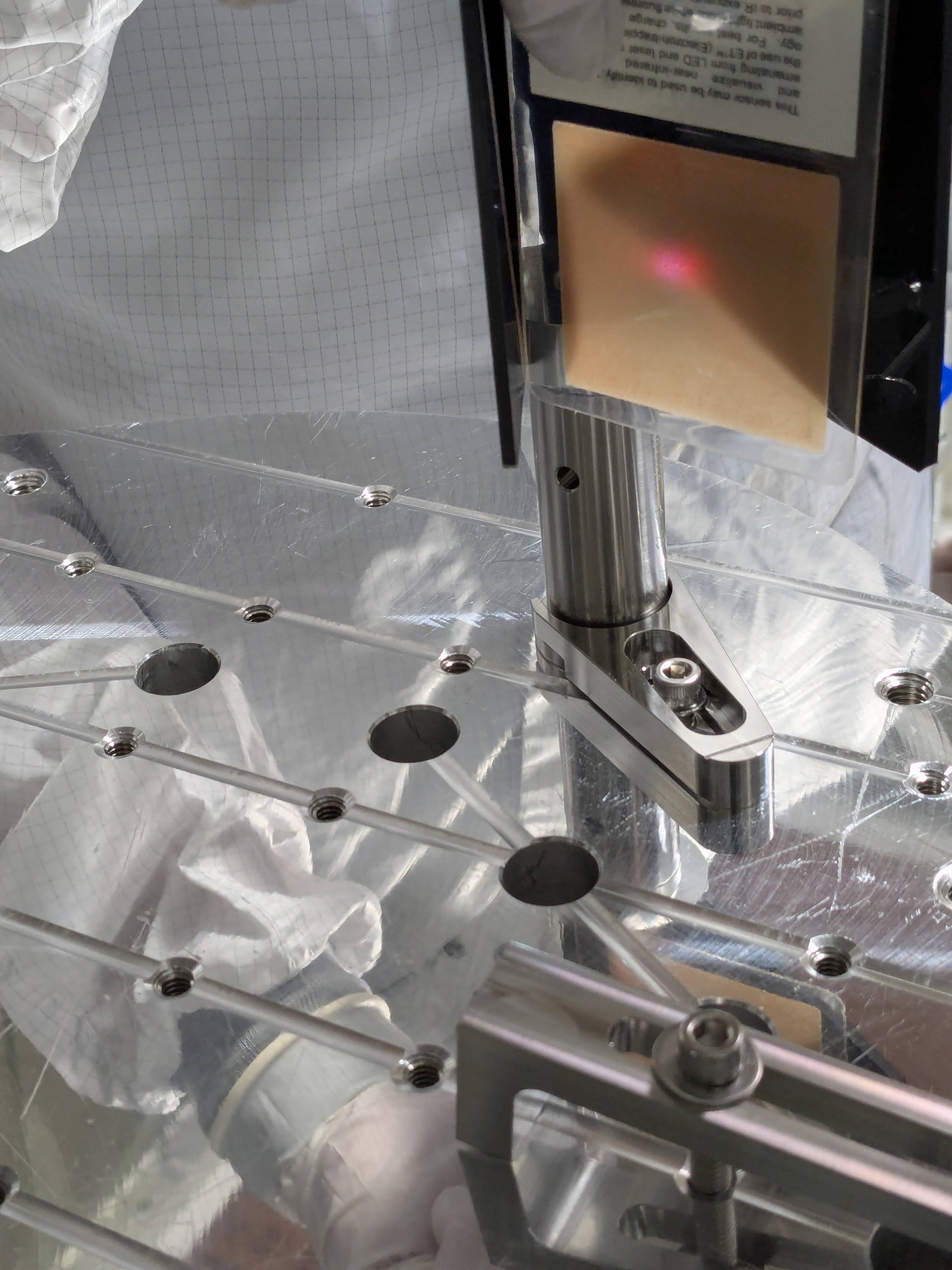
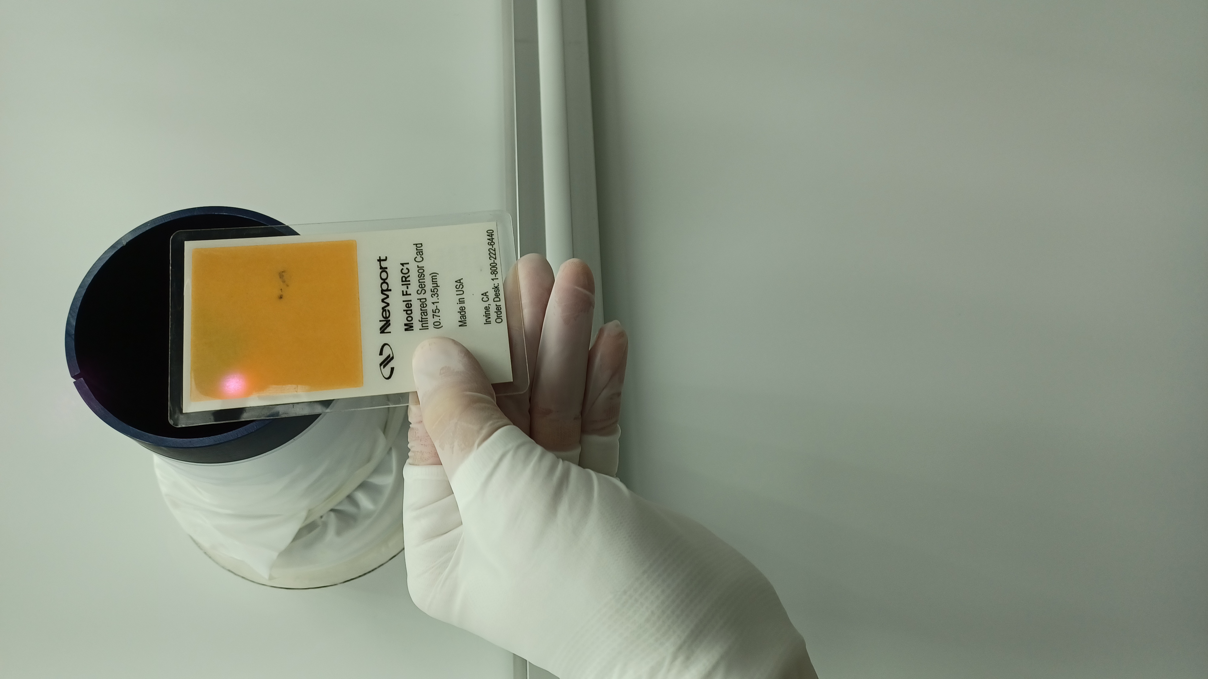
Laser power was turned up at the Request of Camilla & Sheila to aid in finding the IR beam spot alignment on to the ISCT1 table.
Wind fence:
Wind fence team got another set of cables strung up for the WindX work down at End X
GRB-Short E570982 @ 22:34:04 UTC
GRB-Short 570981 @ 22:35:15 UTC
Oli & Camilla took the Laser power back down to 2W for trhe night at 23:39 UTC.
LVEA is still LASER hazard.
LOG:
| Start Time | System | Name | Location | Lazer_Haz | Task | Time End |
|---|---|---|---|---|---|---|
| 15:07 | SAF | LVEA is Laser HAZARD | LVEA | YES | LVEA is Laser HAZARD | 07:07 |
| 14:58 | Bee | Tyler & the BGs | End X | N | Tyler taking the Bee Guy to EX to potentially remove bees | 17:36 |
| 15:21 | FAC | Jim, Randy | EX | N | Working on Wind fence & Bees | 21:08 |
| 15:30 | FAC | Kim & Nellie | LVEA | - | Technical Cleaning | 16:10 |
| 15:38 | ISC | Sheila & Camilla | LVEA HAM1 | Yes | Aligning optics on HAM1 | 19:30 |
| 15:49 | SUS | Rahul | Ham1 | N | Checking for rubbing on RM1 | 16:10 |
| 15:54 | ISC | Keita | LVEA HAM1 | - | talking wwith Sheila | 19:30 |
| 16:25 | PEM | Robert, carlos , Kiet | The Vault in the Desert | N | PEM install work. | 19:58 |
| 17:15 | HAM1 | Betsy | LVEA HAM1 | n | Checking on HAM1 team | 18:43 |
| 17:32 | FCA | Tyler | LVEA Ham1 | N | Moving the ISCT1 table back into place. | 18:11 |
| 19:32 | VAC | Gerardo Y Travis | LVEA +X Arm | - | Soft closing GV7 | 20:08 |
| 19:47 | PCAL | Francisco | PCAL Lab | Yes | Finishing up a measurement | 19:52 |
| 20:19 | SUS | Rahul | Remote | N | Taking RM SUS TF | 21:39 |
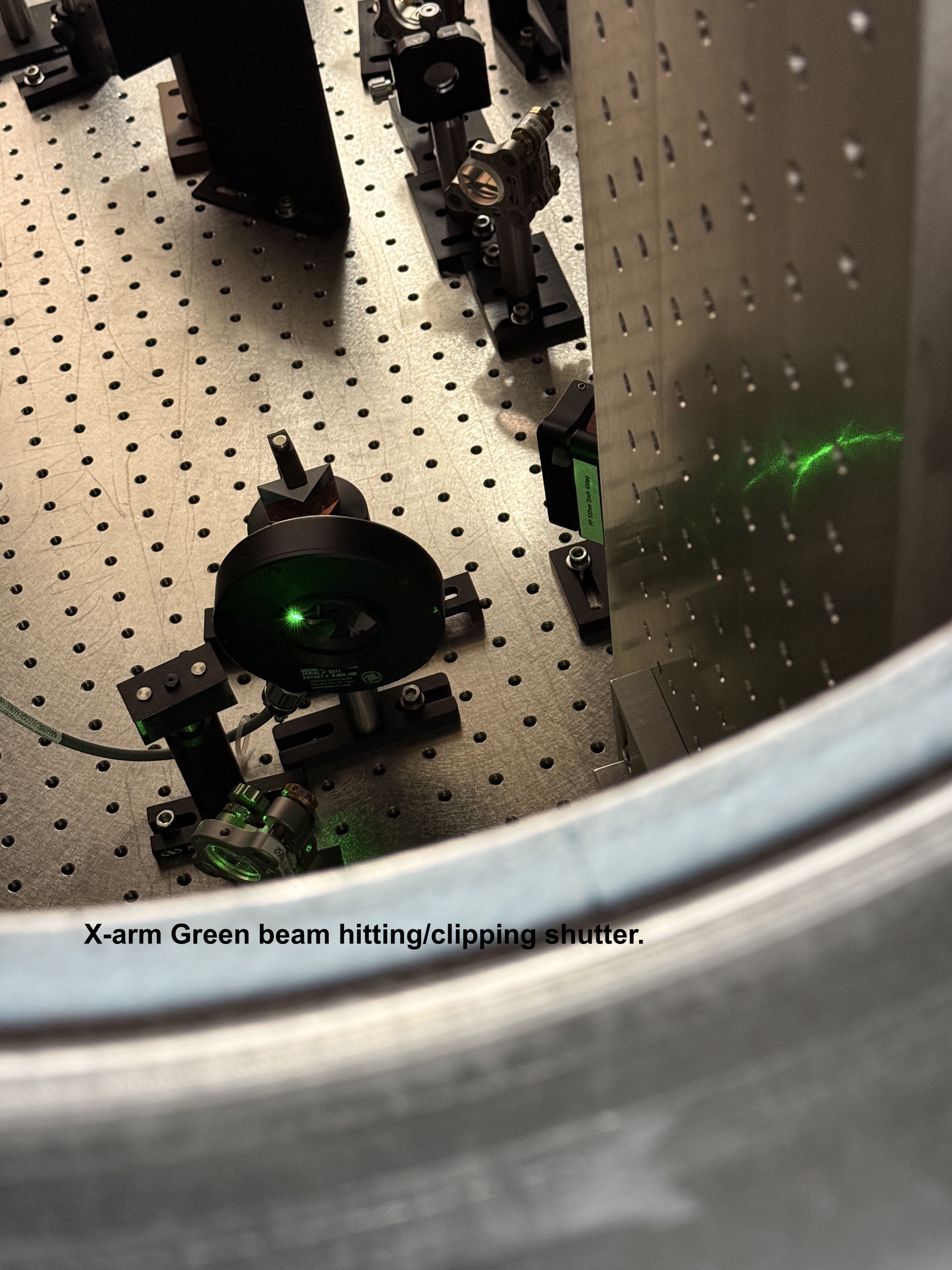
| 20:32 | ISC | Keita & Sheila | LVEA HAM1 | YES | Working on IR beam path inside HAM1 | 00:32 |
| 20:42 | ISC | Jennie W | LVEA HAM1 | Yes | Helping with Beam alignment | 22:44 |
| 21:39 | VAC | Gererdo | LVEA Ham2 +X | N | Decommisioning Optical laver housing | 22:20 |
| 21:56 | PSL | Oli | LVEA | Y | Turn up PSL to 20Ws | 22:05 |
| 21:59 | EE | Marc | MidY | N | Dropping off parts | 22:59 |
| 22:05 | ISC | Camilla | LVEA HAM1 | Yes | Helping with HAM1 work | 23:05 |
| 23:34 | PSL | Oli | LVEA HAM1 | Yes | Turning the power back down to 2W | 23:54 |