vincent.roma@LIGO.ORG - posted 19:57, Sunday 10 January 2016 - last comment - 21:39, Sunday 10 January 2016(24845)
Glitch Harmonics
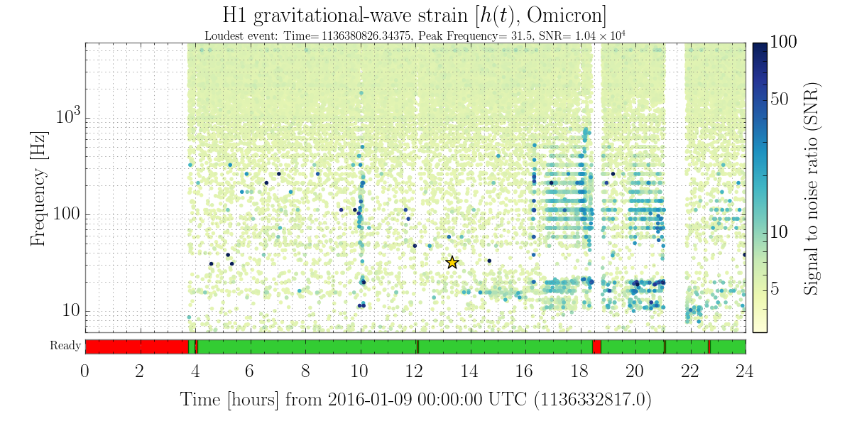
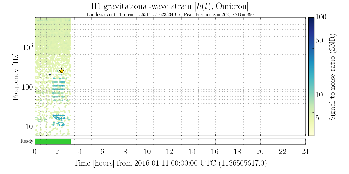
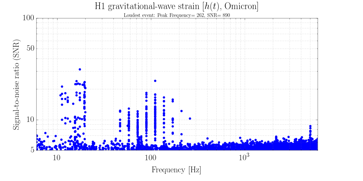
Over the last few days there have been strange glitch patterns that appear to be harmonics of some sort showing up on the summary pages. I've included a few plots showing this from today and yesterday. It's not particularly easy to read off the glitch frequencies sometimes from these plots so I analyzed spectra to try and find the actual frequencies of these glitches. The numbers below came from looking at peaks in a Strain ASD plot. These are estimates, and for a few of them it's hard to tell exactly which peak corresponds to the glitches.
Frequencies [Hz]:
46.1 56.8 70.1 80 113.75 144 (170.5 or 176) 208 256 (302.2 or 303.2)
Images attached to this report
Comments related to this report
I'd asked Vinny to check this out, and am to blame for calling them "harmonics." However, based on the frequencies he's quoted, they're not so harmonic. Attached is a plot of the frequencies and their frequency difference. No two omicron glitch "lines" are exactly harmonic as Vinny suggests. The first few are only roughly 10 [Hz] apart, the next few are 30 [Hz] apart, etc.

My hope was that, if they were harmonic, it would point us to a fundamental frequency which might correspond to a known feature (e.g. the ~10 [Hz] QUAD highest vertical modes) that was modulating other noise at low frequency. Looks like no cigar. However, we've been having these "harmonic"-like omicron triggers for the past several days as Vinny shows, and they can reach several hundreds of Hertz.

I'll caution folks to just dump this in the "RF45 noise" bucket: while we have seen the EOM driver's control servo show coherence with DARM during / surrounding / between when harmonic-like omicron triggers are happening (such episodes usually correspond with a much more gruesome, pattern-free, omicron glitchgram, and a noticeable decay in sensitivity / sensemon range), we've also seen the harmonic-like omicron triggers when there is no coherence between the EOM driver control servo and DARM.

Since this (and the EOM RF frequency control servo) appear to come and go entirely randomly -- has anyone made a comparison with something equally random and unexpected, like ... the space weather?
Non-image files attached to this comment