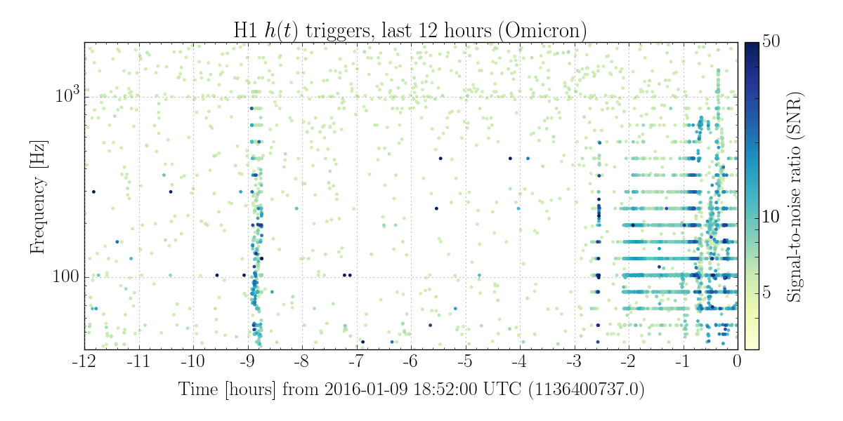
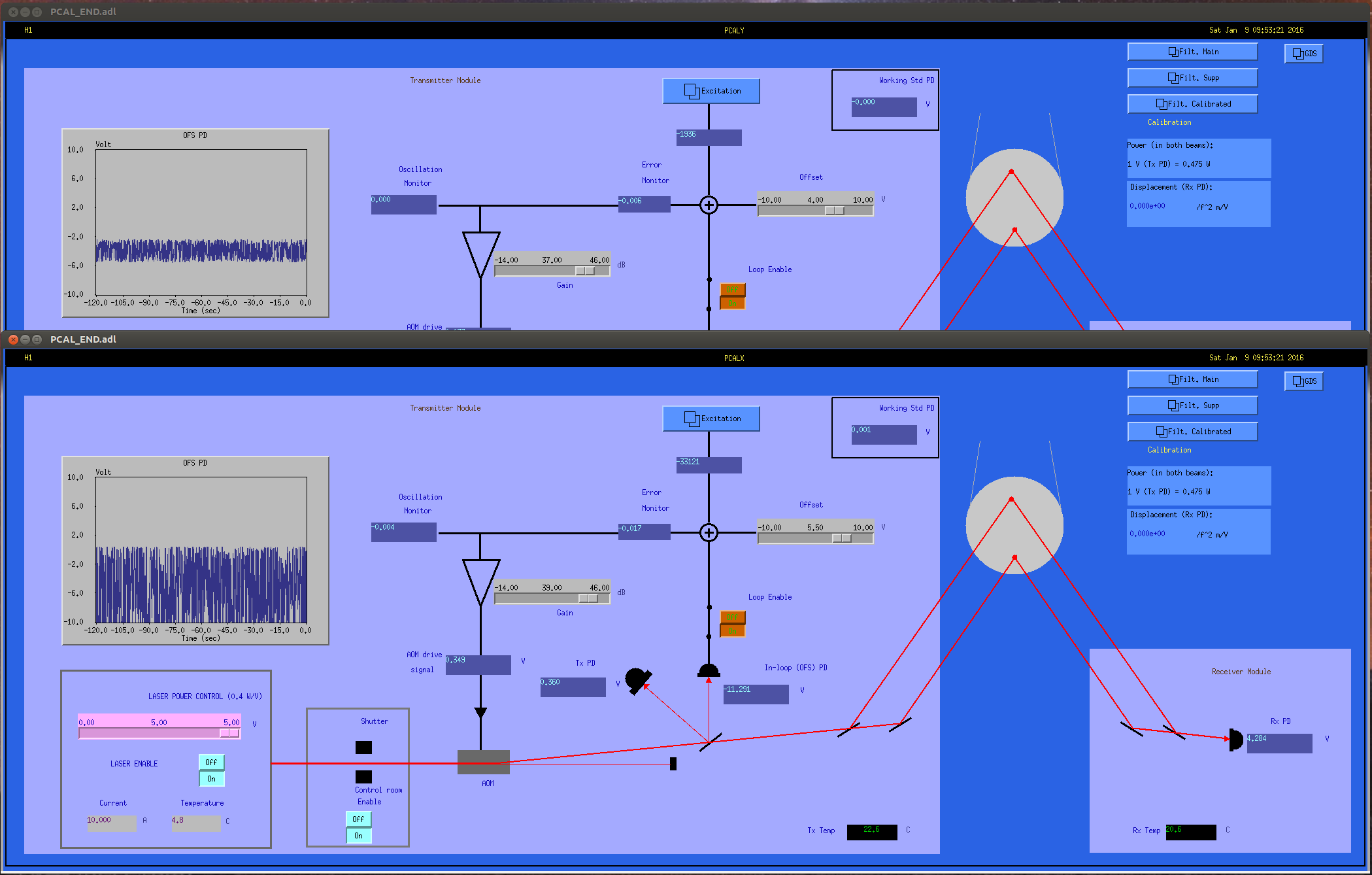
We are using the Xend Pcal to drive the ETM with single-frequency excitations at high frequencies.
Last night, we got about 8 hours at 4001.3 Hz (roughly 8 PM to 4 AM local time)
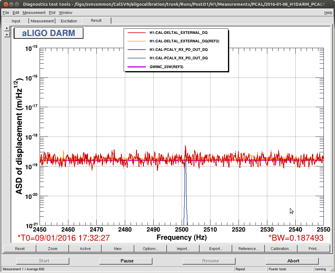
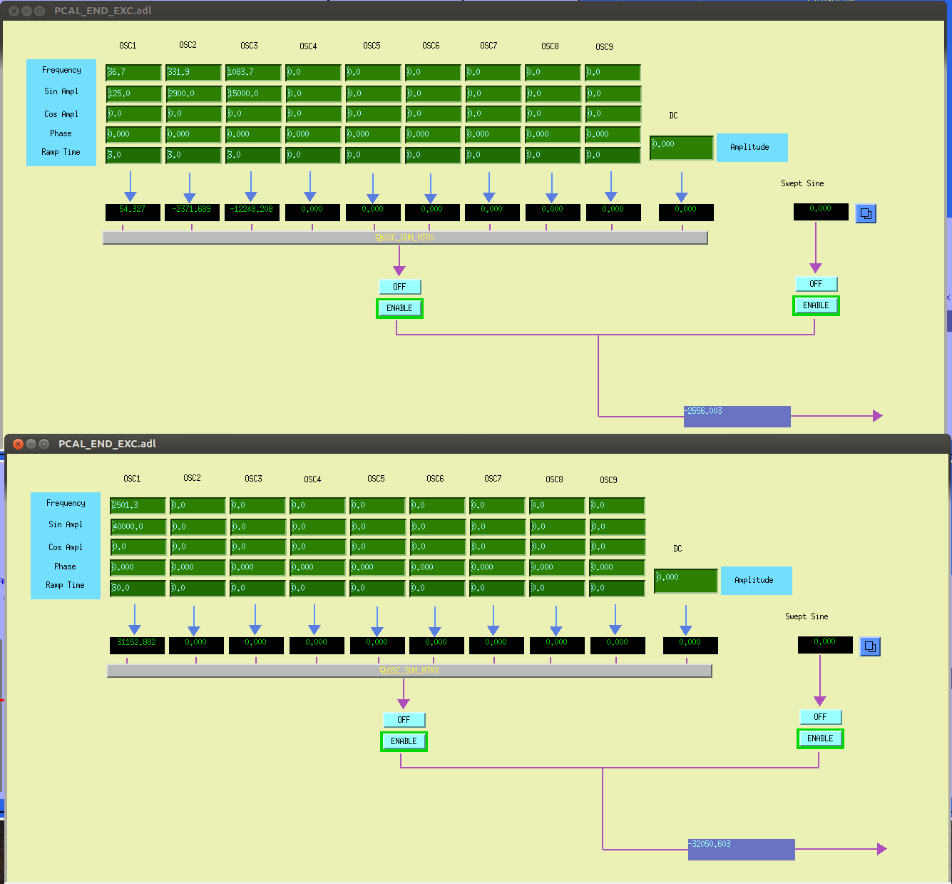
We then shifted to 2501.3 Hz at approximately 4 AM local time and got about 6 hours in this configuration before JeffK just switched to 2001.3 Hz..
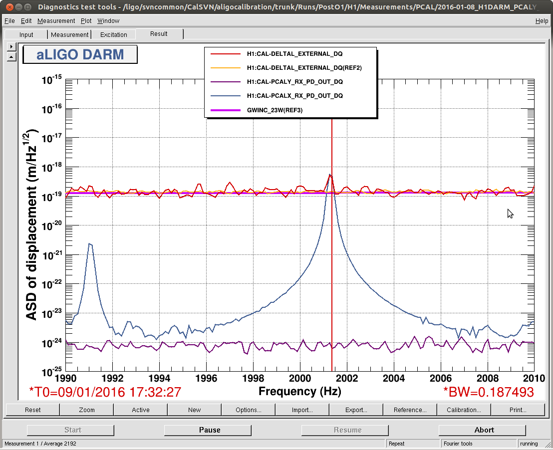
Here is a proposal for frequencies and excitation times, all assuming we are driving the Pcal at close to full range (35,000 - 40,000 counts, in this case)
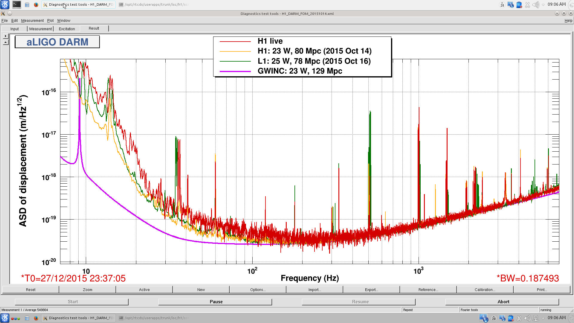
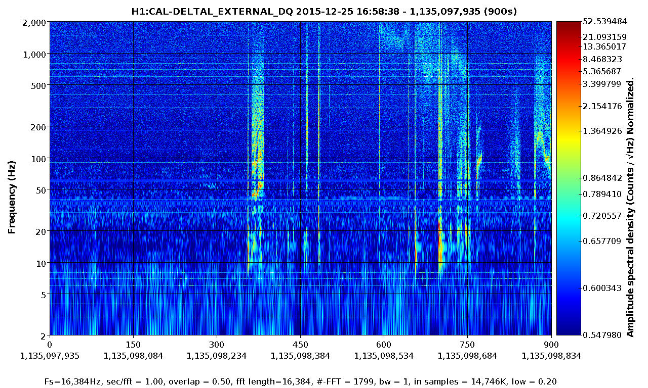
Note that the S/N ratio in DeltaL_external will scale as approximately the inverse of the cube of the frequency.
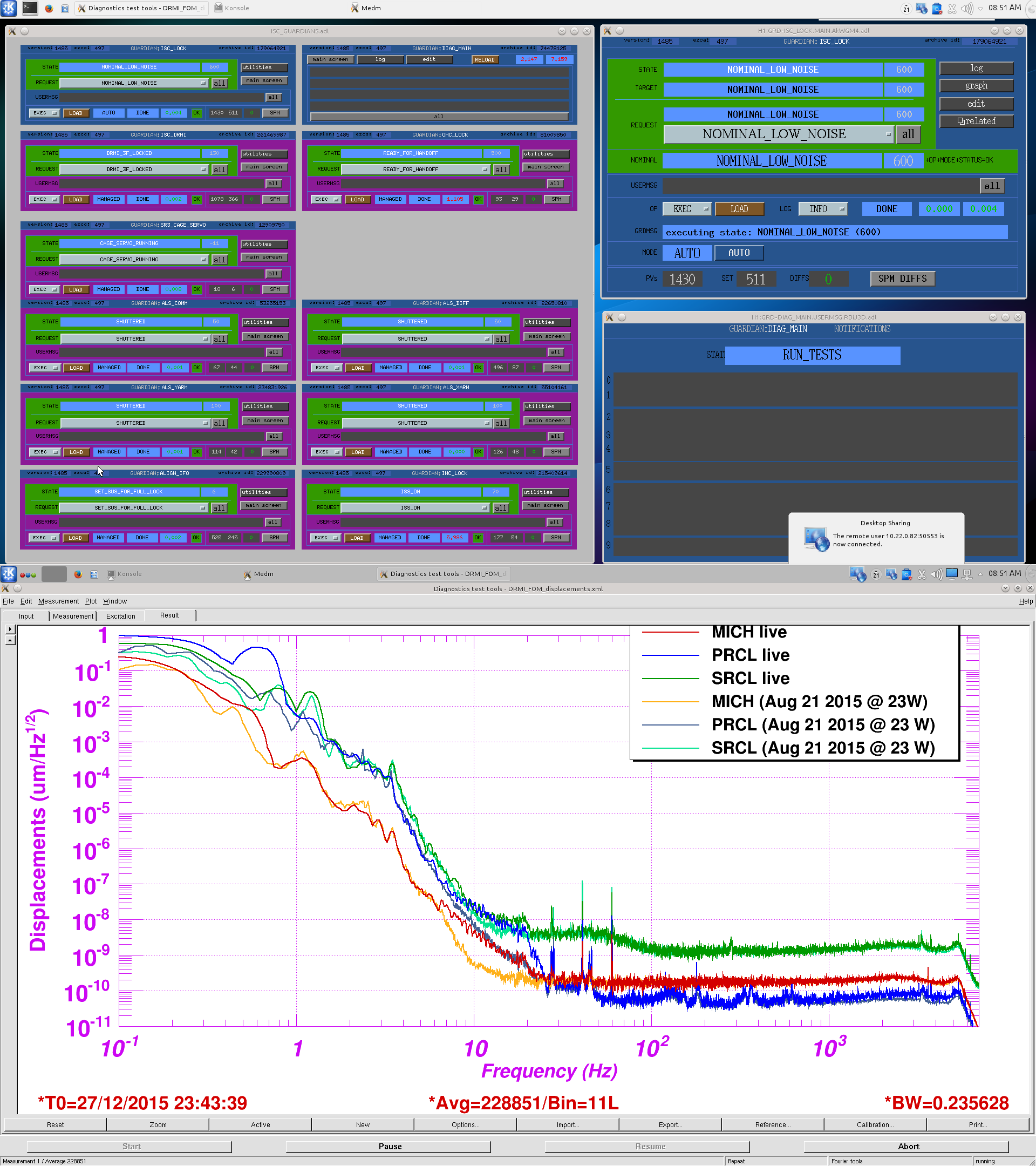
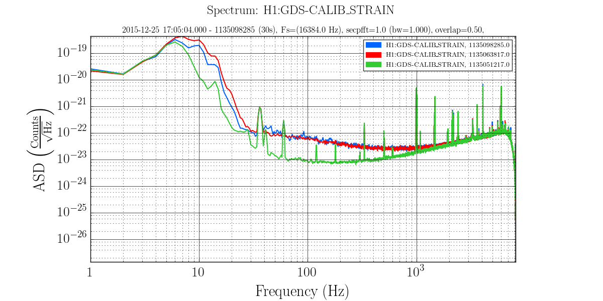
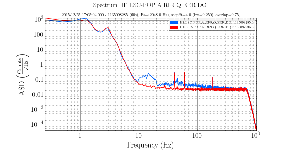
Also note that for each frequency one should scrutinize the DeltaL spectrum to ensure there are no features within a few Hz of the excitation frequency, in which case the excitaiton frequency could be adjusted.
1001.3* Hz 1 hour
1501.3 Hz 1 hour
2001.3 Hz 1 hour
2501.3 Hz 2 hours
3001.3* Hz 4 hours
3501.3 Hz 6 hours
4001.3 Hz 8 hours
4501.3 Hz 12 hours
Note that we already have data near this frequency, so this should be saved until the end, if time allows.
I suggest we run through the lower frequencies (and shorter times) during the days when calibration folks are around to make the changes, then leave the higher frequencies for the evenings with instructions for the operator to make the changes after enough good locked data is obtained.
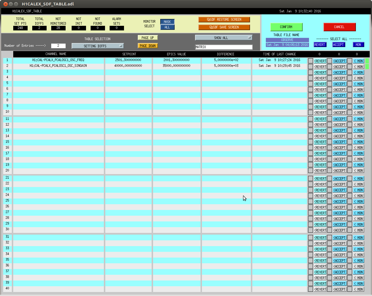
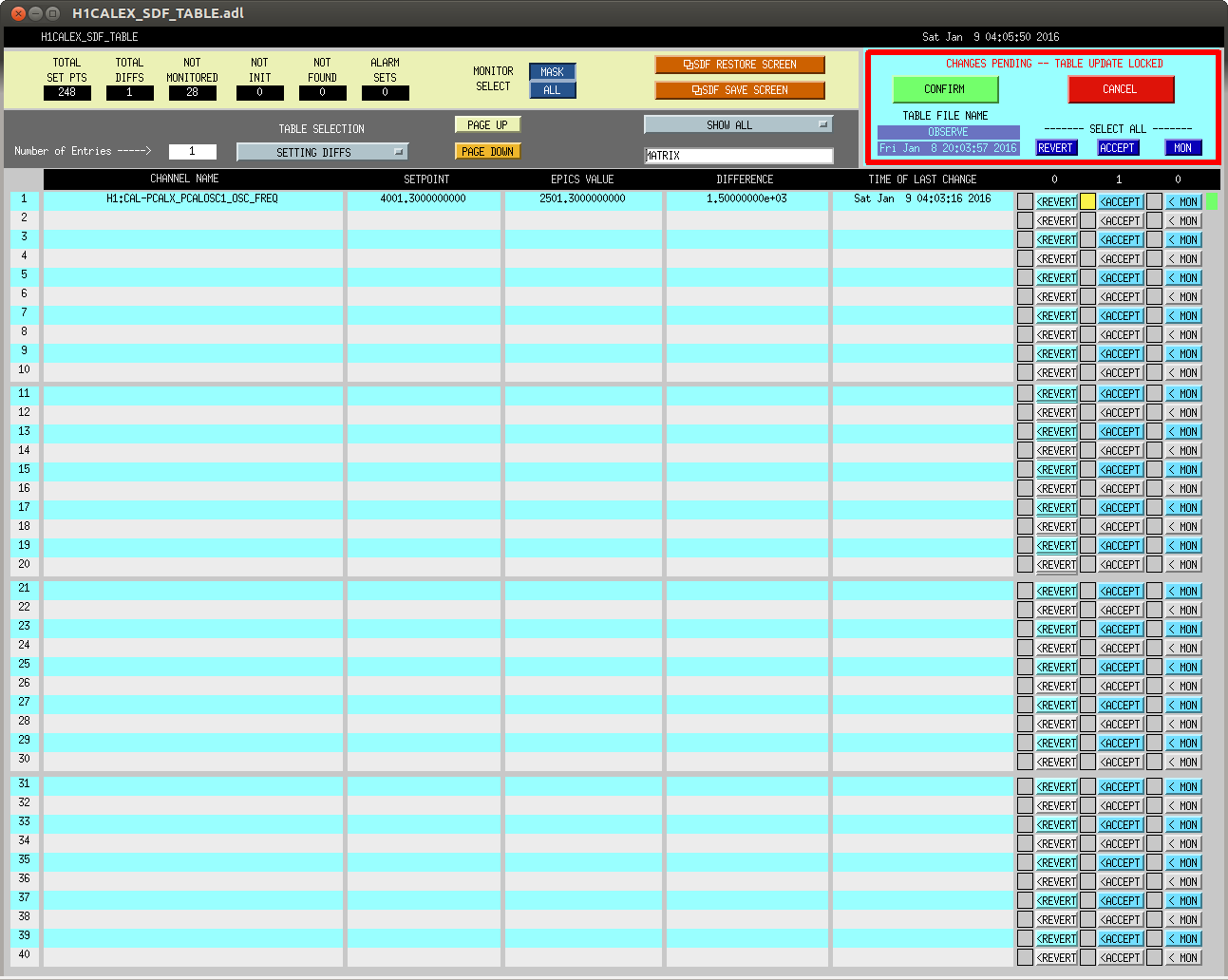
Instructions for changing Pcal drive frequency:
Take ifo out of observing mode
Set Sin Ampl to 0.00, hit return (this should ramp down to zero amplitude, hopefully)
Set frequency to 2501.3 Hz, hit return
Set Sin Ampl to 40000.0, hit return
Accept changes in the SDF system
Set ifo back into observing mode