I have been silently checking the signal chain of the REFLAIR and POPAIR RFPDs using the AM laser (a.k.a. PD calibrator) to make sure that they are functional expectedly.
Summary
-
REFLAIR_A and POPAIR_A looked good as they showed reasonable signal gains
-
On the other hand, REFLAIR_B and POPAIR_B RFPDs showed relatively large discrepancy from the expected values. I might have missed some gain factors somewhere. I will revisit these RFPDs later when I get a chance.
The RF frequency of the AM modulation was adjusted in each measurement such that the demodulated IF signal was below 50 Hz.
Calibration of the amplitude modulation depth
We recalibrated the AM laser.
The current setting of the laser was changed recently because we opened up the current driver when we thought the laser diode had been dead in the early December. Then the laser head and its current driver were sent to Rich at Caltech for his extensive testing although the laser magically fixed itself and he didn't find anything wrong. So this was the first time for us to use the AM laser which had been fixed. Because of that mysterious event, I wanted to recalibrate the laser. First of all, Yuta and I measured the power to be 2 mW with an Ophir Vega without the attenuation filter. Then we measured the modulation depth for the amplitude modulation by using a Newfocus 1611 as a reference.
The new calibration for the amplitude modulation is:
P_am = 5.13 mW x (P_dc / 1 mW) * (1 V / V_drive)
where P_dc is the laser power at DC and V_drive is the drive voltage when it is driven by a 50 Ohm source. For example, if one puts this laser to a PD which then shows a DC laser power of say 2 mW, the AM coefficient is now 5.13 mW x ( 2 mW / 1 mW) /V_drive = 10.26 mW/V_drive.
-
Some details for derivation:
-
DC transimpedance of NF1611= 10k Ohm
-
AC transimpedance of NF1611 = 700 Ohm
-
Responsivity of NF1611 at 980 nm = 0.5 A/W
-
Measured DC voltage = 7.36 mV
-
=> DC laser power of 7.36 mV / 10kOhm / 0.5 A/W = 1.47 uW
-
Measured AC voltage when driven by 0.5 Vpp at 10 MHz = 1.32 mVpp (measured by a 50 Ohm oscilloscope)
-
=> P_am = 1.32 mV / 700 Ohm / 0.5 A/W = 3.771 uW
-
=> AM coefficient is 7.54 uW / V_drive
-
Therefore the AM calibration is:
-
7.54 uW / 1.47 uW x 1 mW = 5.13 mW x (P_dc / 1 mW) * (1 V / V_drive)
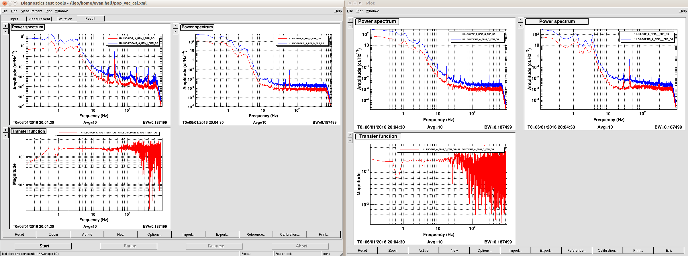
REFLAIR_A_RF9 (S1203919)
Remarks:
The signal chain is OK. The PD response is smaller by 15% for some reason.
It seems as if the transimpedance is smaller by 15% than what had been measured at Caltech (LIGO-S1203919). The cable loss from the RFPD to the rack was measured to be 0.47 dB. Be aware that the demod gain is half of the quad I/Q demodulator because this is a dual channel demod (see E1100044). The demod conversion gain is assumed to be 10.9 according to LIGO-F1100004-v4.
-
Measured DC at BNC jack = 108 mV
-
DC laser power = 108 mV / 100 Ohm / 0.67 A/W = 1.61 mW
-
Expected AM signal when driven by 0.1 Vpp = 5.13 mW x (1.61 mW / 1 mW) x 0.1 Vpp x 0.67 A/W x 245 Ohm = 135.6 mVpp
-
Measured AM signal at the SMA jack of the RFPD enclosure = 115 mVpp
-
This is already smaller by 15%.
-
If we blame the transimpedance, it must be 208 Ohm rather than 245 Ohm.
-
Measured AM signal at the rack = 109 mVpp
-
Expected IF signal = 135.6 mVpp x 10.9 / 2. = 622 mVpp
-
Measured IF signal = 570 mVpp
-
If we take the 15% and 0.47 dB losses into account, we would expect this to be 527 mVpp.
-
Expected ADC counts = 135.6 mVpp x 10.9 x 2^16 counts /40 V x 1/2 = 1209 counts pp
-
Measured ADC counts = 900 counts pp
-
If we take the 15% and 0.47 dB losses into account, we would expect this to be 973 counts pp.
-
This is within 10% divation. Good enough.
REFLAIR_A_RF45 (S1203919)
Remarks:
The signal chain is healthy.
Found cable loss of about 1.5 dB. The measurements excellently agree with the loss-included expectation.
-
DC laser power = 1.61 mW (the same as REFLAIR_A_RF9)
-
Expected AM signal when driven by 0.1 Vpp = 5.13 mW x (1.61 mW / 1 mW) x 0.1 Vpp x 0.67 A/W x 341 Ohm = 188.7 mVpp
-
Measured AM signal at the SMA jack of the RFPD enclosure = 190 mVpp
-
Measured AM signal at the rack = 160 mVpp
-
Corresponds to loss of 1.5 dB
-
Expected IF signal = 188.7 mVpp x 10.9 = 1028 mVpp
-
If the loss is taken into account, it is going to be 1028 mVpp x -1.5 dB = 865 mVpp
-
Measured IF signal = 880 mVpp
-
Consistent with the loss-included expectation
-
Expected ADC counts =1028 mVpp x 2^16/40 x 2 = 3369 counts pp
-
If the loss is taken into account, it should be 3368. x -1.5 dB = 2837 counts pp
-
Measured ADC counts = 2784 counts pp
-
Good agreement with the loss-included model
POPAIR_A_RF9 (S1300521)
Remarks:
The signal chain is healthy.
The measurement suggests that there is loss of 1 dB somewhere. I didn't measure the cable loss this time.
-
Measured DC at the BNC jack = 95.6 mV
-
Estimated DC laser power = 95.6 mV / 100 Ohm / 0.67 A/W = 1.42 mW
-
Expected AM signal = 5.13 mW x (1.42 mW / 1 mW) x 0.1 Vpp x 0.67 A/W x 741 Ohm = 361.7 mVpp
-
Expected ADC counts = 361.7 mVpp x 10.9 x 2^16/40 counts/V = 6454 counts pp
-
Measured ADC counts = 5705 counts pp
-
If we assume this discrepancy is from a loss, it corresponds to loss of 1.07 dB.
POPAIR_A_RF45 (S1300521)
Remarks:
The signal chain is OK. Though loss sounds a bit too high.
The measurement suggests a possible loss of 2.6 dB somewhere. I didn't measure the cable loss.
-
Estimated DC laser power = 1.42 mW
-
Expected AM signal = 5.13 mW x (1.42 mW / 1 mW) x 0.1 Vpp x 0.67 A/W x 837 Ohm = 408.5 mVpp
-
Expected ADC counts = 408.5 mW x 10.9 x 2^16/40 counts/V = 7295 counts pp
-
Measured ADC counts = 5391 counts pp
-
If the discrepancy is assumed to be from loss somewhere, the loss should be 2.6 dB.
REFLAIR_B_RF27 (S1200234)
Remarks:
The signal gain is bigger than the expectation by a factor of 2.3.
-
Measured DC at the BNC jack = 836 mV
-
This corresponds to a laser power of 836 mV / 2000 Ohm / 0.4 A/W = 1.045 mW
-
Expected AM signal = 5.13 mW x (1.045 mW / 1 mW) x 0.05 V_drivepp x 0.4 x 1000 Ohm = 107.2 mVpp
-
Expected ADC counts = 18 dB x 107.2 mVpp x 10.9 x 2^16/40 counts/V = 15206 counts pp
-
I assumed that the gain factor of the diplexer (LIGO-D1300989) to be 18 dB at 27 MHz.
-
Measured ADC counts = 35431 counts pp
-
This is bigger than the expected by a factor of 2.3
REFLAIR_B_RF135 (S1200234)
Remarks:
The signal gain is bigger than the expectation by a factor of 1.5
-
Measured DC laser power = 1.045 mW
-
Expected AM signal = 5.13 mW x (1.045 mW / 1 mW) x 0.0014 Vdrivepp x 0.4 A/W x 1000 Ohm = 3 mVpp
-
Expected ADC counts = 43 dB x 3 mVpp x 10.9 x 2^16/40 counts/V = 7573 counts pp
-
Measured ADC counts = 11689 counts pp
-
This is bigger than the expected by a factor of 1.54
POPAIR_B_RF18 (S1200236)
Remarks:
The signal gain is bigger than the expectation by a factor of 2.3
-
Measured DC at the BNC jack = 744 mV
-
DC laser power = 744 mW / 2000 Ohm / 0.4 A/W = 0.93 mW
-
Estimated AM signal = 5.13 mW x (0.93 mW / 1 mW) x 0.1 Vdrivepp x 0.4 A/W x 1000 Ohm = 191 mVpp
-
Estimated ADC counts = 191 mVpp x 10.9 x 2^16/40 counts/V = 3404 counts pp
-
Measured ADC counts = 7803 counts pp
-
This is bigger than the expected by a factor of 2.3
POPAIR_B_RF90 (S1200236)
Remarks:
The signal gain matches with the expected value, but I don't believe this.
-
DC laser power = 0.93 mW
-
Estimated AM signal = 5.13 mW x (0.93 mW / 1 mW) x 0.1 Vppdrive x 0.4 A/W x 1000 Ohm = 191 mVpp
-
Estimated ADC counts = 191 mVpp x 10.9 x 2^16/40 counts/V = 3408 counts pp
-
Measured ADC counts = 3549 counts pp
-
This suspiciousely shows an excellent agreement with the expected one.


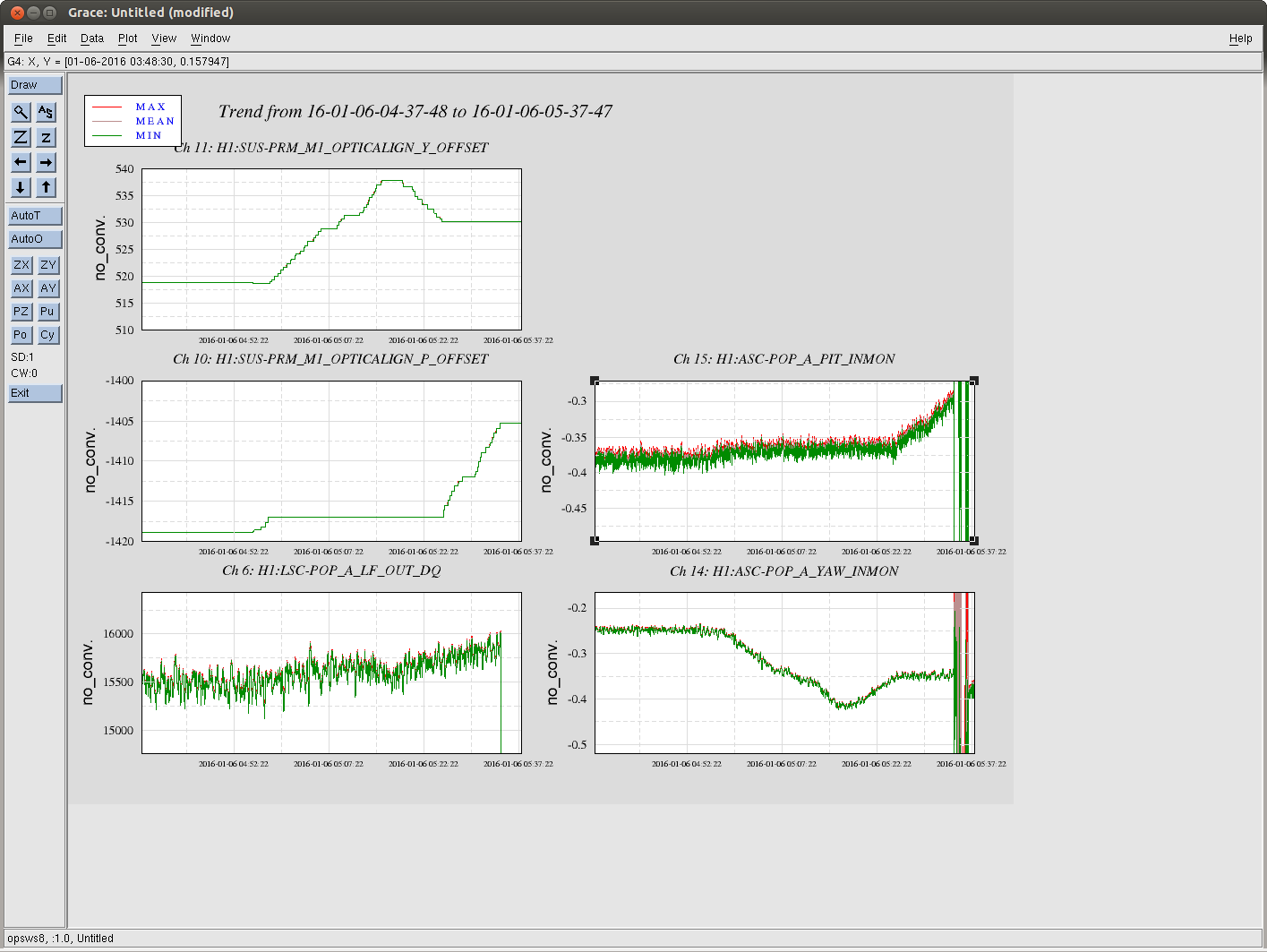
Tonight we had one OK lock with the offsets as Jenne aloged above, which we lost because of an EQ (see Cheryl's shift summary). On relocking without changing the offsets or doing anything special, we lost lock due to the CSOFT pitch instability that has plauged us when we have changed the TMS QPD offsets in the past. (There was a small EQ that arrived on site shortly after this lockloss, but clearly we lost lock because of the pit instability before it arrived). After this, Cheryl and I let the IFO lock and engage ASC with the offsets that Jenne had found this afternoon, then once the soft loops were closed very slowly reverted to the old offsets (see Cheryl's alog) at 2 Watts. Our recycling gain was around 41 when we started, and although it dropped as we reverted the offsets it returned to 41-42 once they were all reverted. We powered up slowly and the recycling gain stayed above 40. After about 20 minutes I thought that things seemed better than they have in several days, so I suggested we offload the full lock ASC. Sadly this broke the lock.
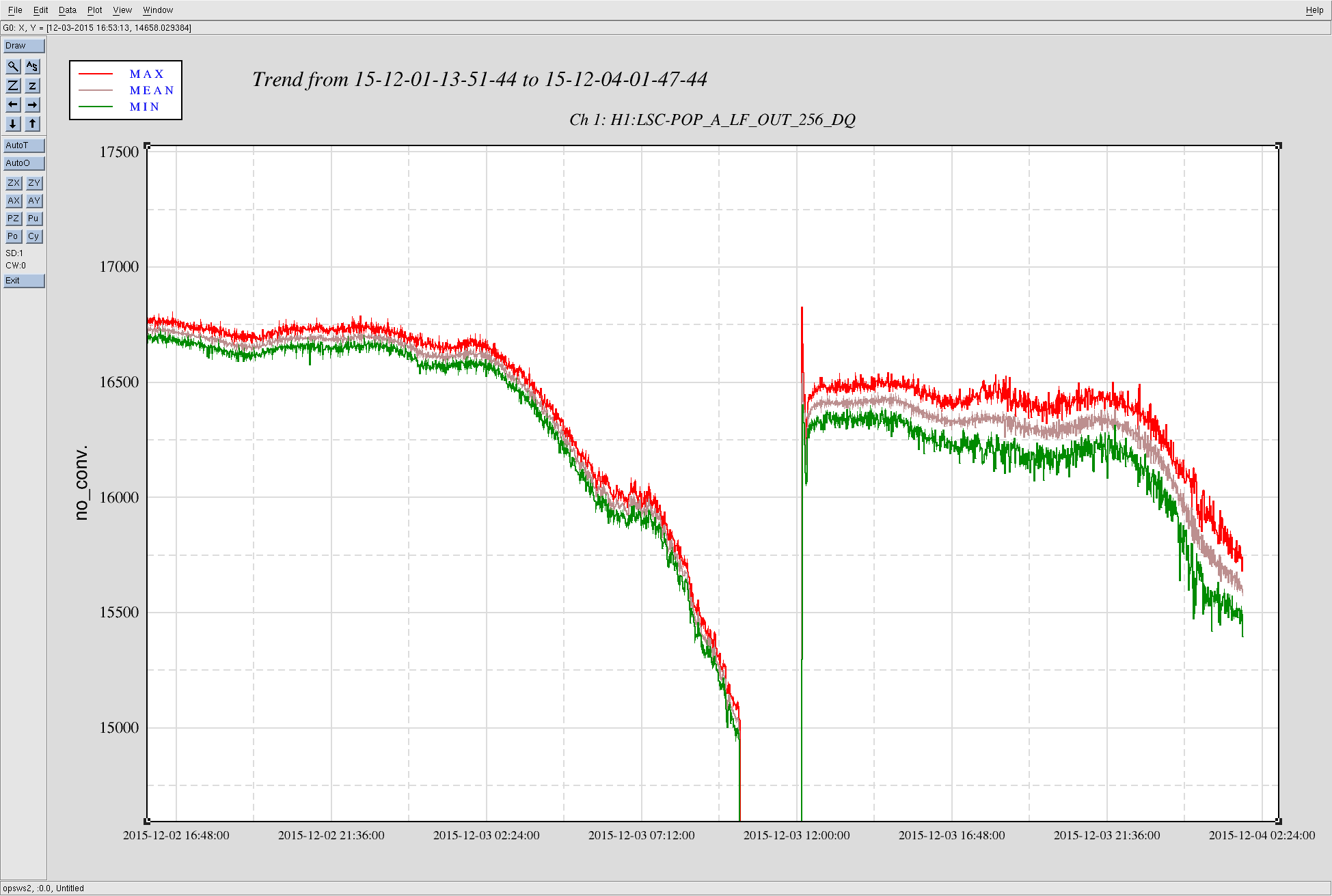
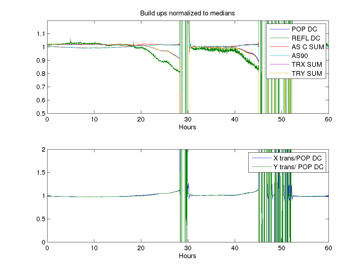
Since this situation is very similar to what happened Dec 3rd -4th, I re-ran the script I used then to look at build ups (23959), for the past 10 days. The results are very similar, the drop off in the POP DC trace is very similar to the drop off in the arm transmissions (ratio of arm transmissions to POP DC is shown in the middle panel, and is changing by at worst 1% while the powers drop by nearly 15%. )
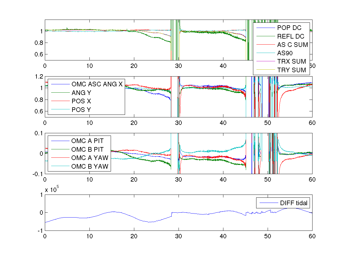
One explanation we considered in December was that the OMC was becoming misaligned, causing the DARM offset to change. The second attachment shows the OMC ASC control signals and the QPDs, which are out of loop. You can see that they move around even in locks where the recycling gain is stable and don't seem to be any worse in the last few days, so it seems like this is not our problem.
Jim has just relocked with a recycling gain of 41, which has been stable for nearly 20 minutes, so this is looking more promising. One thing that we did is edit lscparams so that the guardian will go to 10 Watts in the increase power state instead of the normal set point of 23 W.
Until this is reverted the steps to follow for power up are:
1) request INCREASE_POWER (it is important to change the PSL power only in this state, this state automatically takes care of gain scalings for you).
wait until the power reaches approximately 10 watts, and the recycling gain seems stable. We have been waiting a few minutes here to make sure it stays stable, that should not normally be necessary.
2) open the PSL rotation stage medm screen (from site map under IOO on the top right hand side, Rotation Stage).
3) type 23 in the requested power dialog box and hit go to power
4) only once the rotation stage has finished moving is it safe to leave the INCREASE_POWER state.
For the record, I give you another similar example that Nutsinee and I had experienced back in October (alog 22575 and comments). At that time, we conluded that it was due to subopitimal alignment in TMSY.
Opened FRS ticket
Fault Report 4186 - Trouble advancing past Guardian state ENGAGE_ASC_PART2
(This was done as "for-real" practice with R. Oram)