Title: 1/3 Eve Shift 0:00-8:00 UTC (16:00-24:00 PST). All times in UTC.
State of H1: Observing
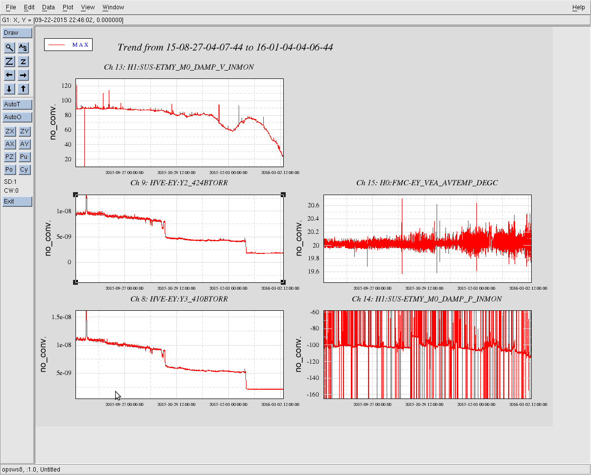
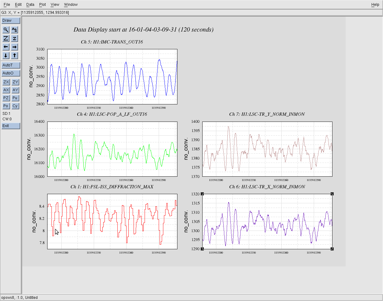
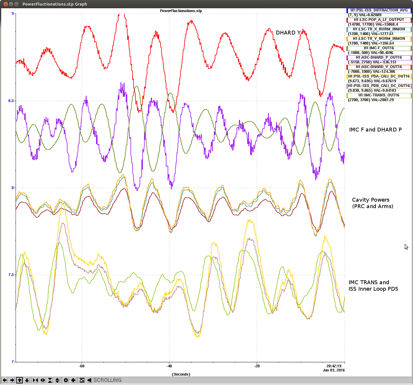
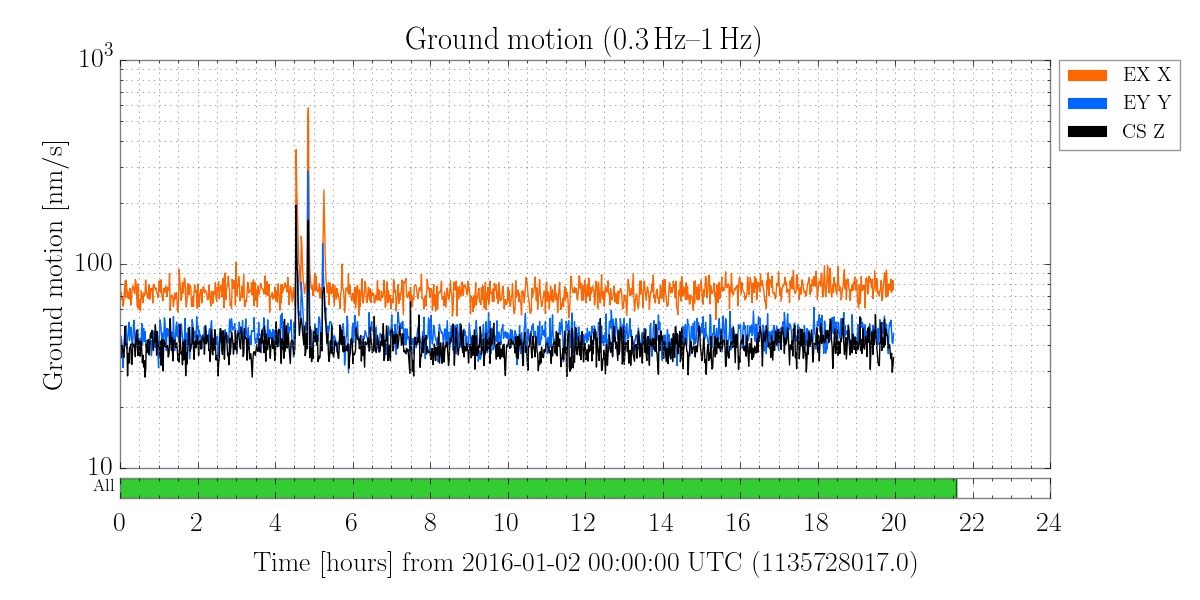
Shift Summary: Started the shift with an unlocked IFO due to EQ. After EQ ringdown, aligned and locked IFO. Since going to Observing, we have been watching the slow degradation of power via POP_A_LF, much like last EVE. At one point we attempted to reverse the trend by adjusting ETMy pitch, but were thwarted by WFS control loops.
Incoming operator: Jim
Activity log:
0:33 Vinny +1 to LVEA and Betsy to Optics Lab
1:08 Vinny +1 out
1:22 Adjusted ALS fiber polarization for both X and Y
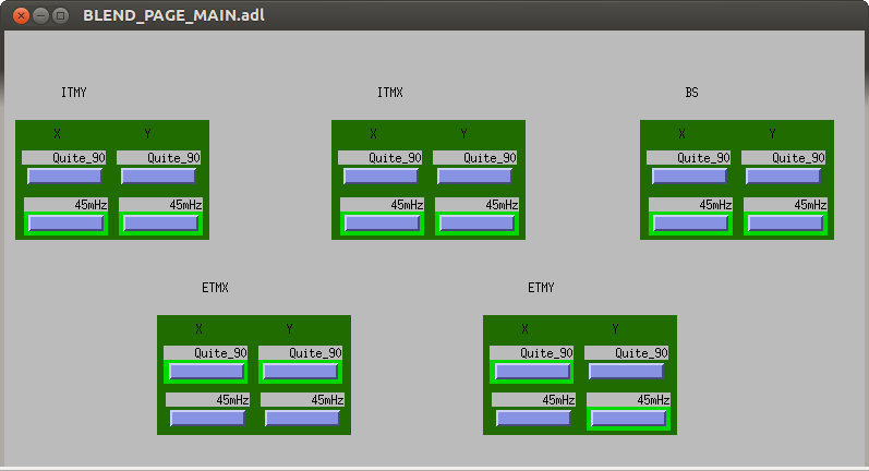
1:27 Switched ETMx ISI X blend to 90 to stop an oscillation and began initial alignment
1:29 Gerardo to CP3
1:30 Betsy out
1:46 Betsy to LVEA for cables
1:56 Gerardo done
2:00 Betsy out
2:50 Observing
6:28 Commissioning mode to adjust ETMy pitch in attempt to save lock
6:40 Back to Observe
7:16 H1:FMC-CS_LVEA_REHEAT_4_DEGF alarm