Happy New Year all!
H1 has historically not has as bad of RF beat / whistle problems as L1 has. In fact, the last alog report is for data on October 30th. But dec 31st shows a high density of glitches above 100Hz and densest above 500Hz, which have the signature shape of RF beats we've seen before and are correlated with PRCL and SRCL, similar to one of the manifestations of whistles seen at LLO.
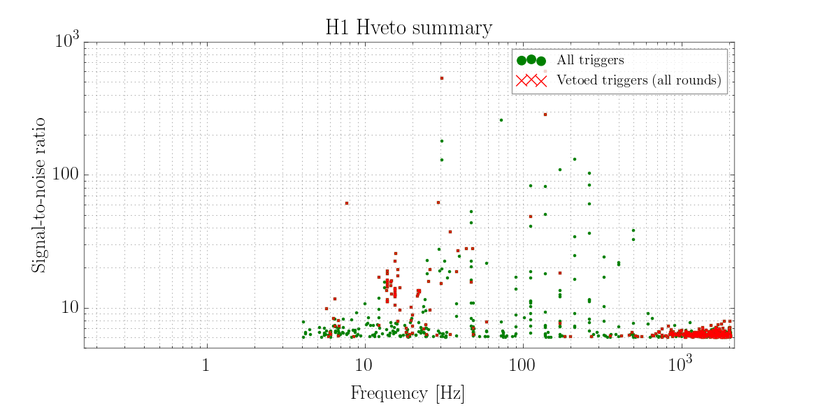
- Figure 1 shows the SNR vs frequency of the glitches at H1 for December 31st. The low-SNR red triggers above 100Hz are mostly whistles that hveto found correlated to PRCL and SRCL.
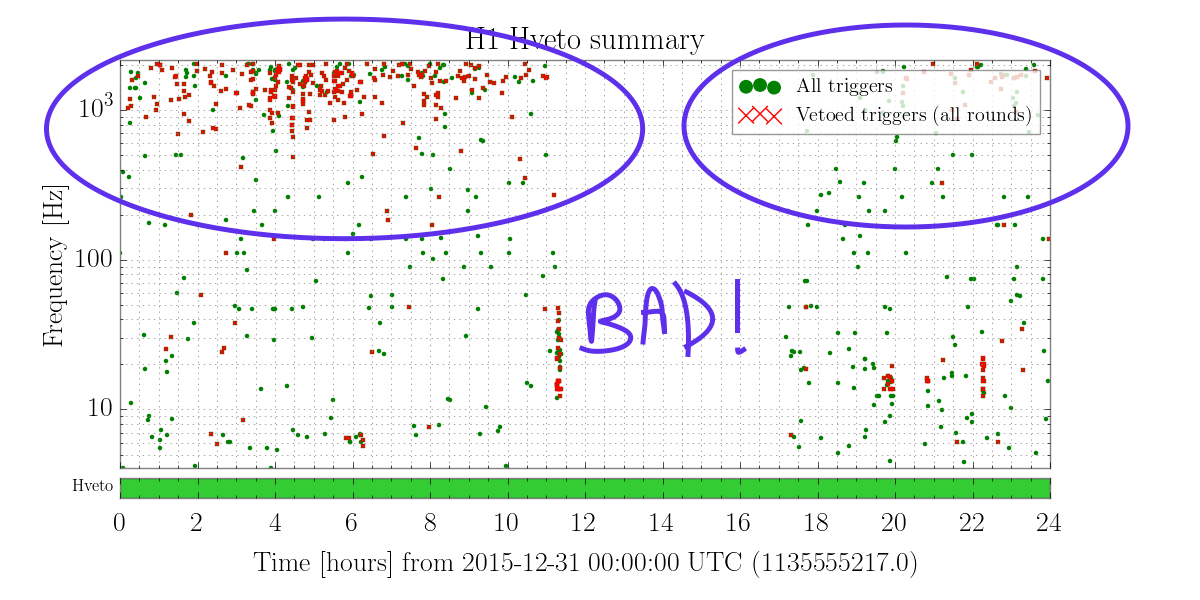
- Figure 5 shows the time-frequency behavior, where I circled the red dots that include whistles, where one can see how many of these quiet whistles were happening on Dec 31.
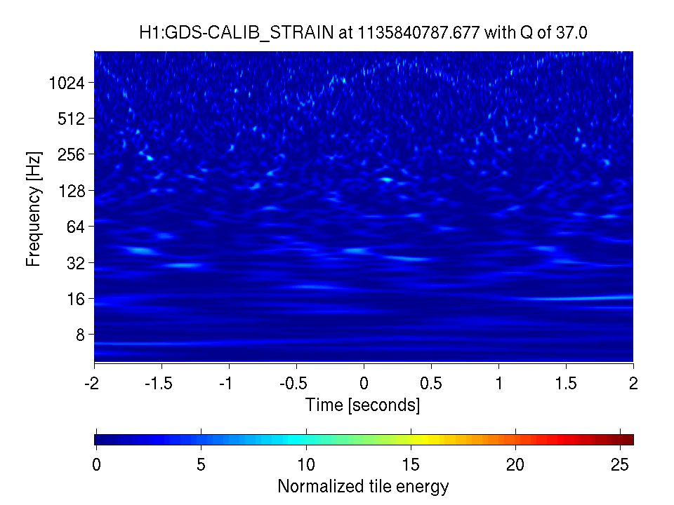
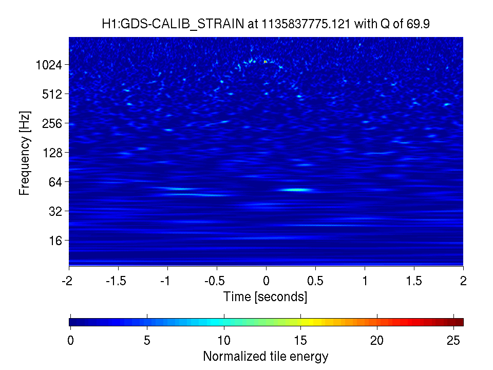
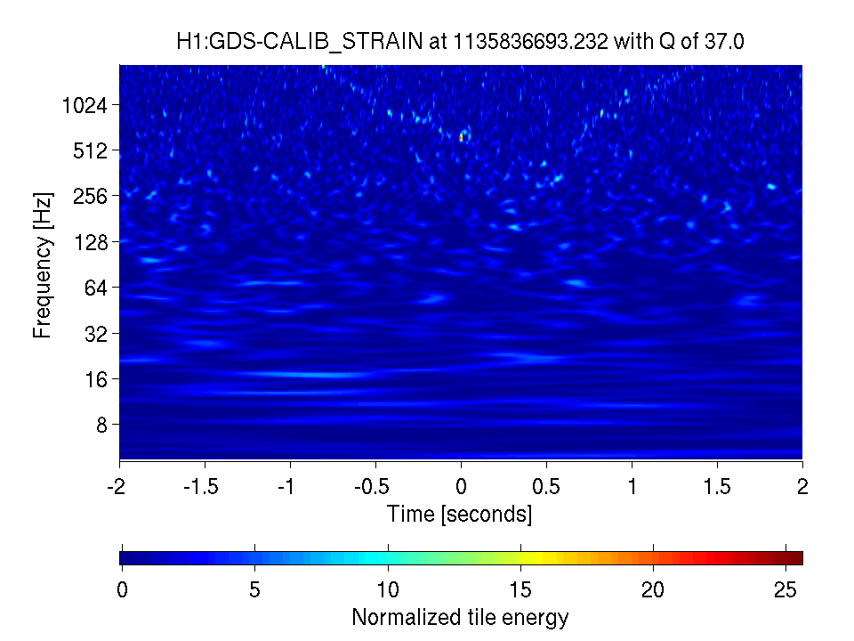
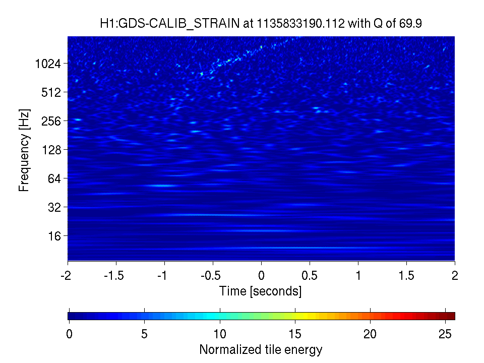
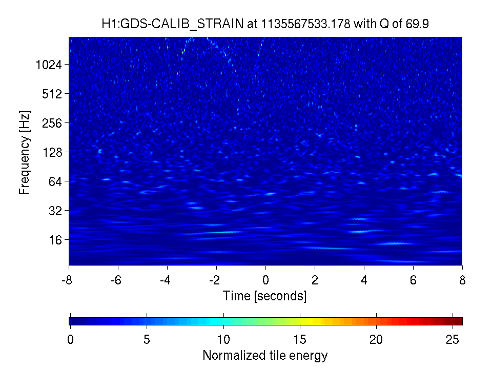
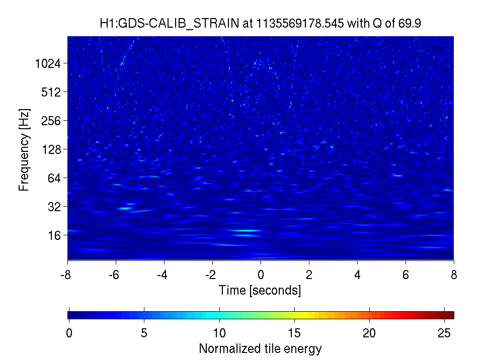
- Figures 2,3,4 show example omega scans of these low-SNR whistles. Note that these extend to low enough frequency to reach the CBC signal range.
Note 1: we produce auto omega scans for the loudest glitches that hveto finds, and these whistles are all very quiet. If anyone wants to follow these up in more detail, you can get GPS times for the high-frequency low-snr triggers for Dec 31 correlations with PRCL and SRCL at those links.
Note 2: Dec 31 looks like the worst day, but there might have been some weak whistles occuring on other days too, but we'd have to follow up some low SNR triggers on those days (e.g. today Jan 1 and the past few days).

Quick update: RF beat / whistles are still happening today, Jan 3. The hveto page shows whistles in rounds 4 and 8 coincident this time with H1:ASC-REFL_B_RF45_Q_PIT_OUT_DQ (and not PRCL and SRCL as above, so a different line/VCO freq must be at play). They are still low SNR, but lightly visible in omega scans. Some example omega scans are attached and linked here. Text files of glitches coincident with ASC REFL B RF45 are here for round 4 and round 8.