cheryl.vorvick@LIGO.ORG - posted 13:50, Monday 28 December 2015 (24518)
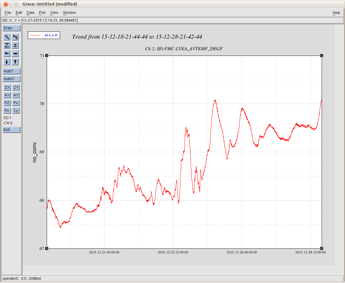
LVEA temperature is high - alarm came in at 20:45UTC - plot attached shows 10 days
- LVEA temperature crossed 70 degrees F.
- Temperature appears to be leveling off at 70.1F.
- 10 day trend shows overall increase.
- LVEA temperature crossed 70F on 12/25, and returned to a temperature below the alarm level in about 2 hours.
Images attached to this report