I'm testing a new commissioning reservation system I wrote this afternoon using python. This is a file based system replacing the old EPICS system. The main reason for the change is that the old EPICS system developed problems related to updates and required a lot of maintenance. It was also awkward to configure and restrictive in what it could do.
The reservation file is /opt/rtcds/lho/h1/cds/reservations.txt
There are three python scripts:
make_reservation.py is available to all users, it allows you to create your reservation
display_reservations.py script loops every second and shows the currently open reservations
decrement_reservations.py script is ran as a cronjob every minute, it decrements the time-to-live of each reservation and deletes them when they expire.
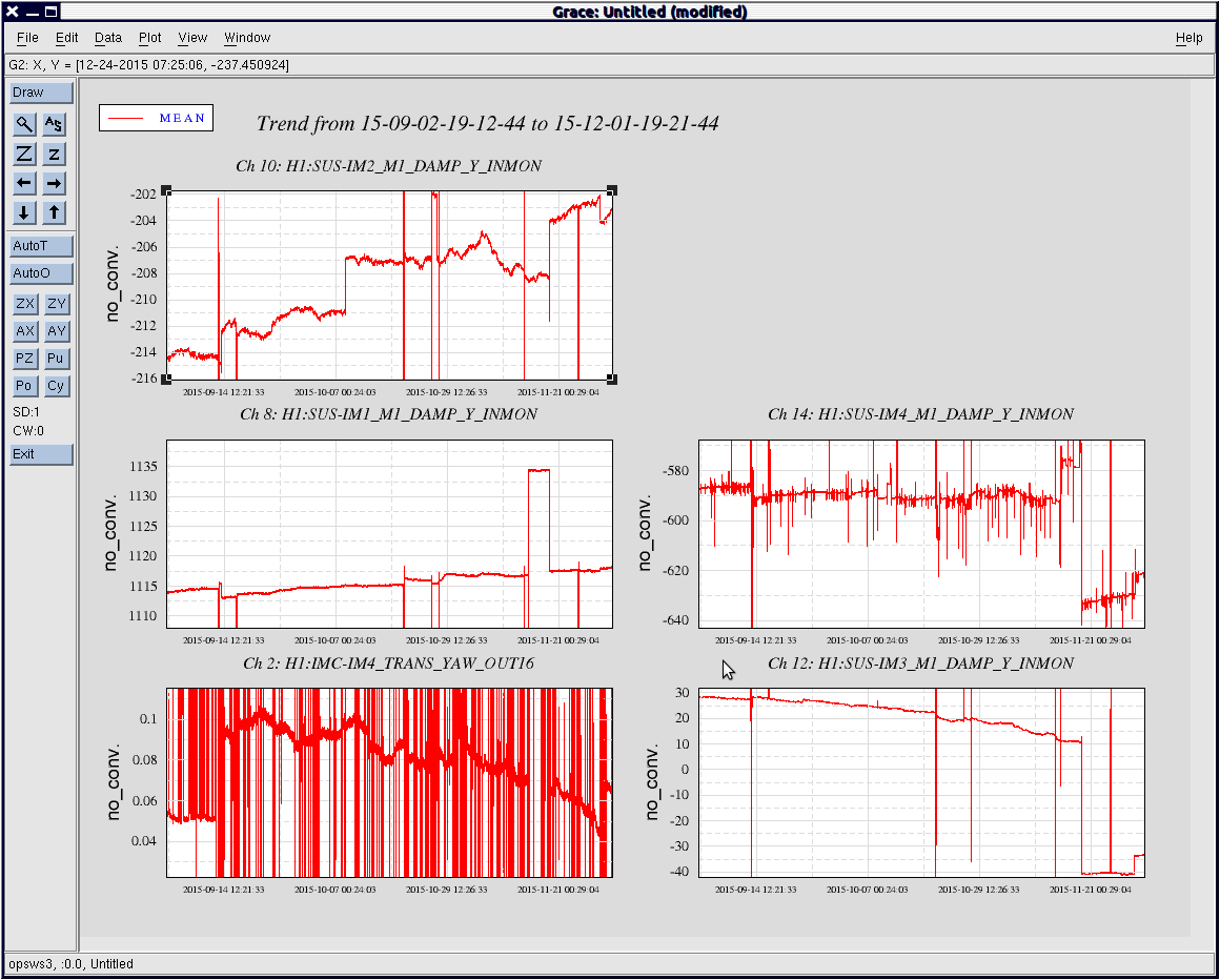
I have a display running on the left control room TV closest to the projector screen.
Here is the usage document for the make_reservation.py script
controls@opsws6:~ 0$ make_reservation.py -h
usage: make_reservation.py [-h] system name task contact length
create a reservation for a system
positional arguments:
system the system you are reserving, e.g. model/daq
name your name
task description of your task
contact your contact info (location, phone num)
length length of time (d:hh:mm)
optional arguments:
-h, --help show this help message and exit
If you need to use spaces, surround the string with quotes. There are no limitations on string contents. Here is an example reservation
make_reservation.py "PEM and DAQ" david.barker "update PEM models, restart DAQ" "phone 255" 0:2:0