ryan.short@LIGO.ORG - posted 10:34, Monday 05 May 2025 (84253)
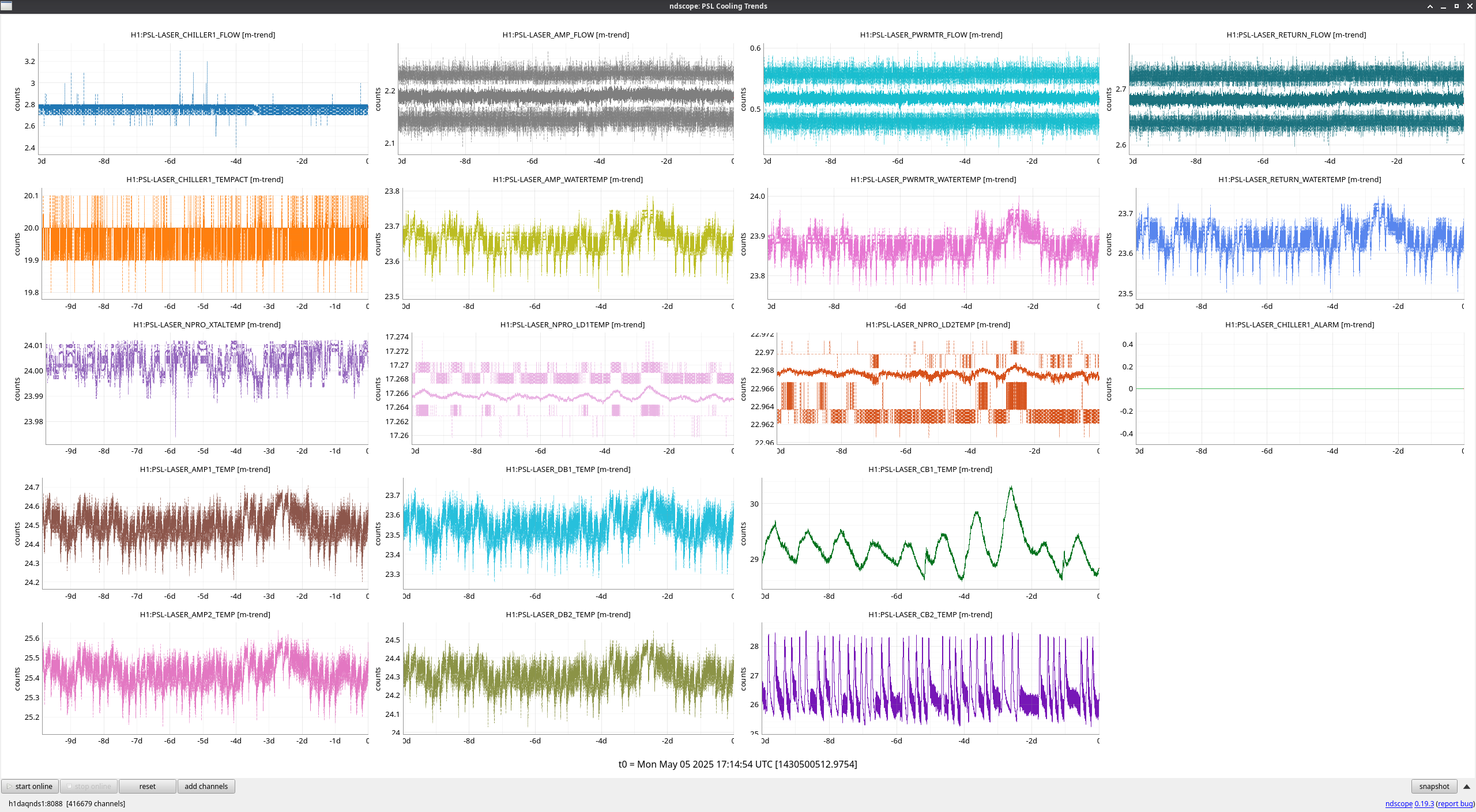
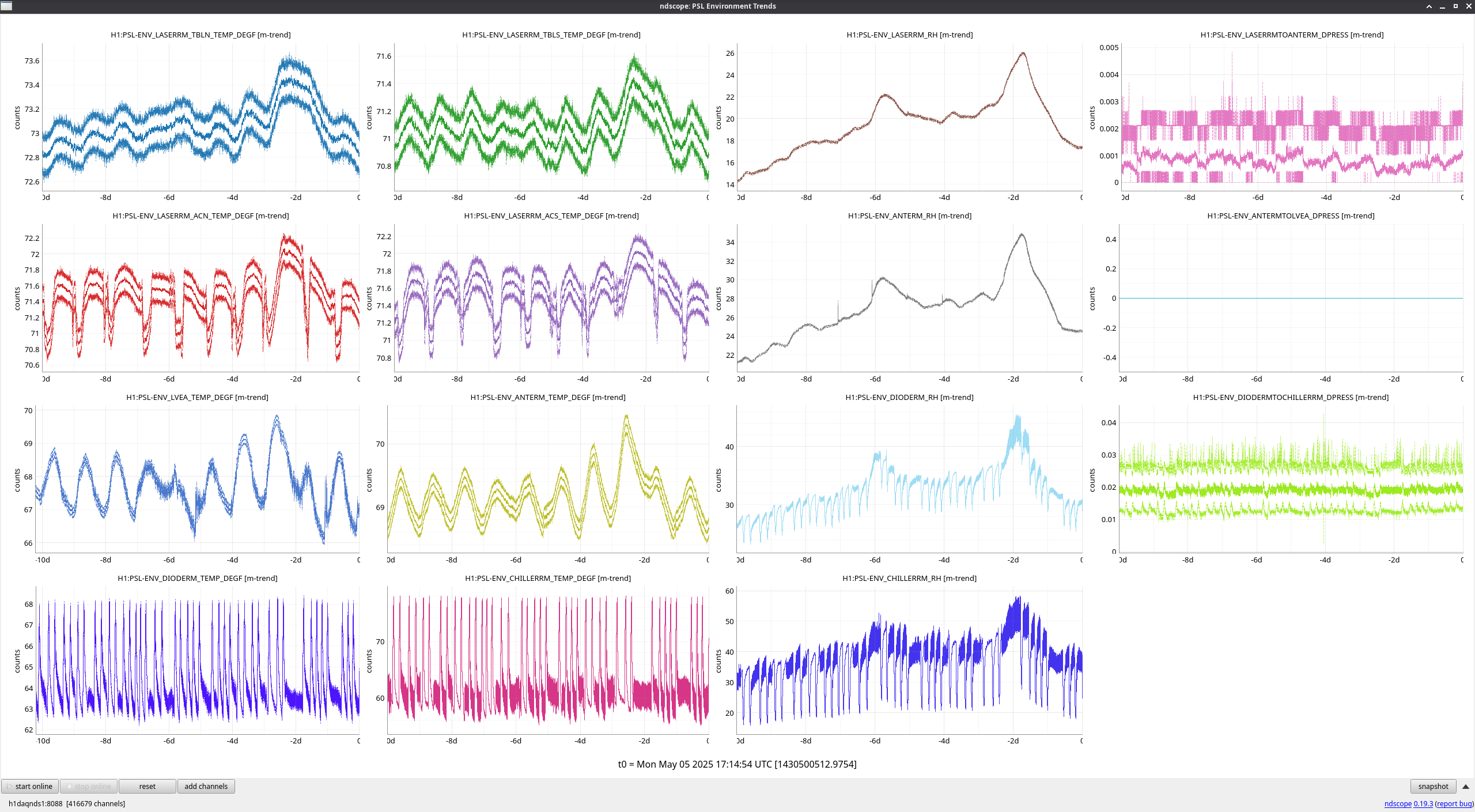
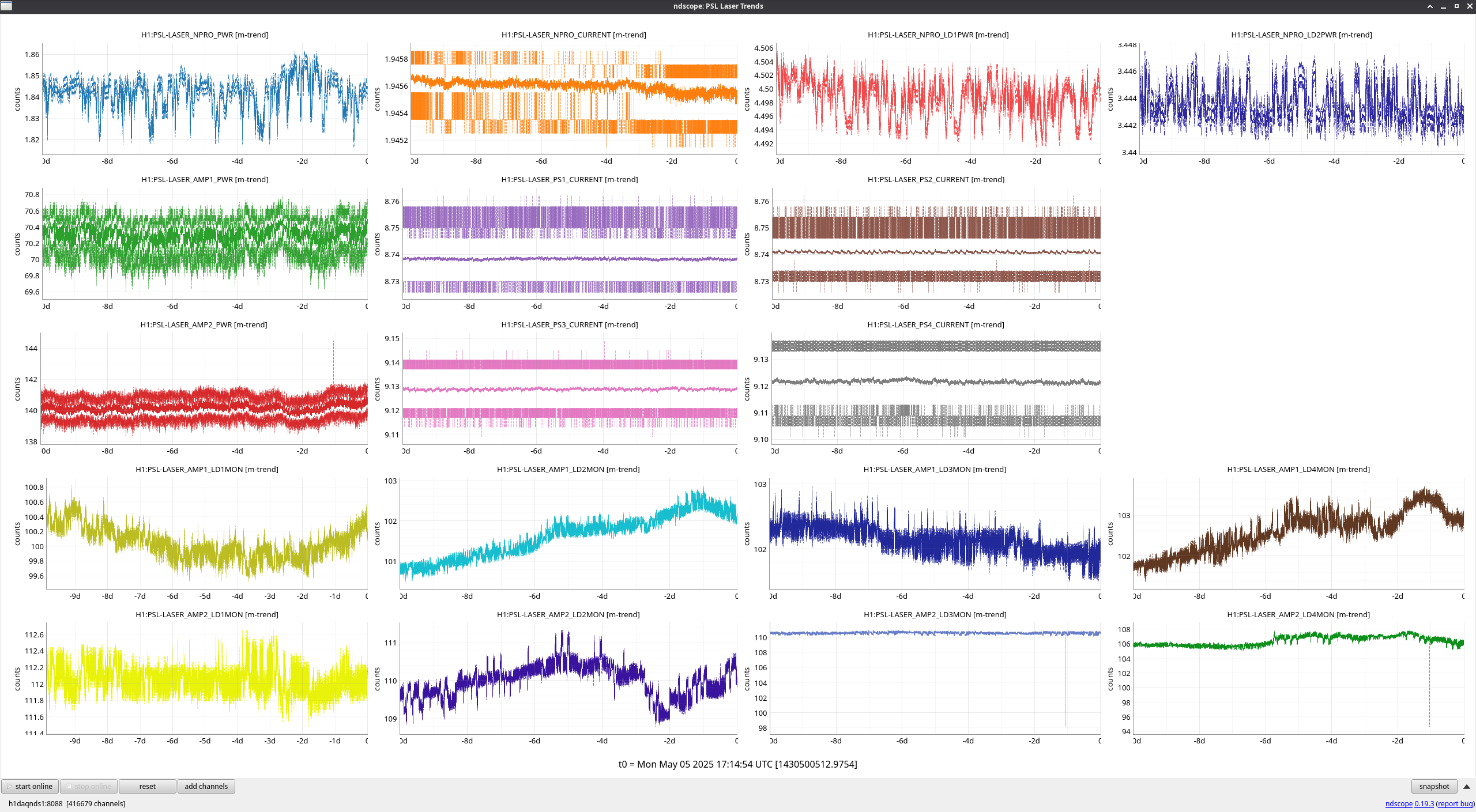
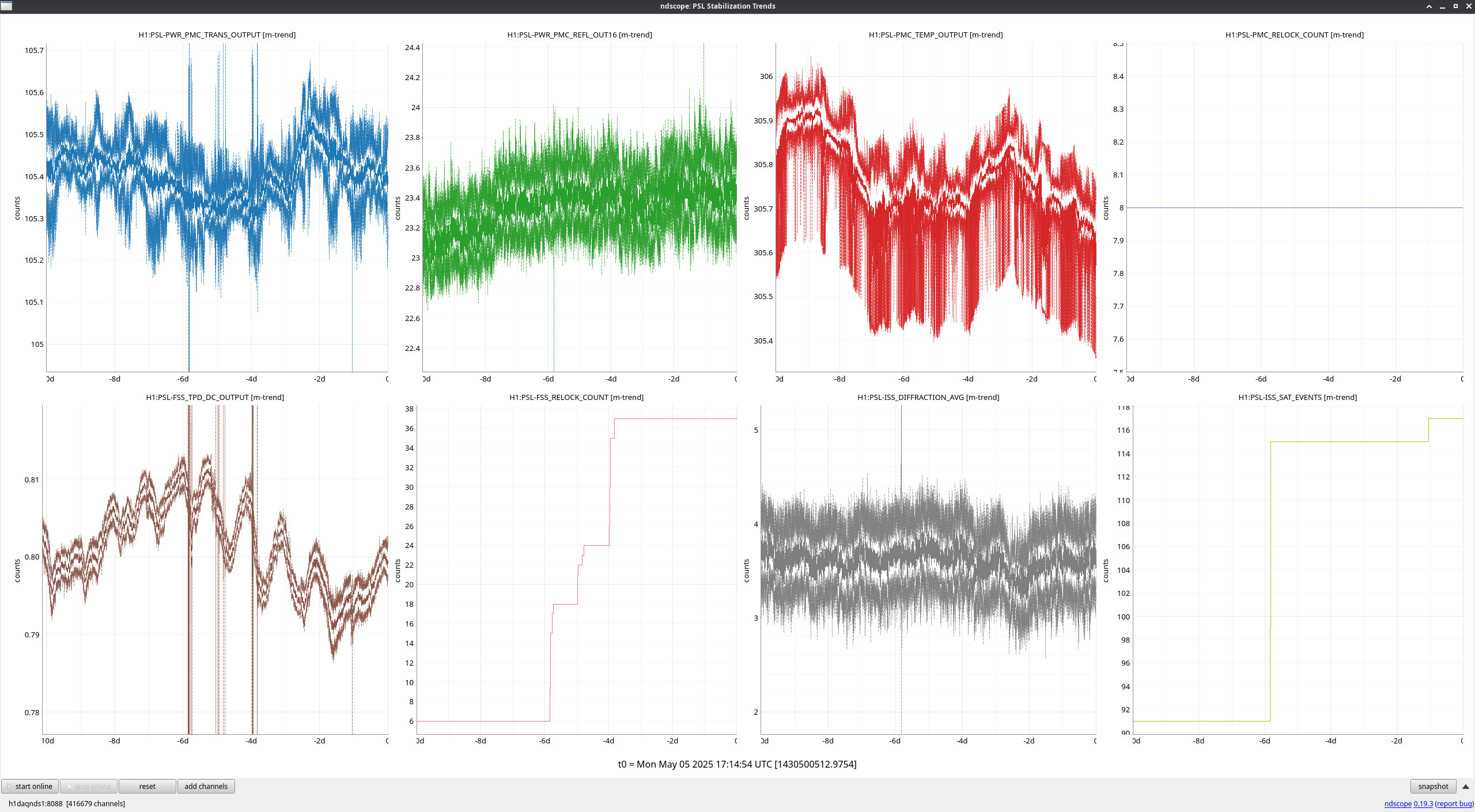
PSL 10-Day Trends
FAMIS 31084
No major events of note this week.
Images attached to this report
FAMIS 31084
No major events of note this week.
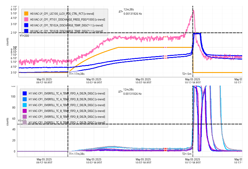
Mon May 05 10:12:38 2025 INFO: Fill completed in 12min 34secs
Dry air skid checks, water pump, kobelco, drying towers all nominal.
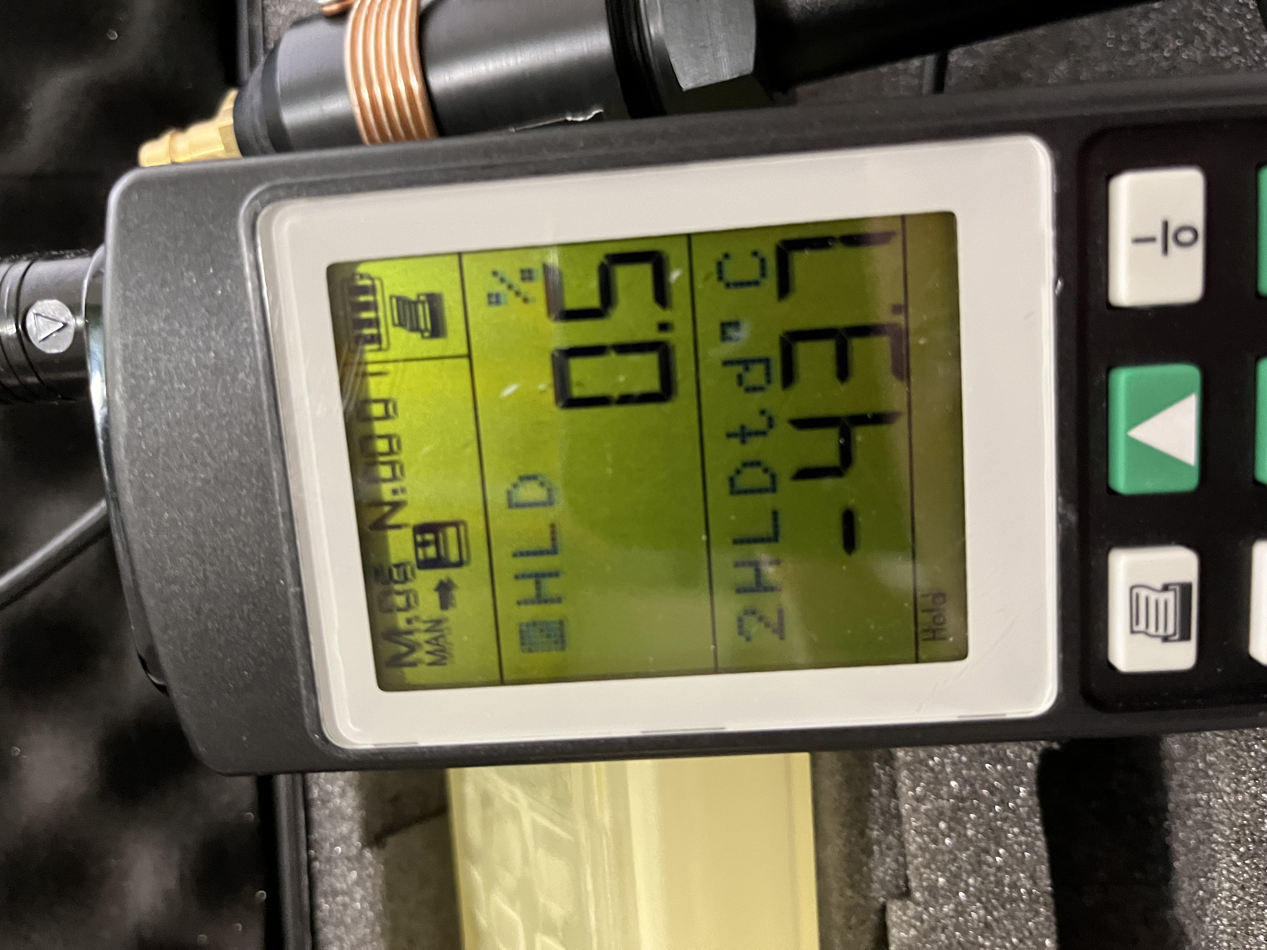
Dew point measurement at HAM1 -43.7 °C.
.
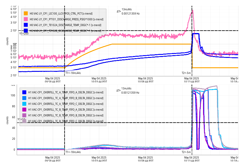
Sun May 04 10:13:44 2025 INFO: Fill completed in 13min 40secs
Late entry for yesterday's fill.
TITLE: 05/05 Day Shift: 1430-2330 UTC (0730-1630 PST), all times posted in UTC
STATE of H1: Planned Engineering
OUTGOING OPERATOR: None
CURRENT ENVIRONMENT:
SEI_ENV state: MAINTENANCE
Wind: 4mph Gusts, 1mph 3min avg
Primary useism: 0.03 μm/s
Secondary useism: 0.12 μm/s
QUICK SUMMARY: Vent work continues this week with ongoing alignment/profiling in HAM1 and work on the EY wind fence.
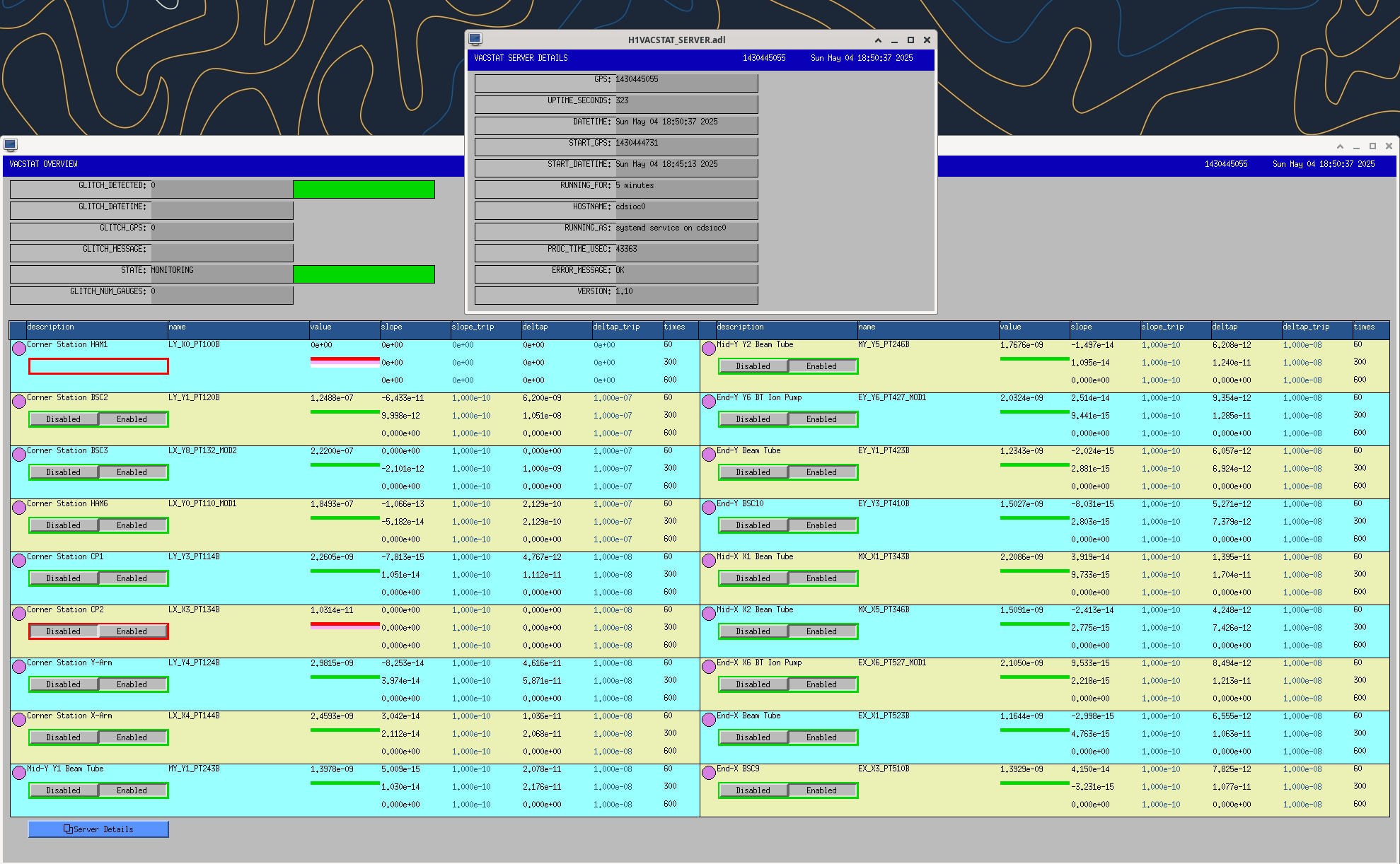
Following the vacuum issue this morning, the vacuum gauges for BSC2, BSC3 and HAM6 have been added back to VACSTAT. These gauges, plus HAM1, had been removed from VACSTAT at the beginning of the vent on 02apr2025. A temporary IOC vacstat_dummy_ioc.py had been running to serve the missing channels to the EDC.
This evening I added BSC2, BSC3, HAM6 back to vacstat's prod.yaml and restarted the service. I then removed these from vacstat_dummy_ioc.py (it now only simulates HAM1).
I re-enabled the VACSTAT multiple gauge alarm to the vacuum team in the alarms system, which was restarted at 18:34.
After the vacstat restart we quickly got a delta-p alarm for BSC2 because it still had the default sensitivity of 1e-08 but the vertex is currently running in the 1e-07Torr range. The sensitivities for BSC2,3 and HAM6 were reduced to deltap=1e-07 and vacstat was restarted.
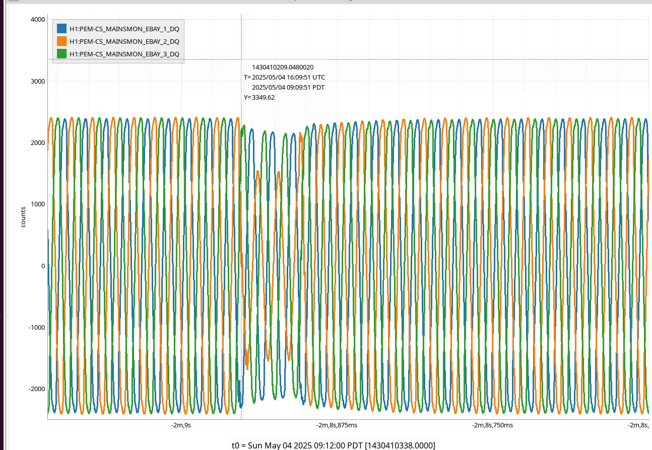
We had a power glitch 09:09:51 Sun 04may2025 PDT.
GC OSB UPS:
Time : 08:09:51
Code : 0x0109
Warning - UPS: On battery power in response to an input power problem.
Time : 08:10:11
Code : 0x0210
Informational - UPS: An input voltage or frequency problem no longer prevents switching to bypass mode.
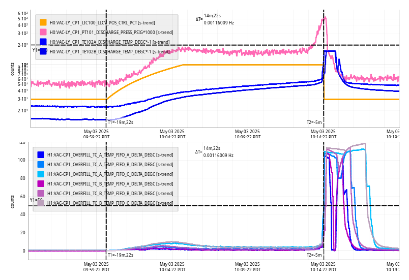
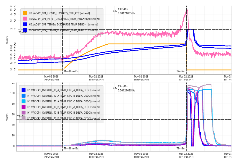
Today morning I checked the pressures, and they were suspiciously high. After refreshing the screenshots a few times, it was evident that we lost pumping power.
After arriving at the site, I immediately saw that all the 3 major turbo stations were tripped. In detail, the XBM and the OMC turbo stations were completely tripped (big and small backing turbos, scroll pumps tripped, all safety valves closed). At YBM only the main turbo was tripped, and only the main safety valve was closed.
The first trip happened at ~9:10 am this morning, and the other 2 between 9:10 and 9:20 am, roughly.

I closed the big gate valves, checked the crush bearings (all were 100%), restarted all the stations, and now they are all valved back in.
Sat May 03 10:14:22 2025 INFO: Fill completed in 14min 18secs
LAB DUST-1 failed again at 05:44:06 Sat 03may2025 causing the EDC is disconnect from 32 channels.
Prior to the IOC crashing, there was a 10 minute stretch between 02:35 and 02:46 where the particle count was over 5000, it was below 100 at all other times.
I've restarted the DUST-LAB IOC to green up the EDC. If this continues I could simulate this IOC until Ryan can investigate.
Good news:
One of the RF cables for ASC-WFS_B, the one on the right viewed from the front where the diode sits, started working after I disconnected and reconnected the cable. Marc and Daniel can see the connection from outside using their tdr setup.
Bad news:
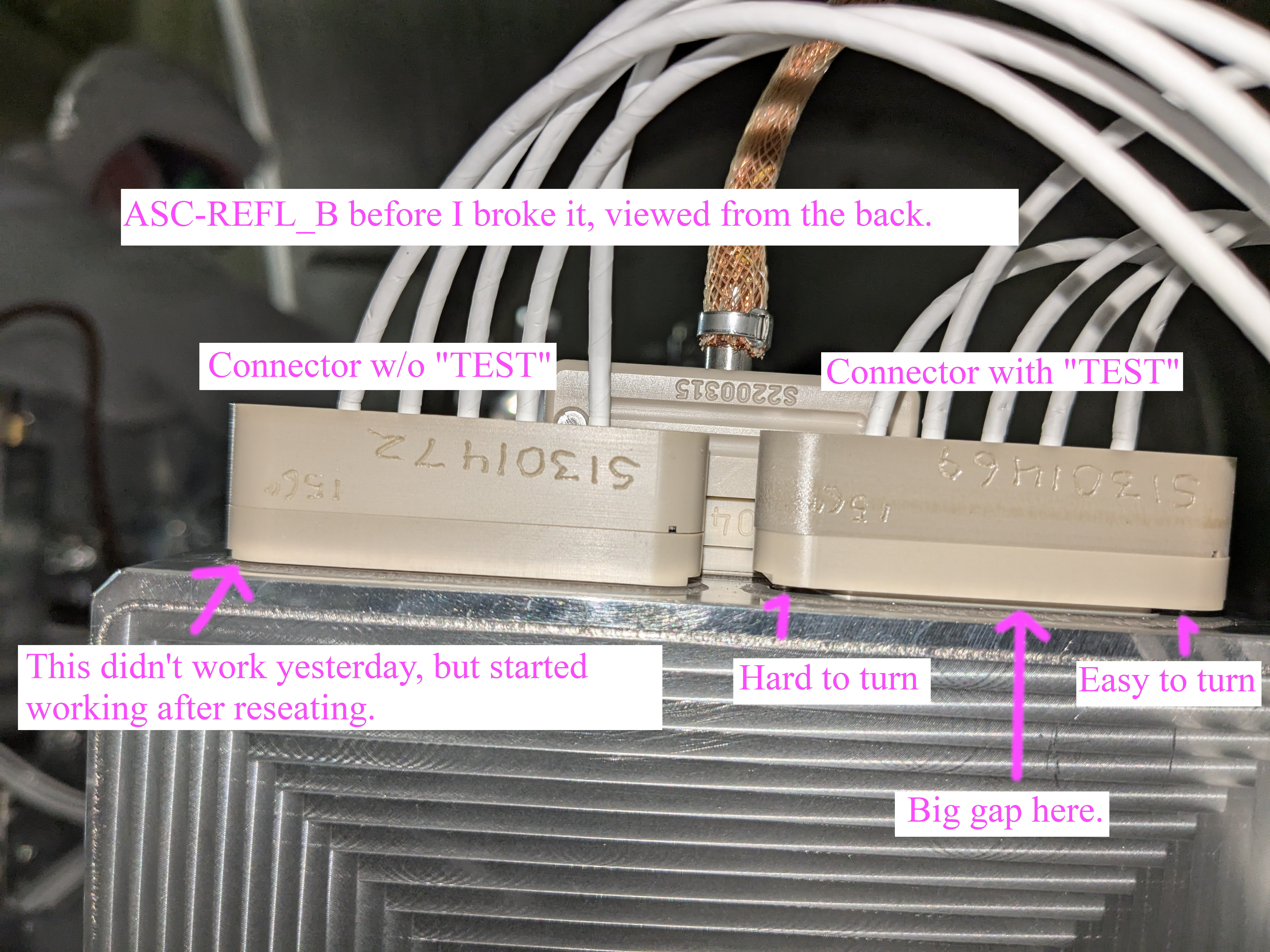
I broke one of two RF connectors per WFS for both ASC-REFL_A and ASC-REFL_B in somewhat different ways. For both of them, the broken one is the one with "TEST" input. Viewed from the front of the WFS, it's on the left.
Instead of one fully working WFS and one totally broken WFS, we now have two units of half-working WFS. We need a help from somebody who has some experience dealing with helicoils.
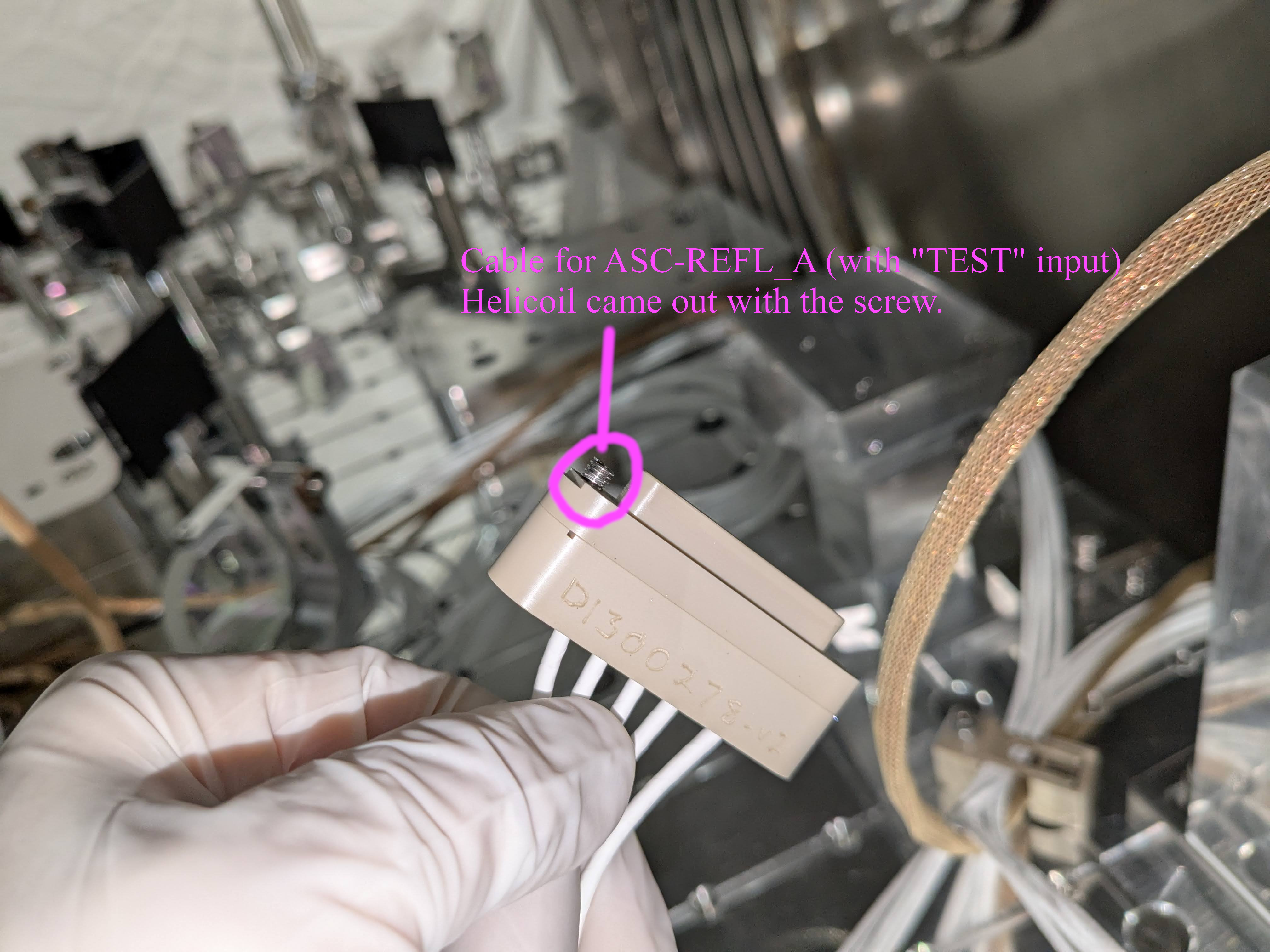
ASC-REFL_A
Helicoil insert of one of the RF connector screws was stuck with the screw and came out with the cable-side connector (1st picture). I'll try to remove the helicoil from the screw later, but even if I'm successful we must install a new helicoil into the WFS, and reconnect the cable.
(Added later: I quickly pinched the helicoil using a class B needle noise plier and tried to "unscrew" the screw from helicoil but wasn't successful. I felt as if a bit more of the "free" helicoil emerged from the tip of the screw, it eventually was crushed by the plier and came off (4th pic), maybe it takes more time or maybe it galled, but I stopped there as I was worried to damage the thread of the screw.)
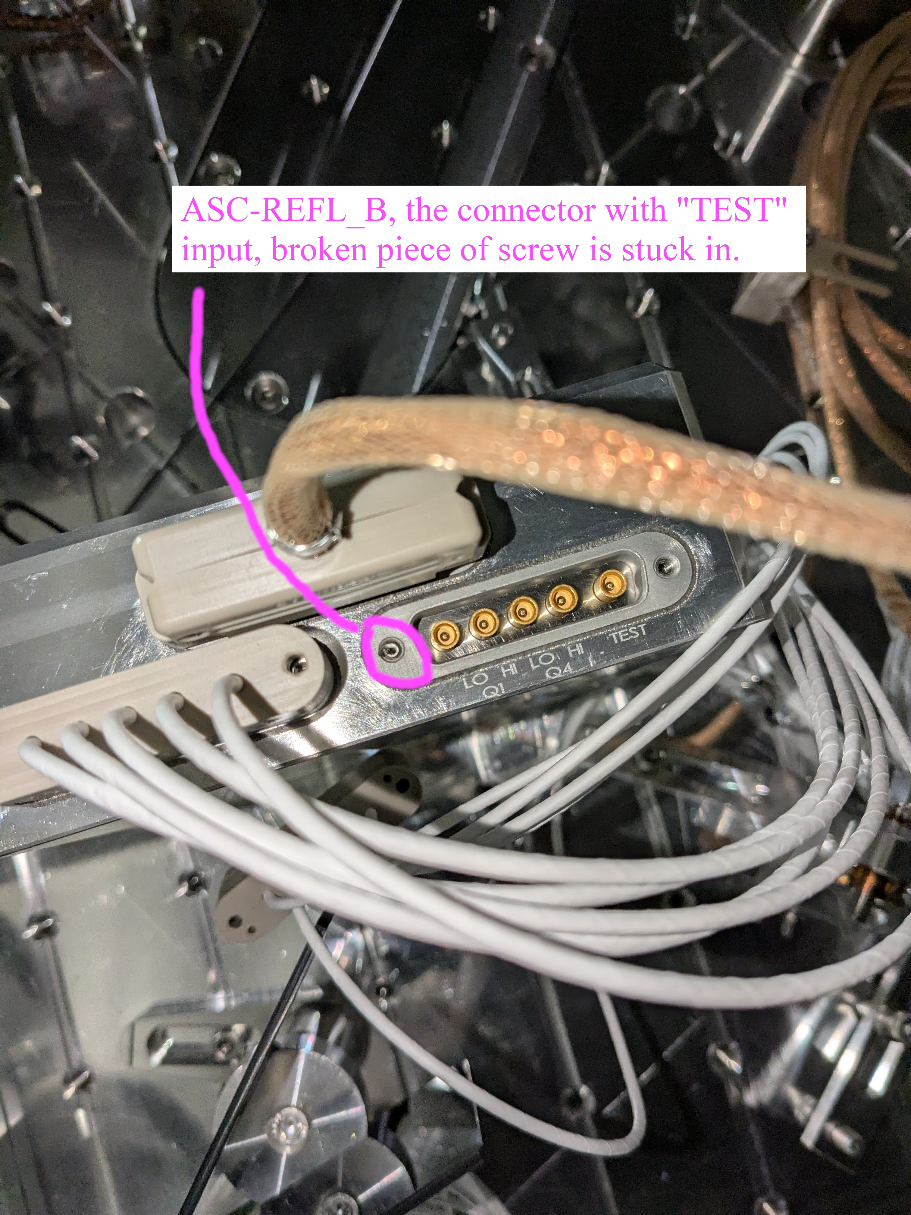
ASC-REFL_B
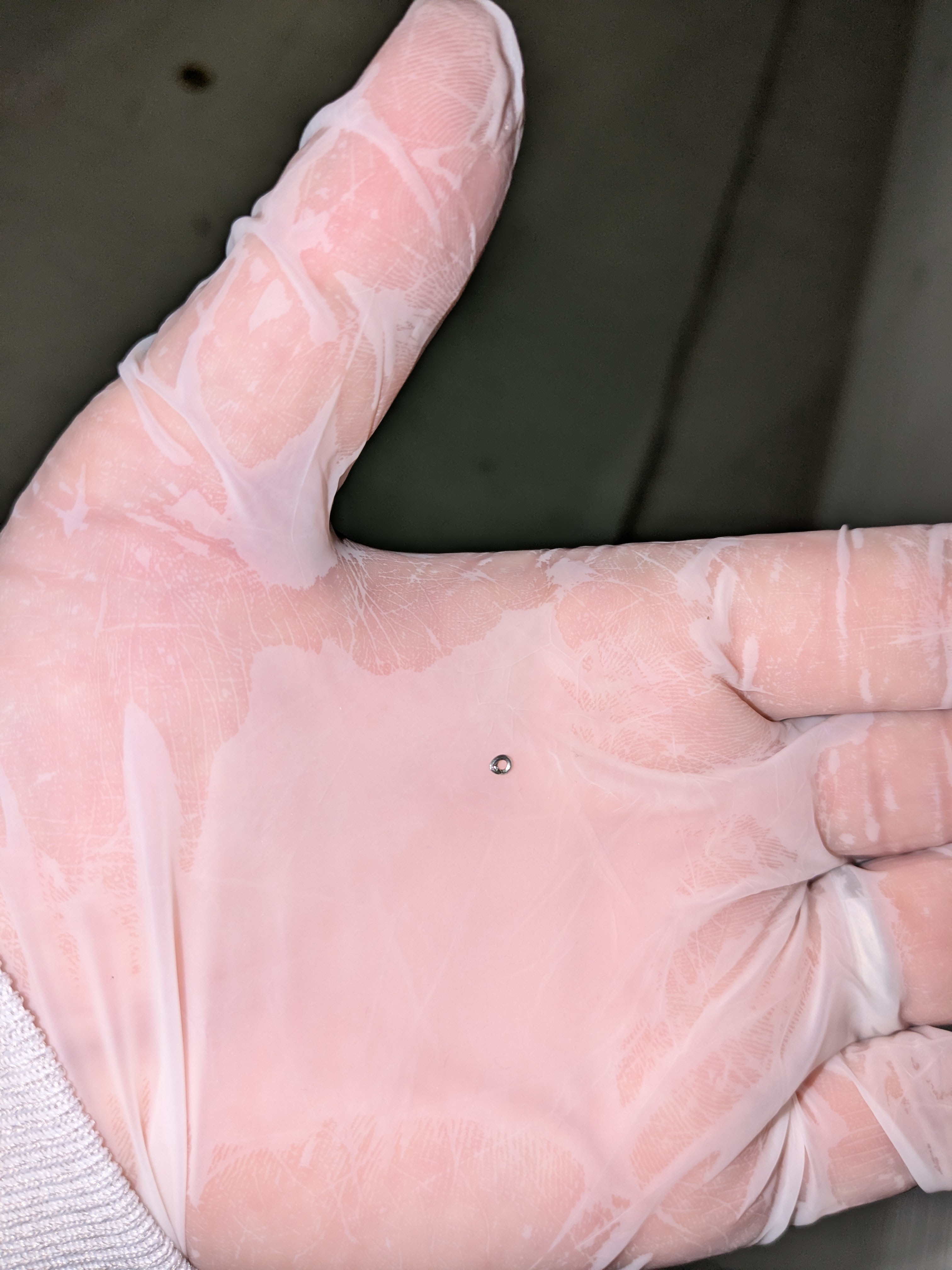
One of the RF connector screws was broken, and the broken bit stayed inside the connector on the WFS (2nd attachment). The screw seems to be vented. If we have a small screw extractor bit, we might be able to remove that.
Not sure about the cable-side connector. If we can disassemble and replace the screw with a new one, that will be good.
How this happened:
Yesterday, Daniel found that none of RF of ASC-REFL_B was not working at all. alog 84224
Today I disconnected one of RF cables (on the right viewed from the front) on ASC-REFL_B and reconnected. Eventually it turns out that that fixed the issue for that cable, but at the time we somehow confused ourselves and started to think that WFSA in chamber was WFSB in RF world and vice versa.
Then I disconnected both of the cables on ASC-REFL_A and swapped the positions so that left is right and vice versa (because we thought that it was REFL_B), and Daniel found that the RF signals were swapped for REFL_A. Fine, no more confusion.
I removed the cables from ASC-REFL_A again and started putting them back in a correct order. However, as soon as I started working on the first cable, the one on with "TEST" input, I felt that one of the screws was stuck even though the connector was not yet fully seated. I backed it off and found that the helicoil was stuck with the screw.
Since there was no immediate remedy for this, I started working on ASC-REFL_B. Turned out that the cable I reseated was working fine. I looked at the connectors from the back (3rd picture) and the non-working one didn't look as if it was fully seated. One of the screws was easy to tighten, but the other was not. I tried to tighten them while maintaining balance (tighten one screw a bit, the other a bit, check that the connector gap is uniform, repeat), but the harder-to-turn one broke before the connector was fully seated.
In the third picture you can clearly see a gap between two mating surfaces for the connector on the right on the picture, and that's the one that shows/showed no sign of connection anywhere. Unfortunately I don't have a picture before I reseated the first connector (on the left on the picture), so I don't know if that one also had a gap before, but I strongly suspect that it did.
Note about the 5-way SMP connector
SMP (Sub Miniature Push-on) connector itself is a snap-on connector. You need a substantial pushing force to make it snap on at the last 0.5mm or so of insertion travel. Once it snaps on, no external force is necessary to retain the connection, but you need to first make it snap.
5-way SMP we're using is just 5 single SMP put in a bigger connector shell with two connection screws. Unlike the single SMP, it's not possible to make it snap by just using your fingers because the entire connector slides in and out with the screws.
However, if screws are completely removed, it might be possible for somebody to fully insert the connector by just using fingers at least in principle. The problem is the force needed for that. Even a single SMP needs some serious pushing, at least that's the case for SMP used in ISS array, but we have five SMPs in a single cable/connector, so the person must have VERY strong fingers.
TITLE: 05/02 Day Shift: 1430-2330 UTC (0730-1630 PST), all times posted in UTC
STATE of H1: Planned Engineering
INCOMING OPERATOR: None
SHIFT SUMMARY: Lots of earthquakes today from off the coast of southern Argentina, 7.4, 6.4, 6.6, and lots of 5s and 4s. Jim and I brought the CS BSCs to isolated alog84235. Zone5 is getting a touch warm but it still within its recent range of fluxuations as of 23:30UTC(FMCS).
LOG:
| Start Time | System | Name | Location | Lazer_Haz | Task | Time End |
|---|---|---|---|---|---|---|
| 15:12 | FAC | Randy, Mitch, Jim, Corey | EndY | N | Wind fence work | 19:33 |
| 15:24 | FAC | Kim, Nellie | LVEA | Y | Tech clean | 16:14 |
| 15:25 | VAC | Jordan | LVEA | Y | Purge air checks | 15:42 |
| 16:15 | FAC | Tony, Kim, Nellie | PCAL lab/ Optics lab | N/LOCAL | Tech clean | 16:40 |
| 16:46 | ISC | Keita, Elenna, Jennie | LVEA | Y | HAM1 REFL beam path | 19:00 |
| 17:27 | ISC | Daniel | LVEA | Y | Rack measurements, by PSL/HAM1 | 19:00 |
| 17:27 | EE | Marc | LVEA | Y | Checks | 19:14 |
| 17:10 | OPS | RyanC | LVEA | Y | HAM1 dust monitor check, handhelds | 17:25 |
| 17:42 | VAC | Jordan | MidY | N | CP3 pump check | 18:22 |
| 17:58 | EPO/VAC | Mike + Crew | X1, xarm | N | Tour | 18:41 |
| 18:56 | CAL | Tony | PCAL lab | LOCAL | PCAL work | 19:01 |
| 19:45 | VAC | Janos, Jon, Mike, Marc, Anna | LVEA | Y | Tour for Anna, Marc & Mike out at 20:15 | 21:15 |
| 20:25 | ISC | Jennie | LVEA | Y | Check out the going ons, HAM1 | 20:27 |
| 21:35 | EPO | Mike | LVEA | Y | Virtual tour | 21:48 |
| 22:06 | ISC | Elenna, Jennie | LVEA | Y | HAM1 beam profiling | 23:19 |
| 22:23 | VAC | Jordan | LVEA | Y | CP3 check | 22:52 |
| 22:51 | VAC | Janos | LVEA | Y | Checks | 22:58 |
| 23:21 | CAL | Tony | PCAL lab | Y | Cover up spheres | 23:25 |
The EndY wind fence work DONE
HAM1 beam profiling Ongoing
Fri May 02 10:13:46 2025 INFO: Fill completed in 13min 43secs
TITLE: 05/02 Day Shift: 1430-2330 UTC (0730-1630 PST), all times posted in UTC
STATE of H1: Planned Engineering
OUTGOING OPERATOR: None
CURRENT ENVIRONMENT:
SEI_ENV state: MAINTENANCE
Wind: 6mph Gusts, 4mph 3min avg
Primary useism: 5.26 μm/s
Secondary useism: 0.36 μm/s
QUICK SUMMARY:
Jim and I brought the CS BSC ISIs back to their nominal ISOLATED states, BS, ITMY, and ITMX at Sheila's recommendation, we'll see if we also need/want to bring the HAM ISIs to ISOLATED.
Keita, Elenna, Jennie W.
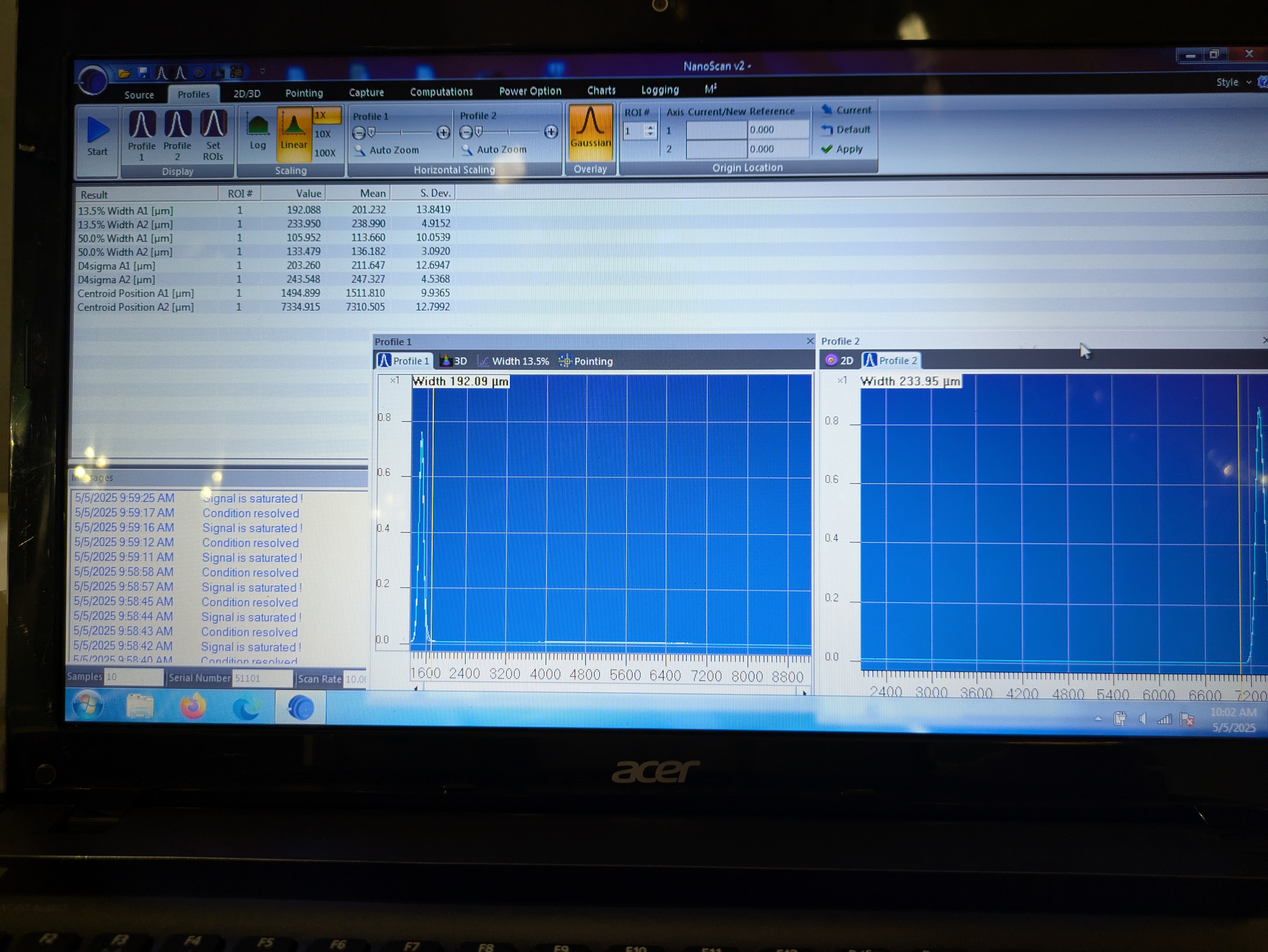
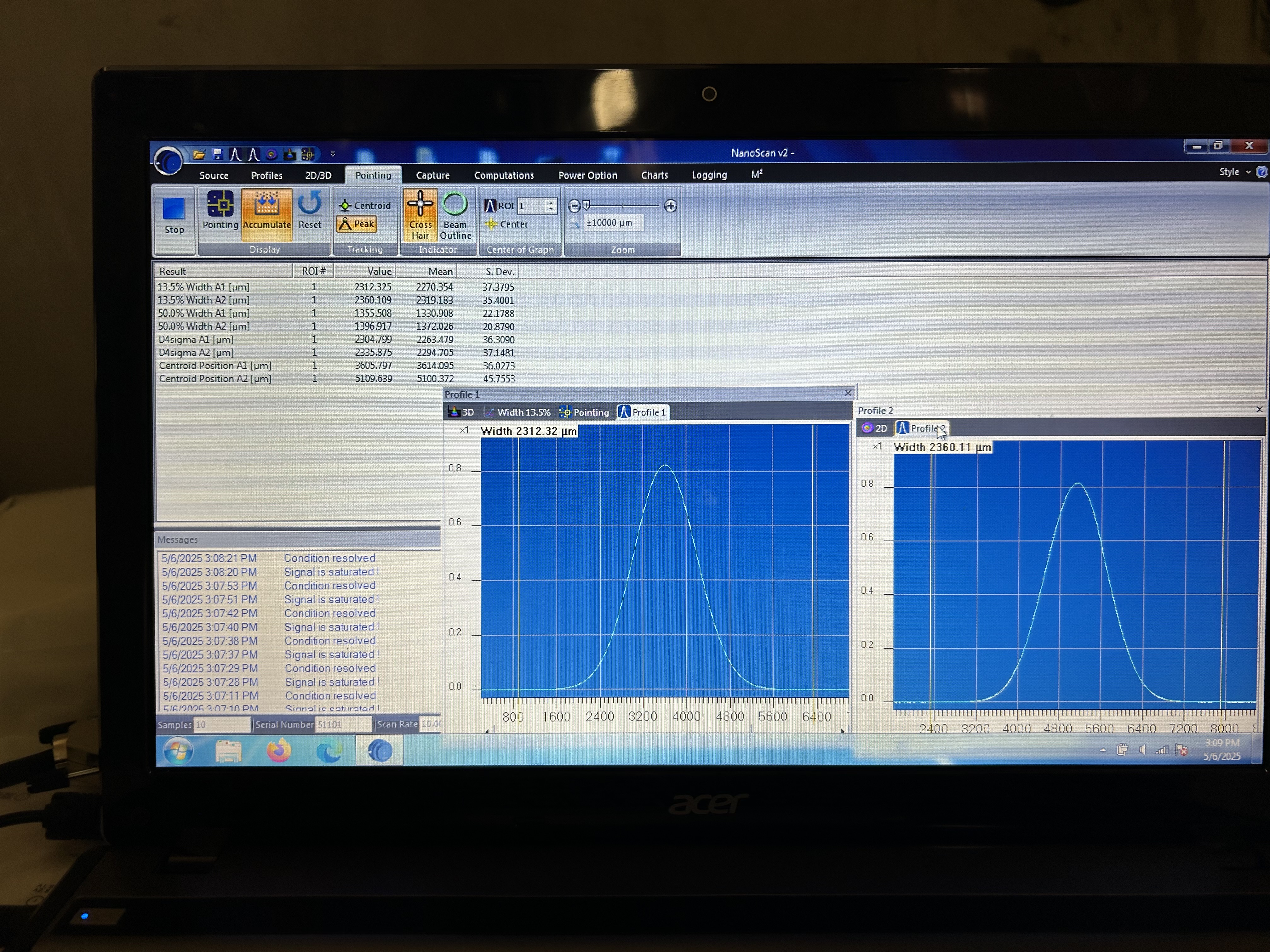
We have taken three beam profile measurements along the REFL path on HAM1: one in the location where REFL WFS B will go, one in the location where REFL WFS A will go, and one measurement further "downstream" where we placed a steering mirror after where WFS B will go and steered back towards the edge of the table. We will post further details later, more measurements to be made along this path tomorrow.
Note that the same glitches we had in the original installation (alog 8934) were still there. Quoting my alog from 2013,
it was still difficult to obtain good data because of some kind of glitches. It's not clear if it was due to NanoScan or the beam, the beam was well damped and was not moving on the viewer card, there was no noticable intensity glitch either. But the symptom was that the statistics window shows nice steady data for anywhere from one second to 30 seconds, then there's some kind of glitch and the scan/fit image looked noticably different (not necessarily ugly), the diameter mean becomes larger and the stddev jumps to a big number (like 10% or more of the mean, VS up to a couple % when it's behaving nice), and the goodness of fit also becomes large. Somehow no glitch made the beam diameter number smaller. I just kept waiting for a good period and cherry-picked.
We measured the beam radius using NanoScan at four points around the WFS sled (roughly WFSA position, roughly WFSB position, far field 1, far field 2). We used D4sigma numbers instead of 1/e**2 numbers. NanoScan outputs diameter not the radius, and the table below shows the raw number.
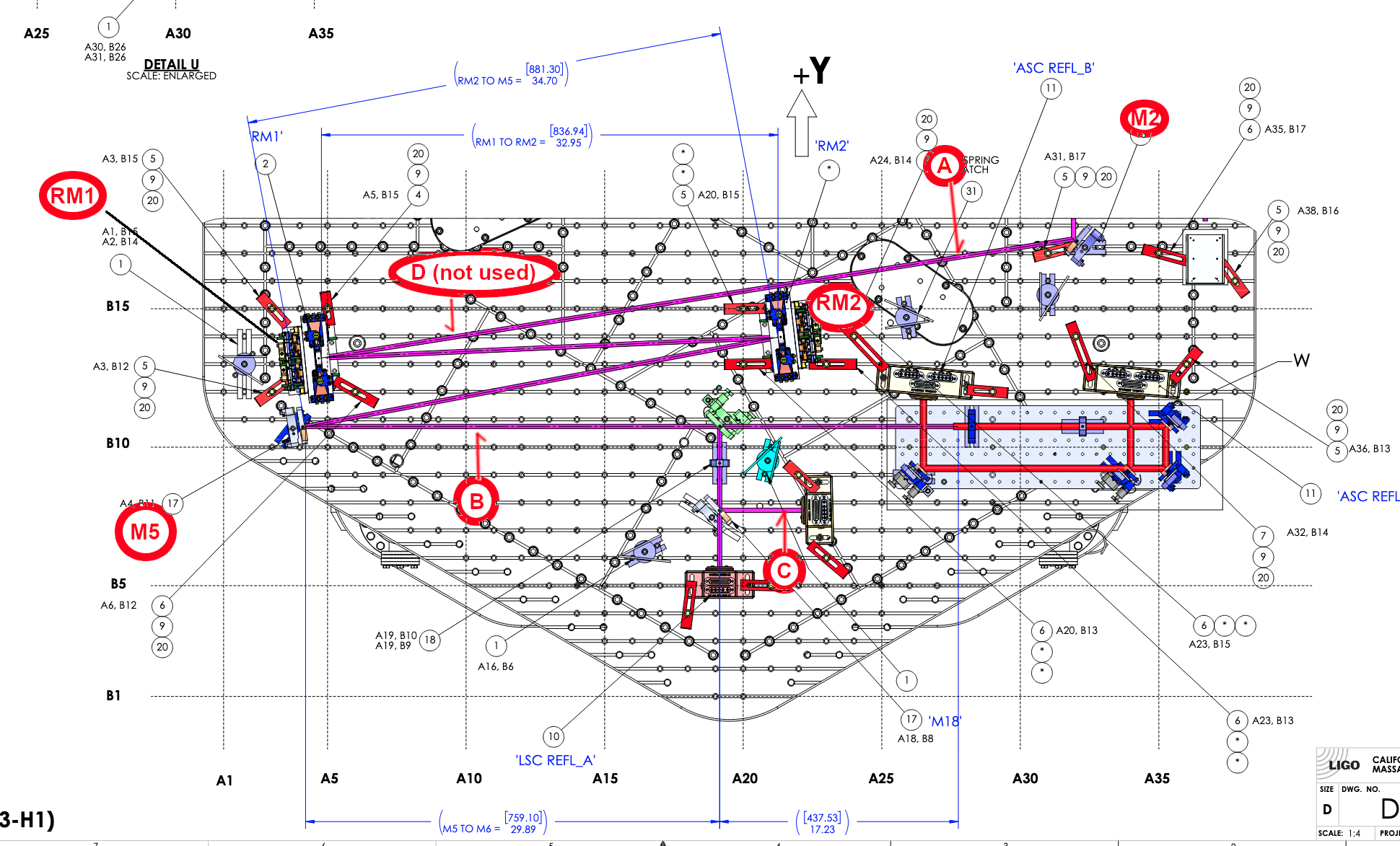
We assumed that the WFS position would be ~0.5" from the +Y edge of the WFS sled for both A and B. Distances were measured using stainless steel rulers and are relative to the 50:50 splitter on the WFS sled that also acts as the steering mirror for WFSa.
| position | distance [mm] | 2*avg(wx) [um] | 2*std(wx) | 2*avg(wy) | 2*std(wy) |
| WFSA | 94 | 670.26 | 2.34 | 778.95 | 2.82 |
| WFSB | 466.5 | 793.73 | 6.38 | 711.29 | 11.95 |
| downstream 2 | 788.5 | 1484.15 | 12.46 | 1387.24 | 58.32 |
| downstream 1 | 1092.5 | 2253.78 | 50.67 | 2119.24 | 68.30 |
In all of the above measurements, "Profile averages" was 10, "Rolling profile Averages" was 3.
We also measured between M5 and 50:50 splitter for ASC-LSC split as well as between M2 and RM1. Numbers will be added to this alog.
We'll also measure the beam size at LSC REFL_B location on Monday before proceeding to POP path.
Here are some comments about the measurement process:
The beam profiler is difficult to use because the profiler head easily swivels once it is place. The swivel seems to be driven by the fact that the cable is very stiff and made stiffer by the addition of the foil so it is cleanroom safe. Several times today, I would pick up or set down the profiler and the head would swivel. I tried tightening the screw holding the post to the base, and I tried tightening the screw that holds the post to the head, but it is not tight enough to prevent swiveling. I found the best method was to line up the profiler in the designed location, and hold the head and cable in place while someone else ran the measurement. That makes this a minimum two person job, but there was enough juggling that having a third person was sometimes helpful.
When we went in around 3 pm to do the final measurement of the day I measured the particle count: 0.3u was 10 and 0.5u was 0. I used the standing particle counter on the +Y side of the HAM1 chamber- briefly unplugged to carry it over to the -Y side for the measurement. I didn't measure when closing up because Keita is heading out to do a few more tasks on HAM1. The handhelp particle counter isn't working, so we have to carry this large one on a stand around to use.
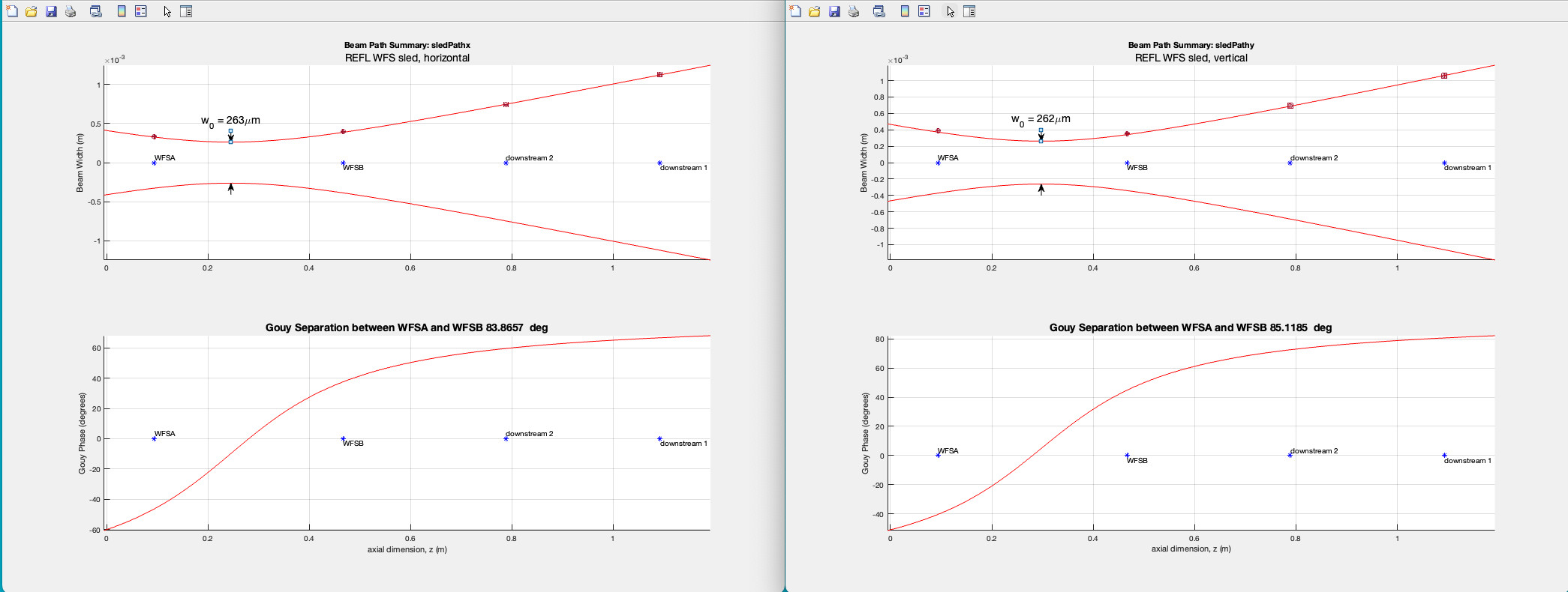
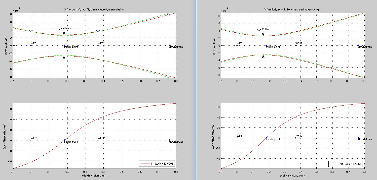
WFS sled is still excellent, 84 to 85 deg Gouy phase separation.
In the attached, four measurement points have error bars both in the position and the beam size but it looks negligible. There's no concern for WFS, it's good to go as is.
However, just for the record, the astigmatism is bigger now (which is inconsequential in that ASC DOF separation is determined by the Gouy phase even if there's an astigmatism). The waist location difference is ~49mm now VS ~14mm or so before (just eyeballing the old plot from alog 8932) for a beam with the Rayleigh range of ~200mm. Not sure if this is the result of the AOI change or beam position change on curved mirrors and lenses, but I won't fix/correct this.
This morning we entered to do one more beam profile measurement. First Jennie and I refoiled the cable of the nanoscan profiler, since it was very stiff from multiple layers of foil. Then, before opening the cover to the table, I measured the dust counts by carrying the stand particle counter over to our working side like I did on Friday. The read was 0 and 0 for 0.3um and 0.5 um particles. I know it was working however, because as I carried the counter over outside the cleanroom it counted 19 each of 0.3 and 0.5 um particles.
Then, Jennie and I took one more beam profile measurement, this time on the LSC REFL path, after the final beamsplitter (M18). LSC REFL A (on transmission of M18) is placed on the table as in the drawing, but the LSC REFL B sensor (reflection of M18) was further away relative to the splitter. My quick rough measurement showed that LSC REFL B was about 160 mm away from M18.
I measured the distance of LSC REFL A to the front surface of M18 to be 128 mm. Then, I set LSC REFL B off to the side, and placed the profiler about 128 mm away from M18 on reflection of the splitter. We measured the beam profile, and then I re-placed LSC REFL B, this time at a distance of 128 mm to M18.
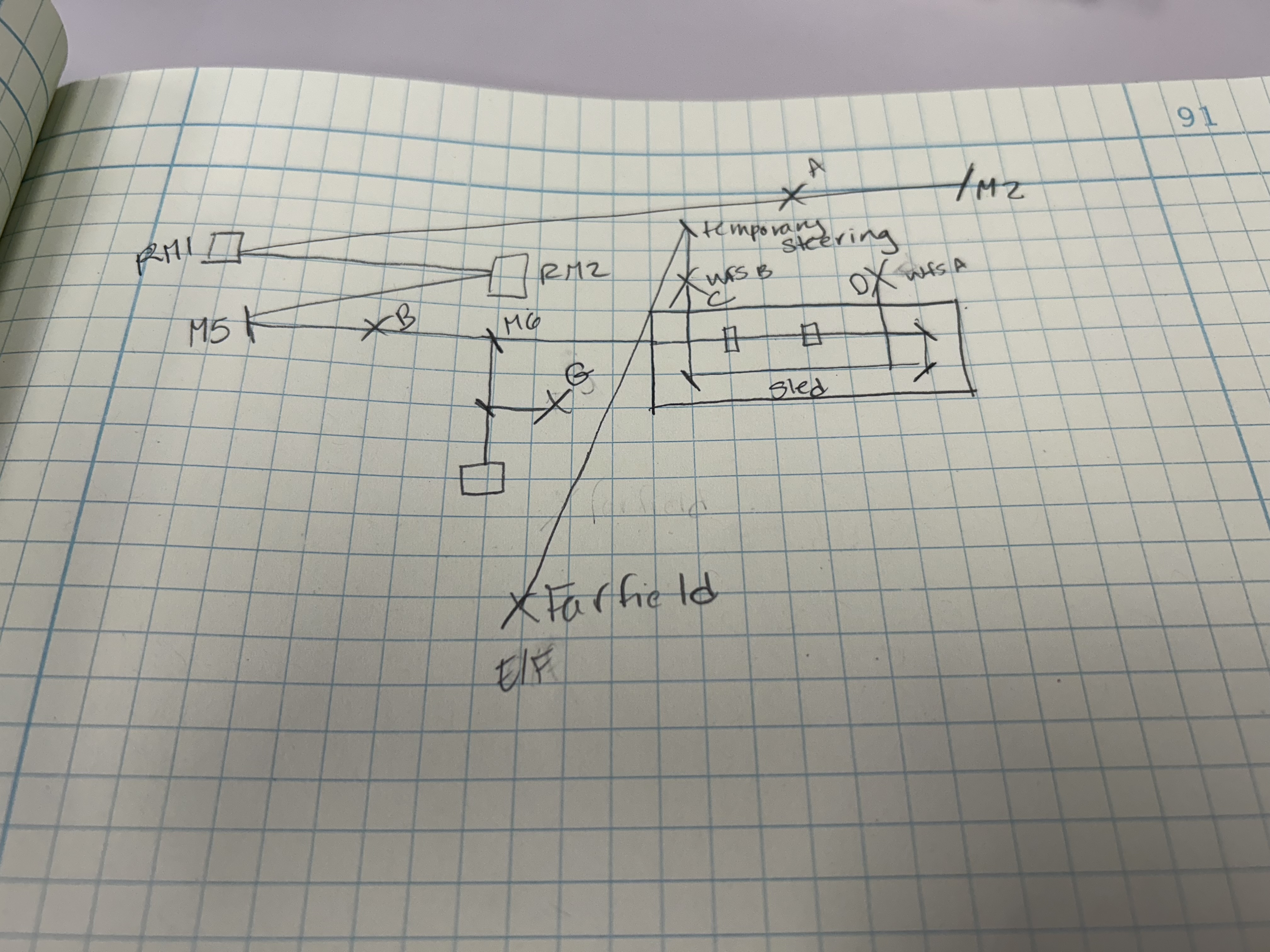
I have attached a very rough drawing of the REFL path and the locations where we made beam profile measurements. Each X on this drawing marks a beam profile measurement location. I also marked the Xs with letters A-G.
The measurements Keita reports above correspond the measurements C, D, E and F on this drawing. The difference between E and F, which is not depicted in my drawing, is a different placement of the temporary steering mirror relative to the sled.
We still need to report details on the measurements for locations A, B, and G.
Beam size upstream of the WFS sled
Unfortunately this is preliminary.
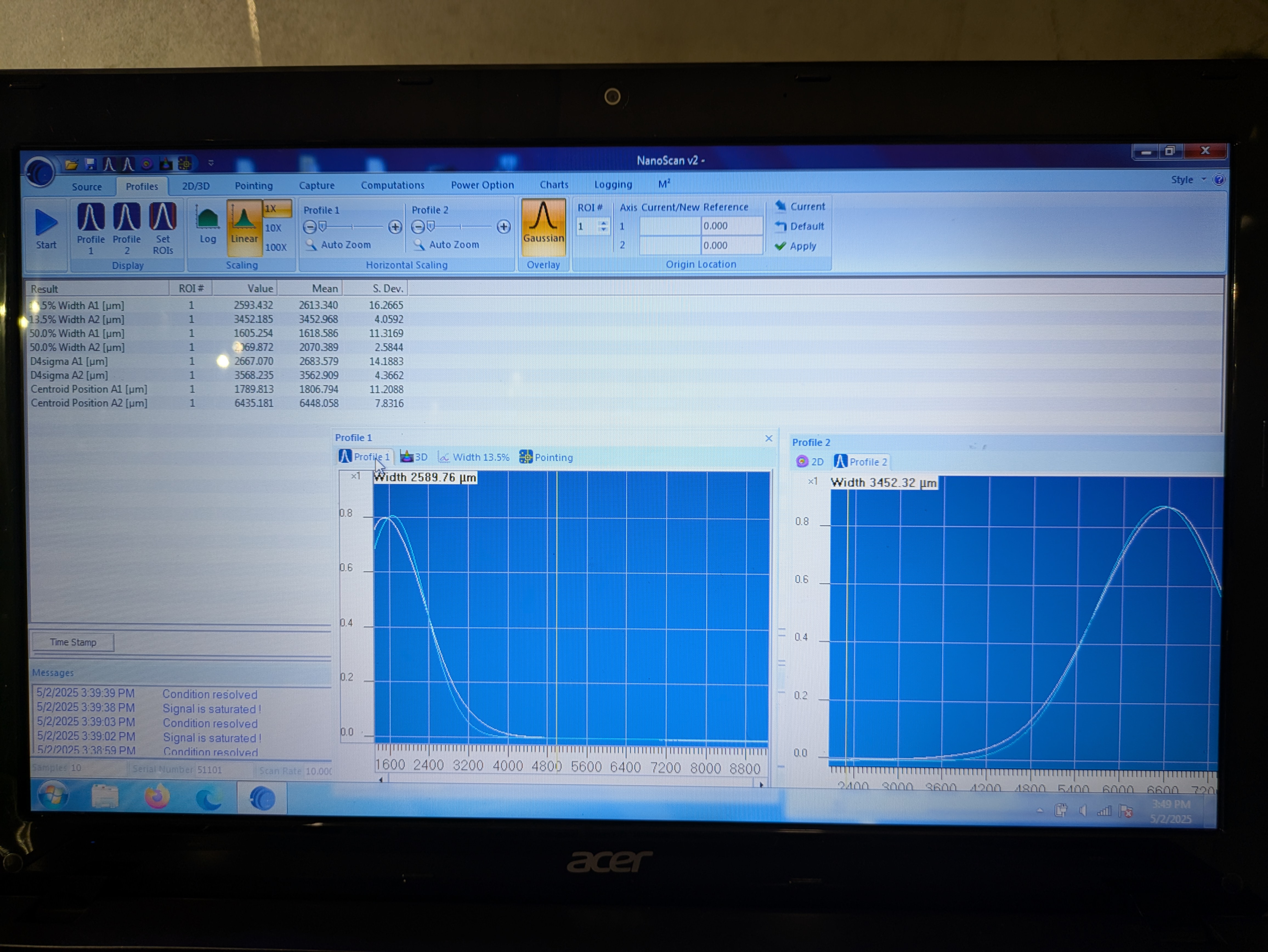
We measured the beam size at 4 different location upstream of the WFS sled marked as A, B, C and D. D data cannot be used as there's no data/picture of D locaiton but that's fine as far as position A data is good. Unfortunately, though, the position A horizontal width looks narrower than it really is (2nd attachment). The beam might be clipping in the nanoscan aperture or there might be a ghost beam or bright background light in the Region Of Interest (ROI), or ROI is defined poorly, effectively clipping the beam. Must remeasure.
LSC REFL_B (and therefore REFL_A) beam radius is ~0.1mm, which is tinier than my preference, the diode is 3mm (in diameter) so the beam could be larger. The diodes are placed close to the focus of the lens upstream (number 18 in a circle in the first attachment) so the beam won't move when the beam position moves on that lens. Moving away from that position will be fine as far as the deviation is much smaller than the focal length (~200mm). Rayleigh range is like 3cm or maybe smaller (0.1mm waist -> RR=10*pi mm), it should be easy to double the beam size by moving the sensors away from the lens by a couple inches. We'll do this after POP alignment.
| Location | Distance from the closest component | wx [um] | std(wx) [um] | wy [um] | std(wy) [um] |
| A |
225mm downstream of M2, hard to measure the position accurately. Nanoscan wx*2 number looks narrower than it really is. Must remeasure. |
2683.6/2
|
14.2/2
|
3562.9/2 | 4.4/2 |
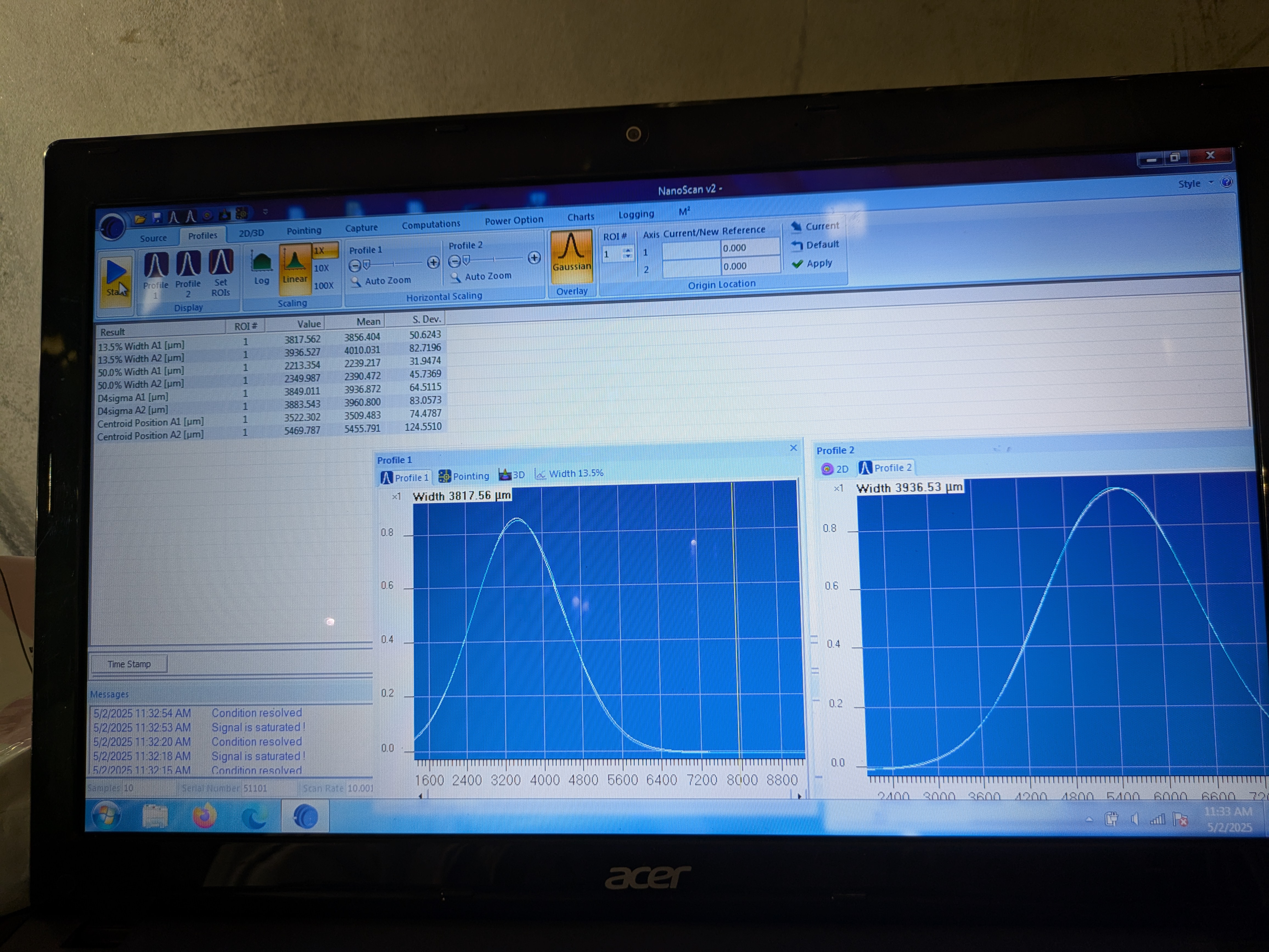
| B | 303mm downstream of M5. | 3936.9/2 | 64.5/2 | 3960.8/2 | 83.1/2 |
| C |
128mm downstream of the last 50:50 for LSC REFL_A/B. LSC-REFL_B location (tentative). |
211.6/2 | 12.7/2 | 247.3/2 | 4.5/2 |
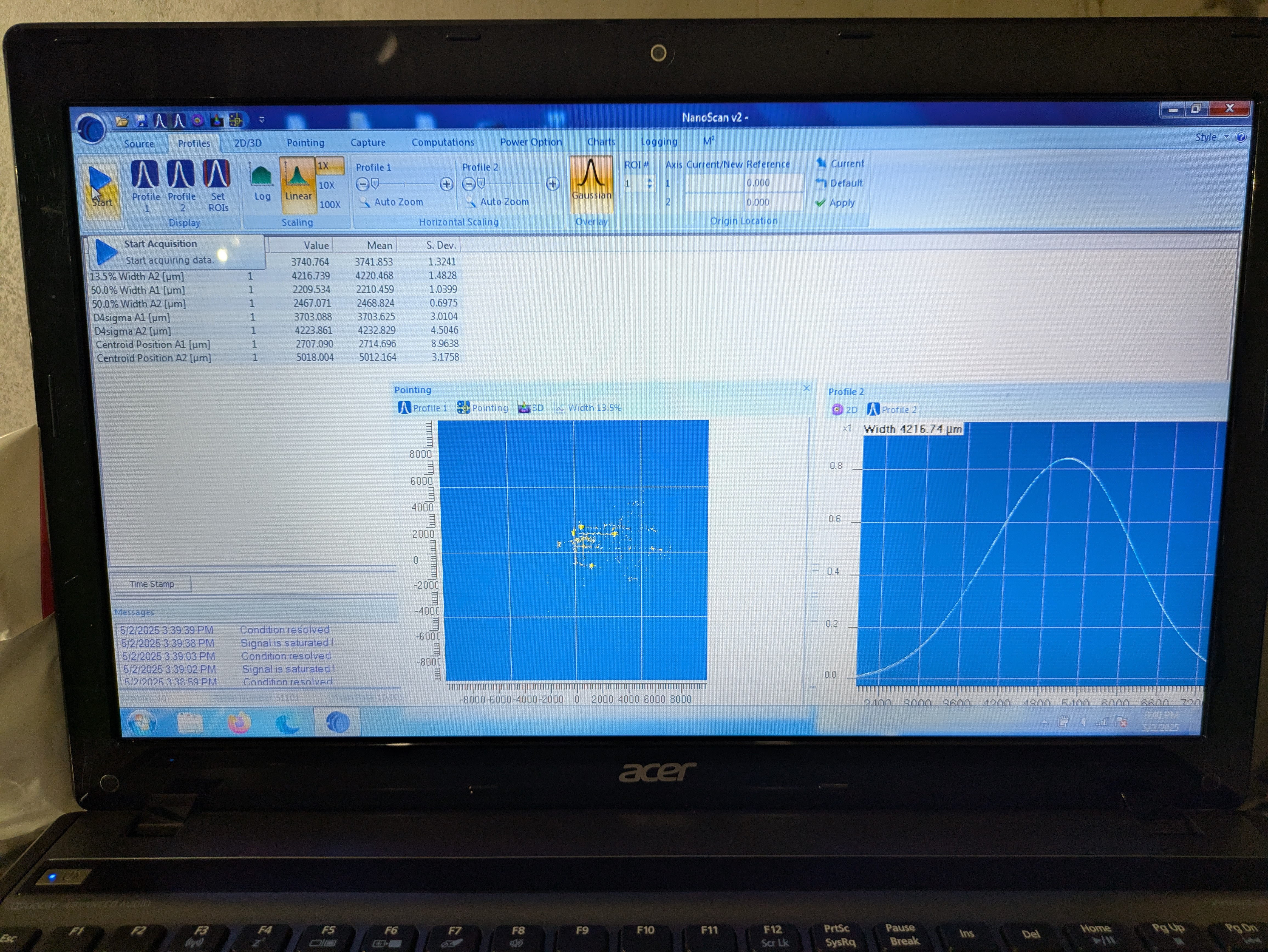
| D | Exact position unknown, between RM1 and M2, less than 1400 downstream of M2. Beam size numbers look good. | 3703.6/2 | 3.0/2 | 4332.8/2 | 4.5/2 |
After everything is done we'll make a good measurement of distances between everything by either using a long/short ruler (preferred) or counting bolt holes or both.
Yesterday Betsy and I measured the distances between these optics:
Camilla and I went back out today to redo the measurements at the locations labeled "A" and "D" in Keita's diagram. This table reports the D4sigma values, like Keita's tables above.
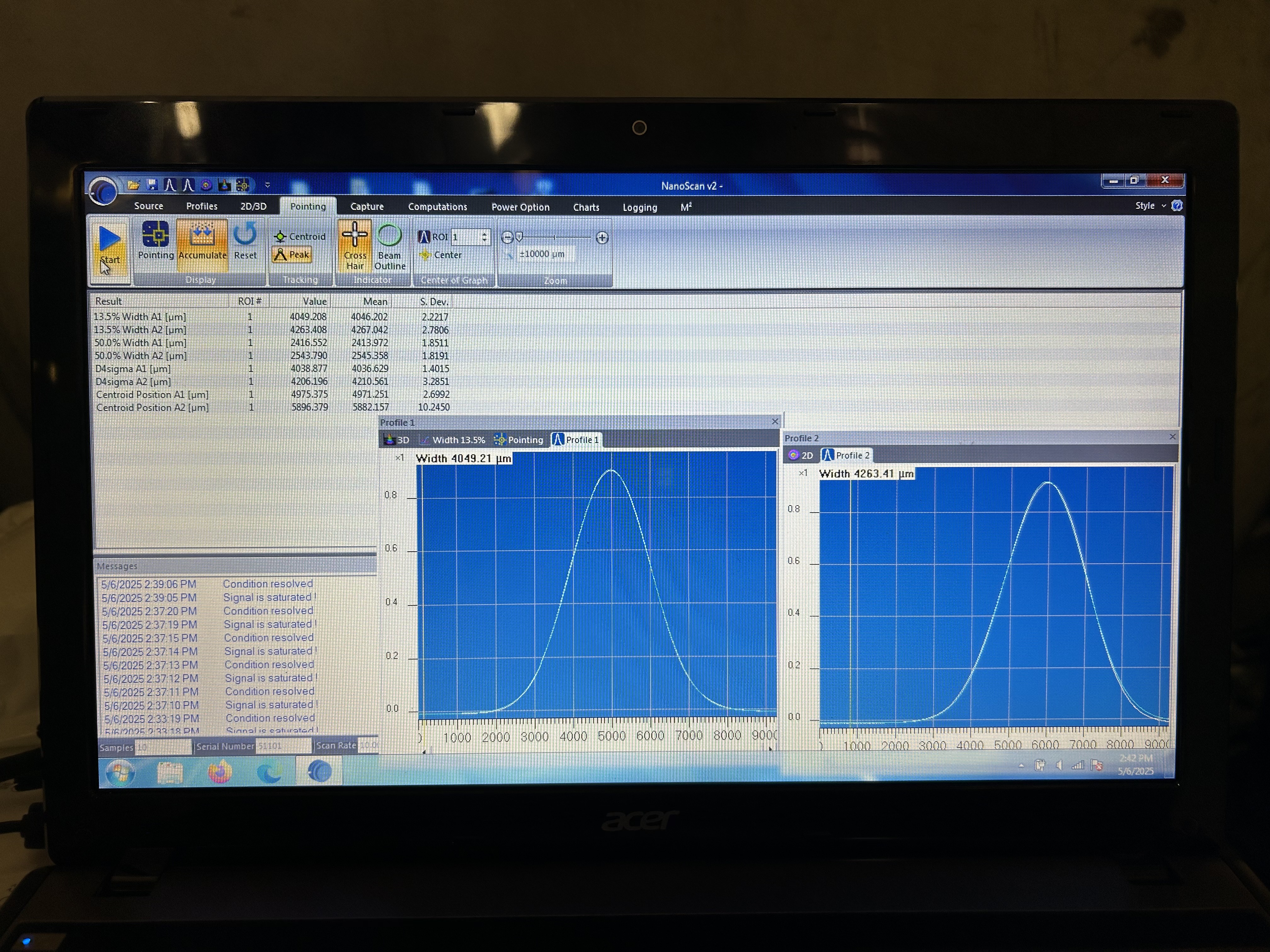
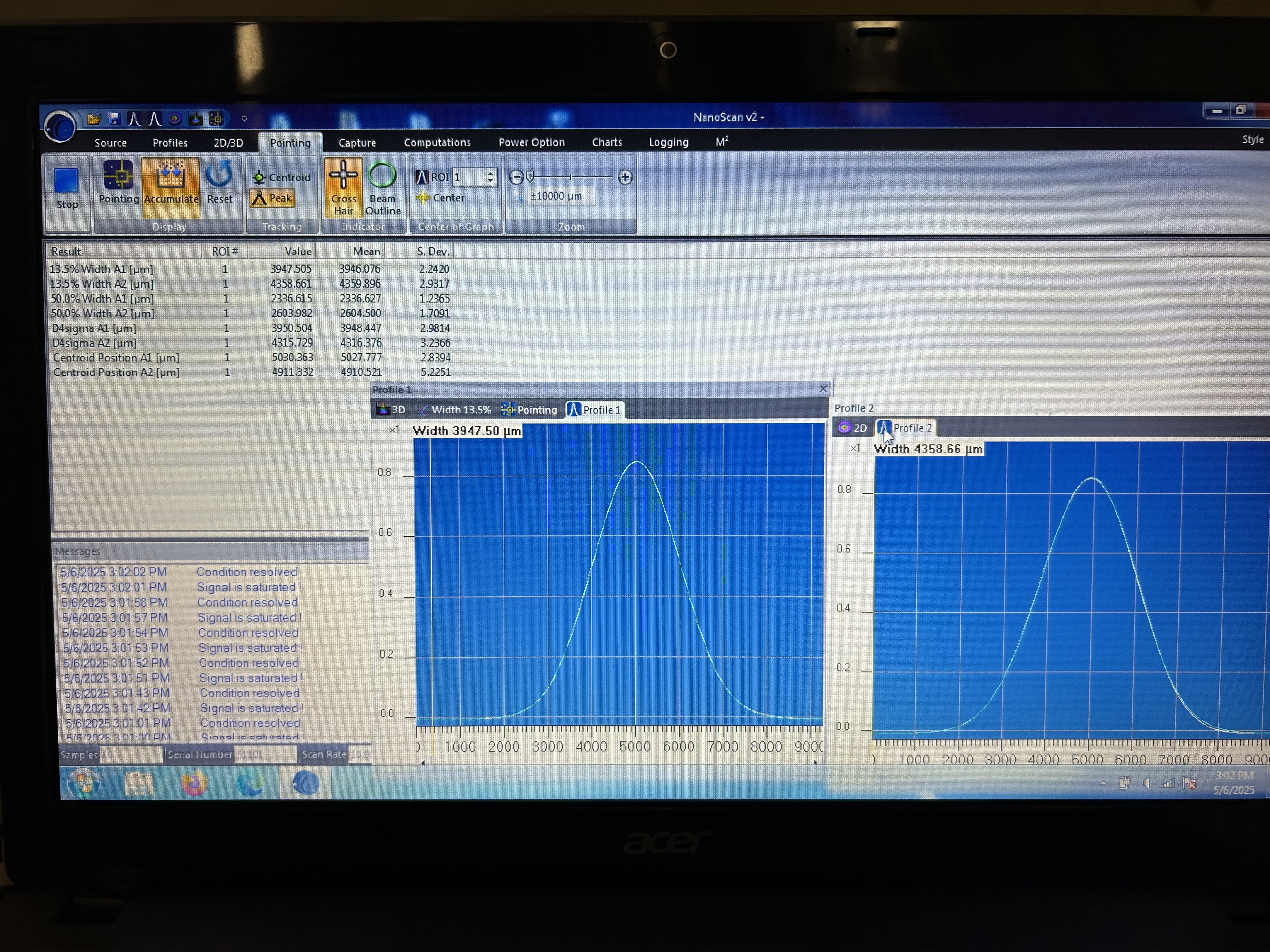
We forgot that we had left ITMX aligned, so the original measurements in this alog are no good. Keita and I remeasured these again today (May 6) and I am updating the table below with the new data. We also got two more measurements in new locations that are not indicated in Keita's diagram.
| Location | Distance from closest component | wx [um] | std wx [um] | wy [um] | std wy [um] |
| A | 238 mm (+- 3 mm) downstream of M2 (nanoscan image) | 4038.9/2 | 1.4/2 | 4206.2/2 | 3.3/2 |
| D | 314 mm (+- 3 mm) upstream of RM1 (measured from nanoscan front to metal ring around the RM, the mirror surface may be set back from the ring by another 1mm or so, hard to tell) (nanoscan image) | 3950.6/2 | 2.8/2 | 4315.0/2 | 2.6/2 |
| New location, after RM2 | 374 mm upstream of M5 (nanoscan image) | 2304.8/2 | 36.3/2 | 2335.9/2 | 37.1/2 |
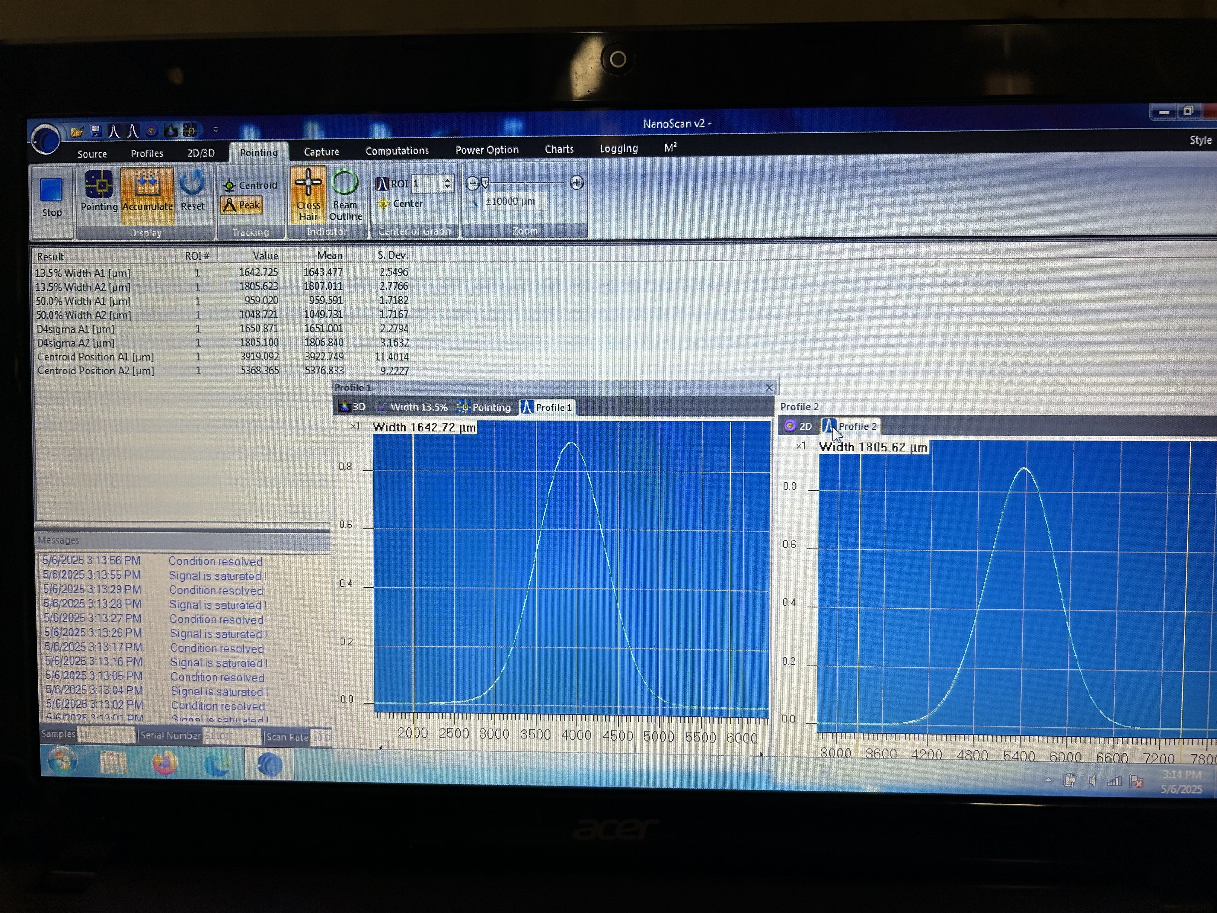
| New location, between RM1 and RM2 | 345 mm upstream of RM2 (measured from nanoscan front to metal ring around RM) (nanoscan image) | 1650.9/2 | 2.3/2 | 1805.1/2 | 3.2/2 |
Leaving this older comment: It is difficult to measure these distances well with the ruler, so I would guesstimate error bars of a few mm on each distance measurement reported here.
Some new notes: when we reduce teh purge air flow, the measurements become much more stable and there is no need to "cherry pick" data as Keita discussed in earlier comments. Also, I think we have finally managed to tighten the screws on the nanoscan posts enough that it doesn't slide around anymore.
Keita, Elenna, Jennie, Betsy, Camilla, Jordan, Sheila
Summary: All diodes now cabled correctly, the periscope is installed and septum cover off ready for starting POP beam alignment, beam profiling is in progress.
beam height measurements.