Activity Log: All Times in UTC (PT)
00:00 (16:00) Take over from TJ
01:10 (17:10) Reset L4C WD saturations on HAM2, HAM3, HAM4, HAM5, & ITMX
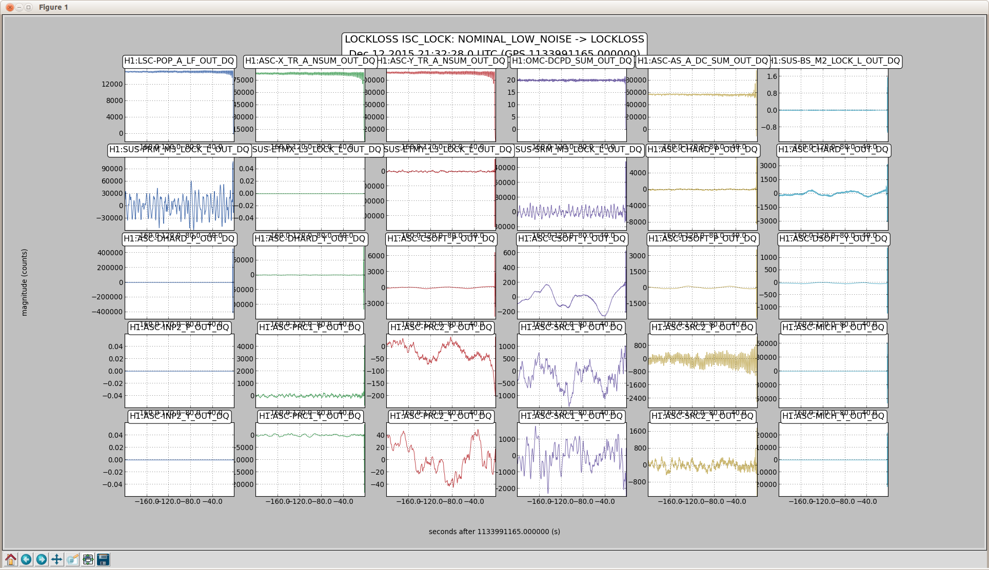
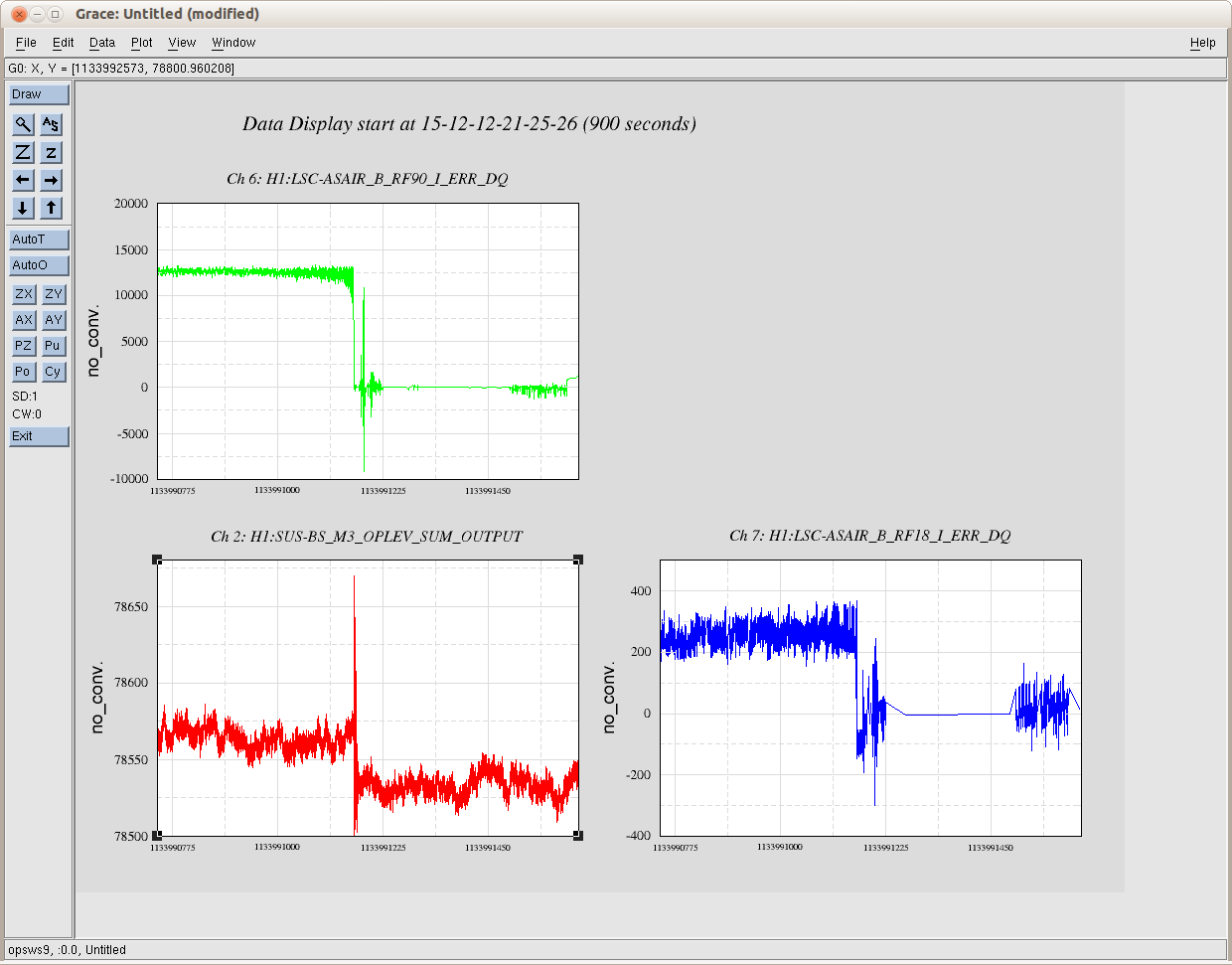
02:57 (18:57) Lockloss – High winds (35 to over 40), elevated seismic & microseism
03:15 (19:15) Temp alarm on CD Zone 4 heating duct – Temp @ 104.5f, will monitor
07:15 (23:15) Reset timing error on H1SUSETMY
08:00 (00:00) Travis on site
08:50 (00:50) Turn over to Travis, who is working with Peter
End of Shift Summary:
Title: 12/12/2015, Evening Shift 00:00 – 08:00 (16:00 – 00:00) All times in UTC (PT)
Support: Peter King
Incoming Operator: Travis
Shift Detail Summary: Lockloss at 02:57 (18:57) – Probable cause high winds (40 plus at along X-Arm) and elevated seismic (0.1um/s Plus) & microseism (centered at 0.8um/s, but peaks well over 1.0). Weather conditions are expected to be stormy until 06:00 (22:00). Will try relocking.
IFO is not relocking. Has not gone past DRMI_1F. Started to run initial alignment, however CS and Y-Arm now recording wind speeds in excess of 30mph with several gusts over 40mph. Seismic and microseism are also elevated. Put the instrument into Down until the wind lays down a bit.
Wind is down to the lower 20 to mid teens, so going to try relocking after initial alignment. Part way through initial alignment wind piped back up to over 30 at End-Y and the high 20s elsewhere. During SRC_ALIGN ASC could not converge before being knocked back to down then restarting the SRC_ALIGN. Appears to be a little soon to try alignment and locking. Perhaps the Owl shift will have better conditions and success.
Found IMC_MC2_Trans oscillating after aborted SMC alignment. ISS diffracted power was also oscillating. Called Peter King. Tried to get things stabilized by varying first loop, refsignal levels, etc. but without much luck. Turning over to Travis so I can get some sleep before tomorrow’s Owl shift.