TITLE: Dec 9 DAY Shift 16:00-00:00UTC (08:00-16:00 PDT), all times posted in UTC
STATE Of H1: Observing
SUPPORT: Sheila, Hugh, TJ, Jenne, Robert and Jordan
LOCK DURATION: 36min
INCOMING OPERATOR: Nutsinee
SHIFT SUMMARY:
-
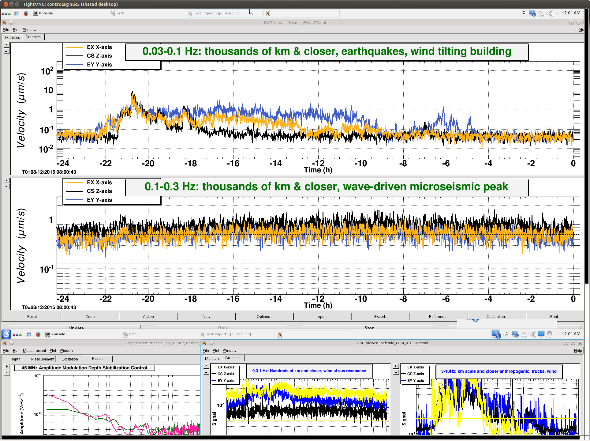
A combination of high microseism and high winds, for most of the day, made it less than possible for locking.
-
Twice today the call for doing maintenance was made.
-
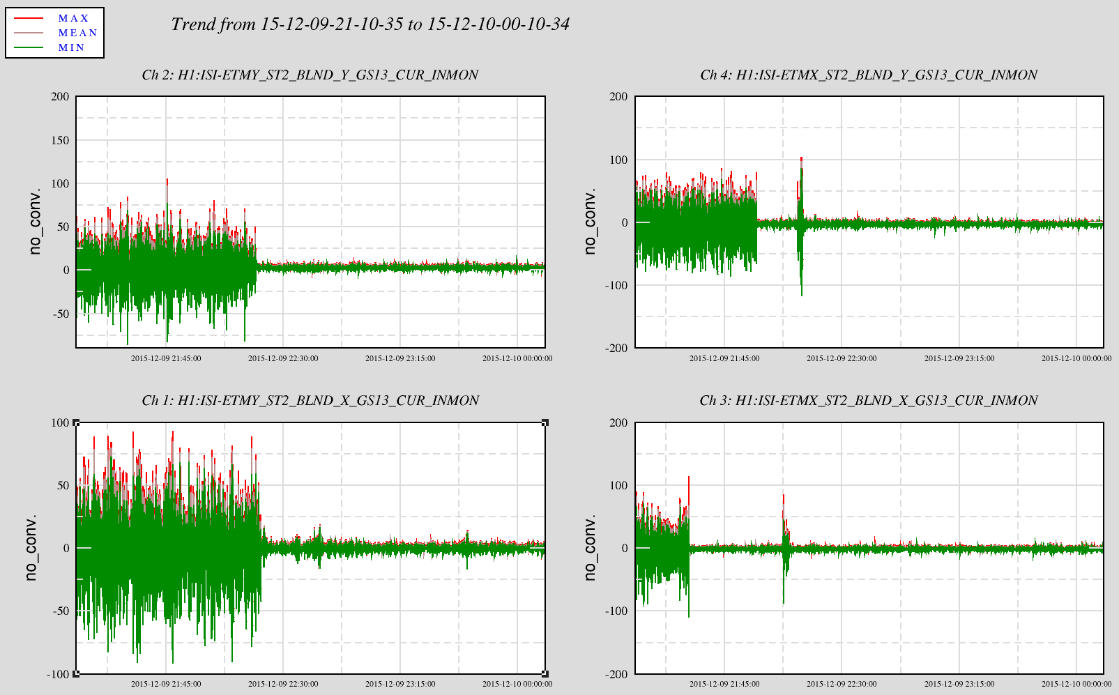
Hugh and Sheila were able to determine the best blends to use at the End Stations for locking today.
-
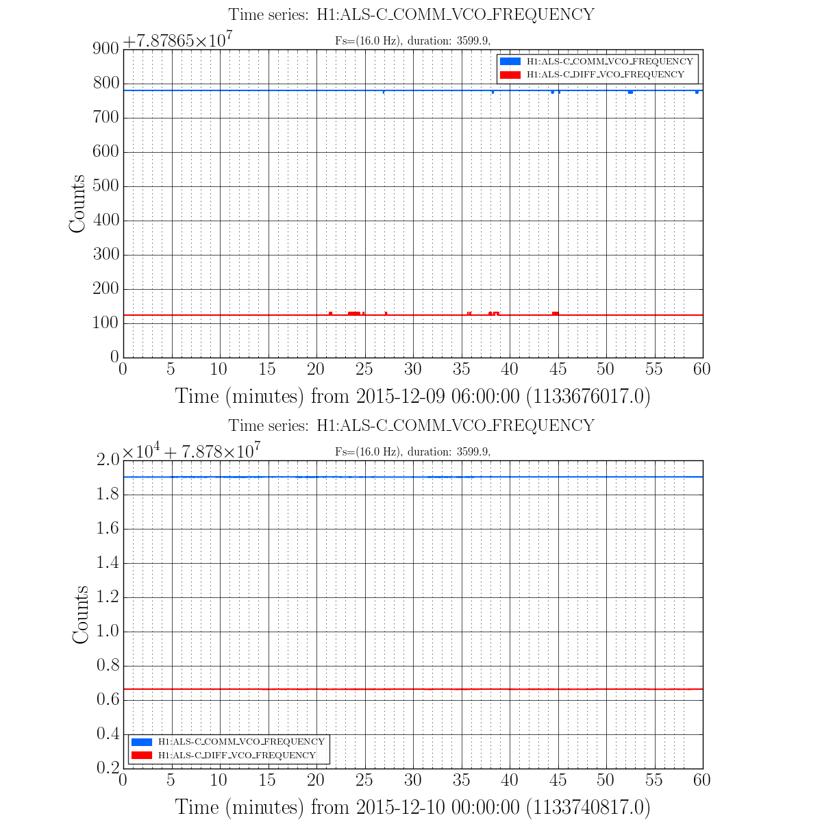
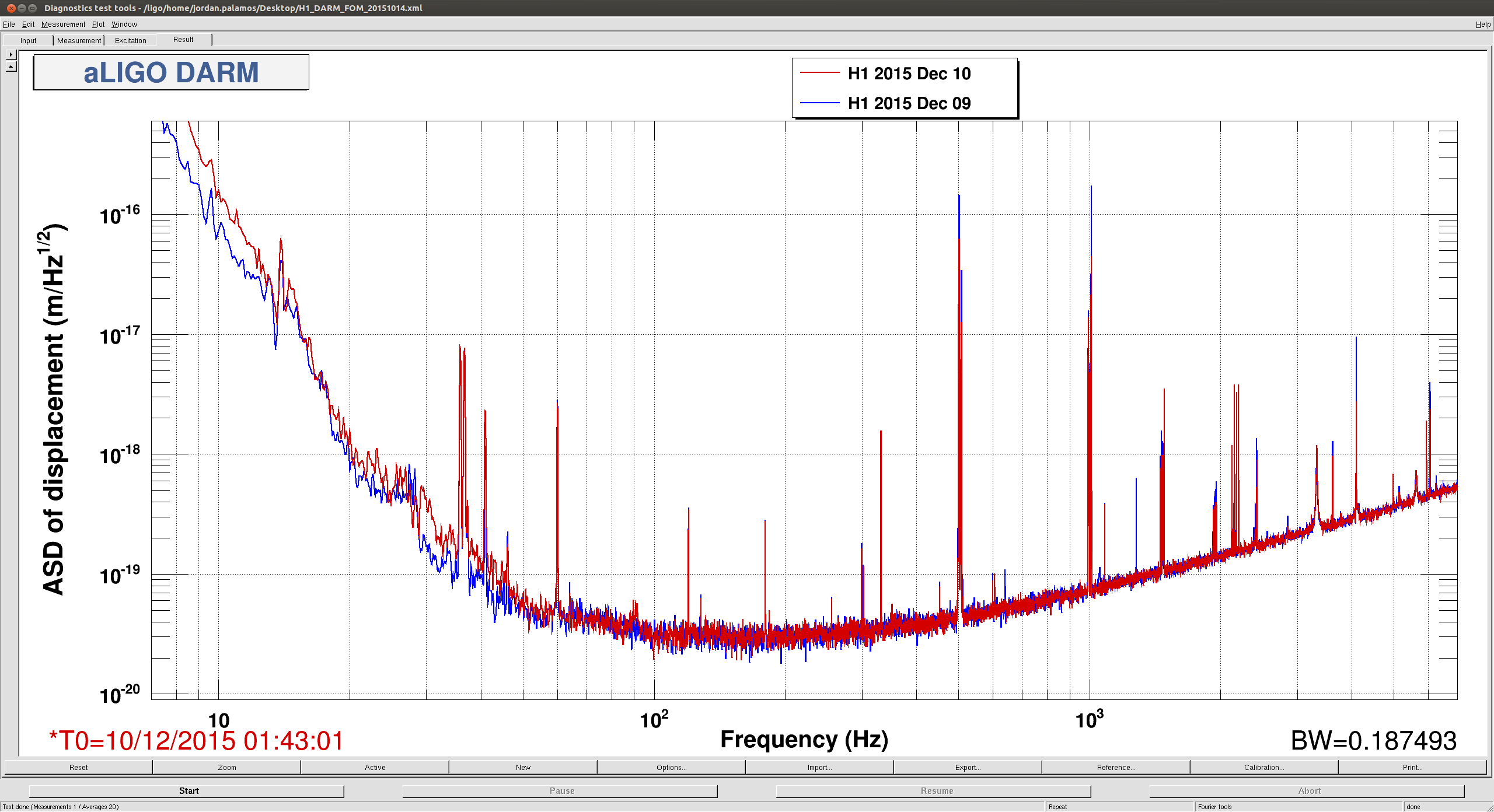
Sheila, Jordan and Robert tweaked the COMM VCO to get rid of some unwanted lines in DARM
-
DRMI Lock was finally achieved at 23:02UTC
-
Intention Bit set to Undisturbed at 23:50UTC
-
There is a timing error showing in the ETMX CDS overview that got forgotten. It can be reset in the case of lockloss.
ACTIVITY LOG:
16:15 Fil out to LVEA to do some more cable pulling
16:25 Jeff Bartlett and Mitch out to LVEA to do some more work on dust monitor plumbing
16:30 Peter into LDR
16:40 Peter out of LDR
17:01 Jeff and Mitch out of LVEA
17:03 Jeff and Mitch to EX
17:21 Richard called to let me and Mike know that he has started his work in the CER.
17:40 Gerardo out to Y-2-8 to refuel the generator
17:54 Richard, et al, are finished in the CER and are heading down to EY.
18:19 Bubba heading to MX to work on a fan.
18:39 Gerardo back from Y-2-8
21:22 Kyle to Y-2-8 to take some temp readings
21:55 Kyle back to corner station
23:21 H1 is locked at Nominal Low Noise!
23:50 Intention Bit set to UNDISTURBED