This is a classic tale of IM1-3 woes - IM1-3 are very likely to move when the HAM2 ISI trips, so need to be checked every time.
The IMs come from IOO, so they are unlike any other optics we have, and so behave in a very different way, and are suscetable to changing alignment when they experience shaking, like they do when the ISI trips.
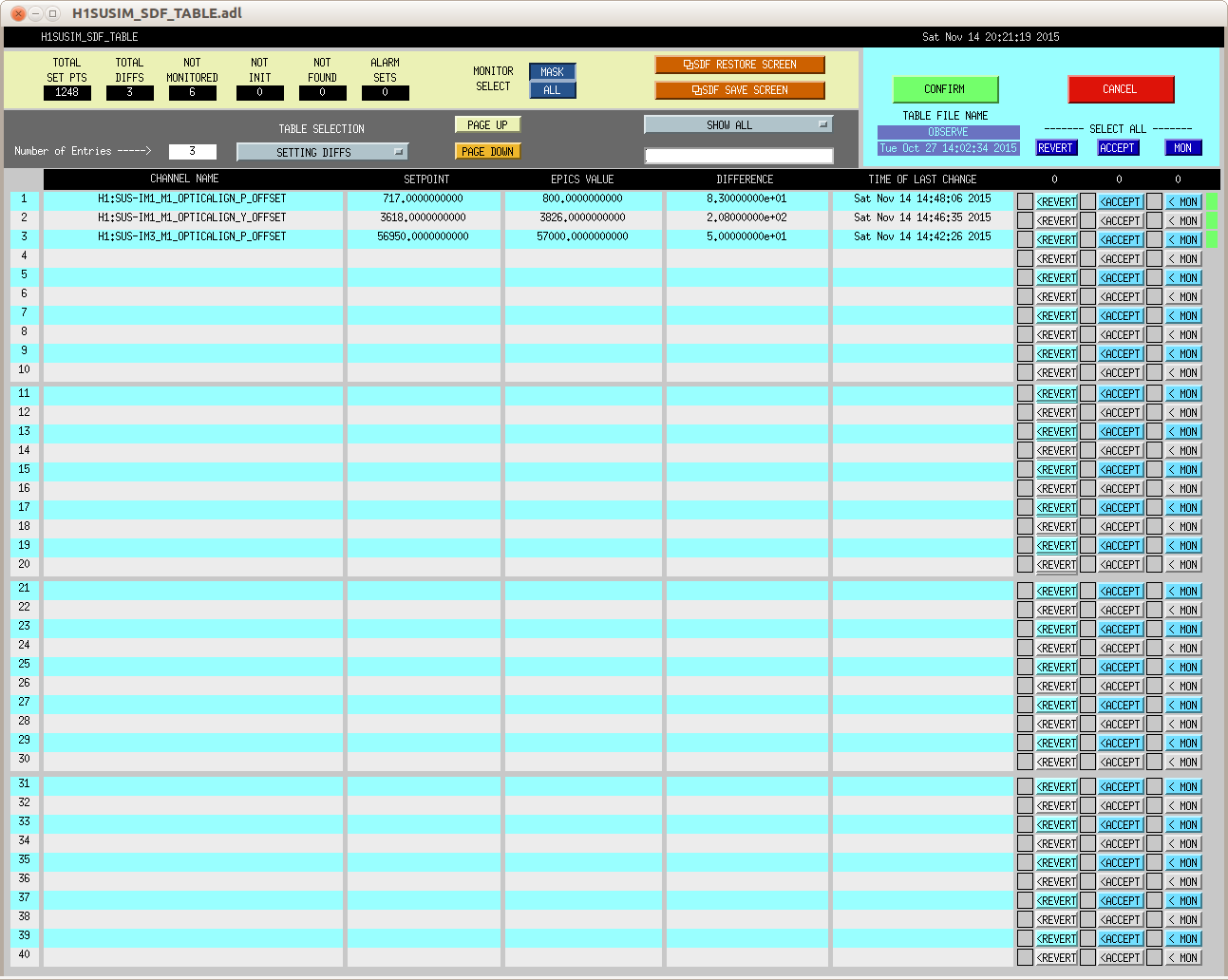
The IM OSEM values are consistant, and when the optic alignment shifts, it is consistantly recovered by driving the optic back to previous OSEM vlaues, regardless of slider values. The OSEM values, when restored, consistantly restore the pointing onto IM4 Trans QPD.
IM4 Trans QPD reads different values for in-lock vs out-of-lock, so it's necessary to trend a signal like OMC DC A PD to correctly compare times.
IM4 does sometimes shift it's alignment after shaking, but because it's moved around by the IFO, choosing a starting value can be difficult. In the case of IM4, restoring it's alignment to a recent out-of-lock value should be sufficient to lock, but ultimately IM4 needs to be pointing so that we can lock the X arm in red.
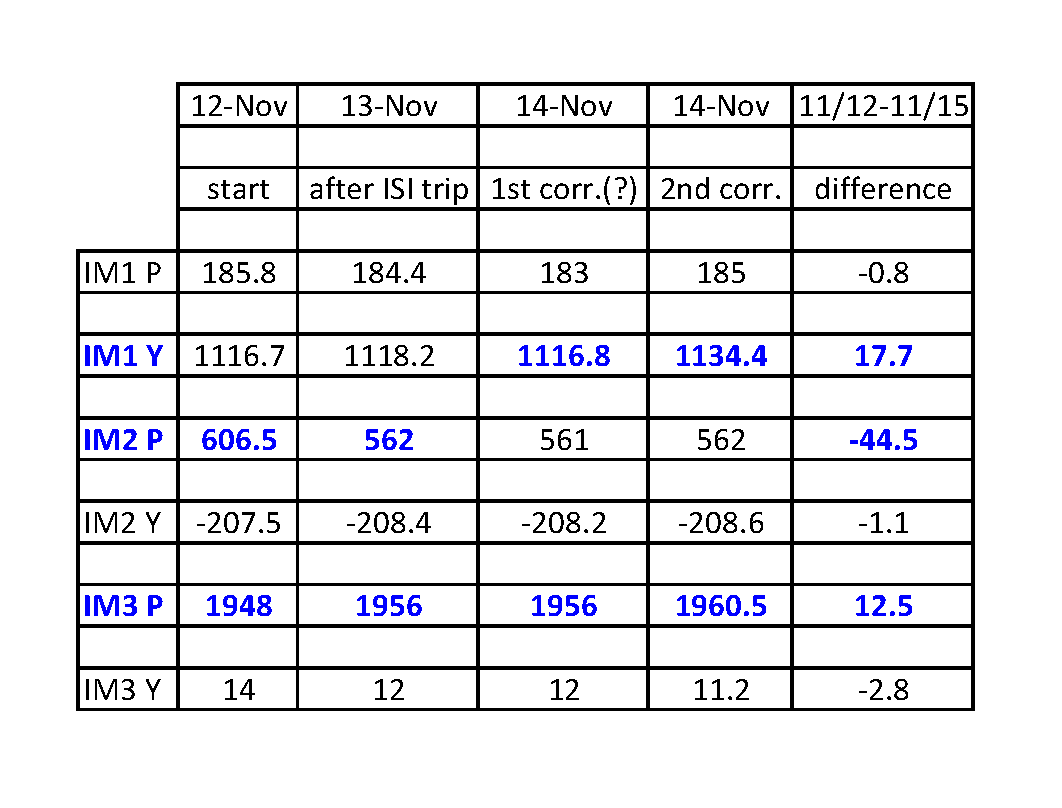
I've tracked the alignment changes for the IM1-3 since 9 Nov 2015, and they are listed below.
- 11/12, starting values, all optics change by only around 2urad for the previous 3 days (11/9-11/12)
- 11/13, the ISI tripped, and IM2 Pitch changed by 40urad, and IM3 Pitch changed by 8urad
- 11/14, around 00:30UTC, there's a clear step in signals, but alignment is unchanged, possible 1st attempt at correcting alignment (?)
- 11/14, around 23:45UTC, an alignment correction, however optics do not retun to starting values
These alignment changes are big enough to effect locking, and it's possible that the IFO realignment that was necessary last night was in part a response to IM pointing changes.
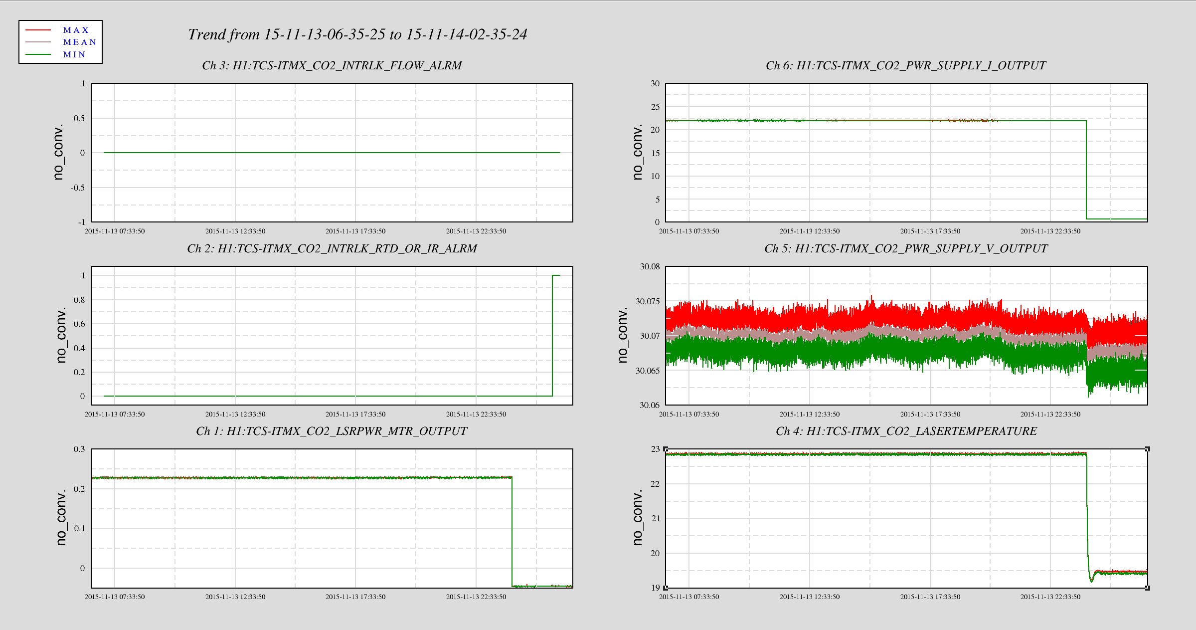
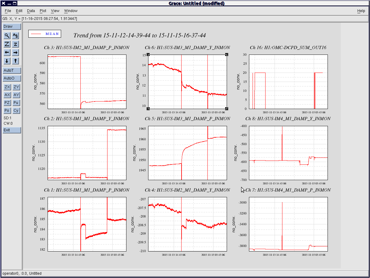
I've attached plot showing the IM alignment channels.
Armed with those channels, and the knowledge that the IM OSEM values are trustworthy, and the knowledge that under normal running conditions IM1-3 only drift 1-2urad in a day, checking and restoing IM alignemt after a shaking event (ISI trip, earthquake) should be a fairly quick process.
Thanks for the write-up here, Cheryl!
General Statement:
Honestly, when it comes to gross misalignments (those which CANNOT be fixed with an Initial Alignment; usually caused by something catastrophic [i.e. power outage, huge earthquake, etc]), I don’t have an idea of where to start.
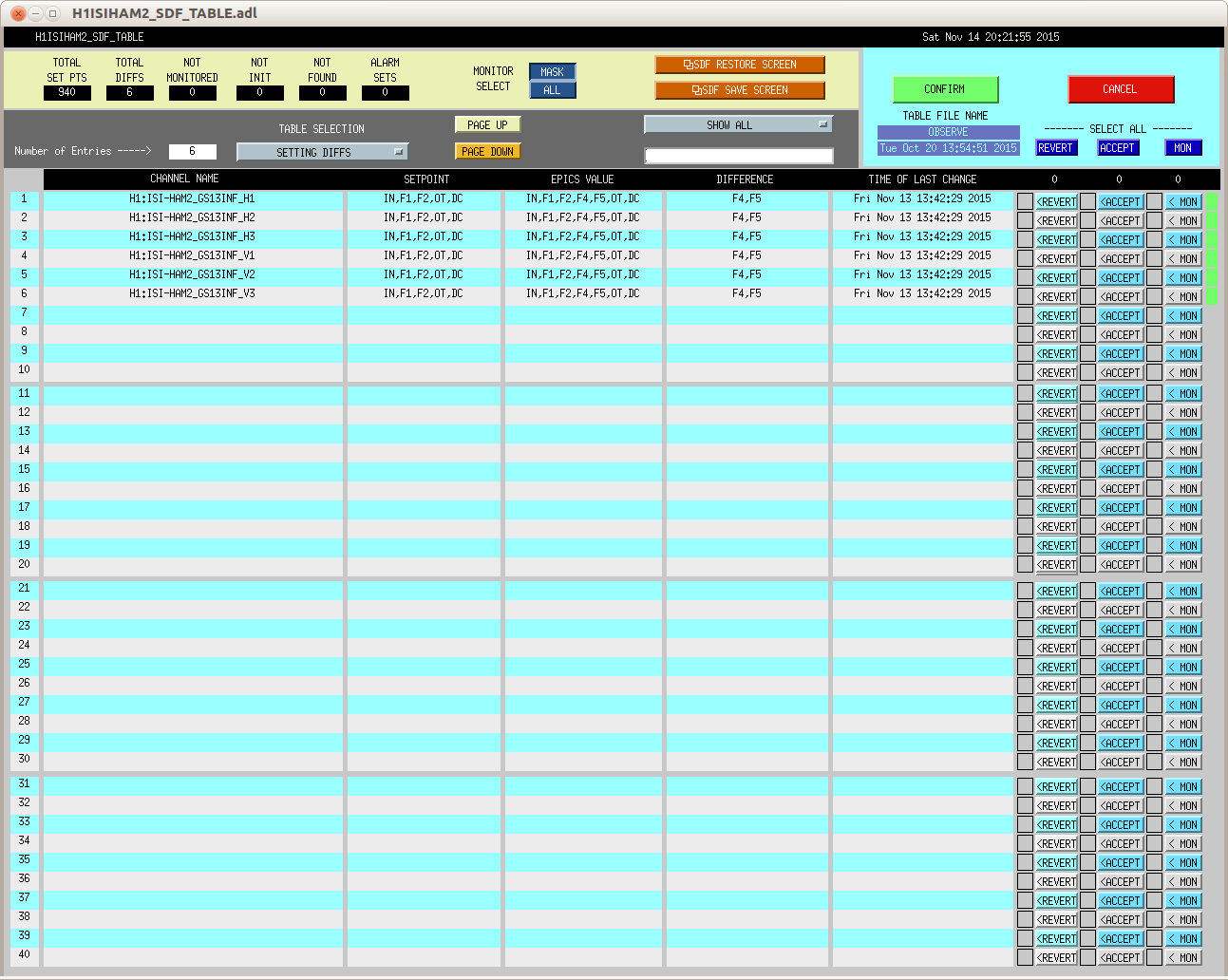
For example, what specific channels does one check for misalignments (i.e. specific channel name, is it same for all optics? What about for ISIs/HEPI, do we need to check them for misalignment?). This is a more specific question for IO, SUS, SEI, & TMS.
Specific Statement/Question:
It sounds like you are finding that the Input Mirrors (IMs) are more susceptible to “shakes” from SEI; whereas since SUS’s are so much different and bigger, they aren’t as susceptible. This is a big thing, and we should pay attention to changes to the IMs.
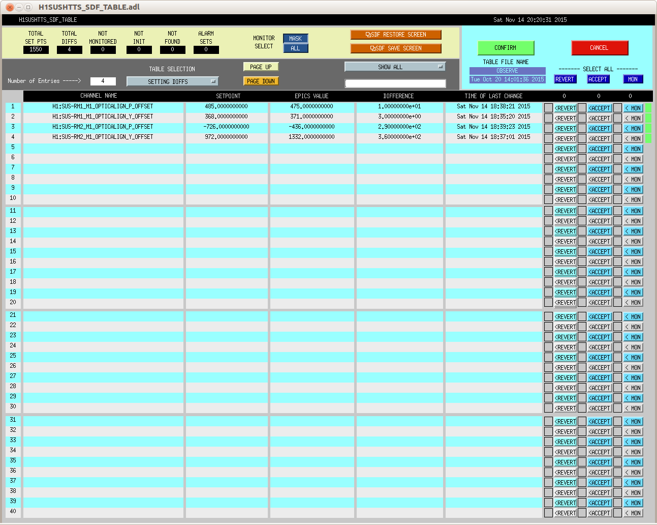
Side question: Are the IMs similar to the Tip Tilts?
For input pointing misalignments, what is the cookbook/procedure for checking & fixing (if needed) alignment? Sounds like we:
- Check IM4 Trans QPD (what’s channel name?)
- Check IM OSEMs (need specific channel you prefer). What are all the IM optics we need to look at specifically?
- Restore OSEMs, if needed (is that an obvious slider?)
- Confirm IM4 Trans QPD is back to a good state.
All of this can be done in the control room, yes? Do we ever have to go out on an IO table?
I’d like something similar for SUS, TMS, & SEI. What signals (specific channels) is best to look at to check for alignment of each suspension or platform?
Anyway, thank you for the write-up and helping to clarify this!