patrick.thomas@LIGO.ORG - posted 00:08, Sunday 29 November 2015 - last comment - 01:30, Sunday 29 November 2015(23791)
Current State
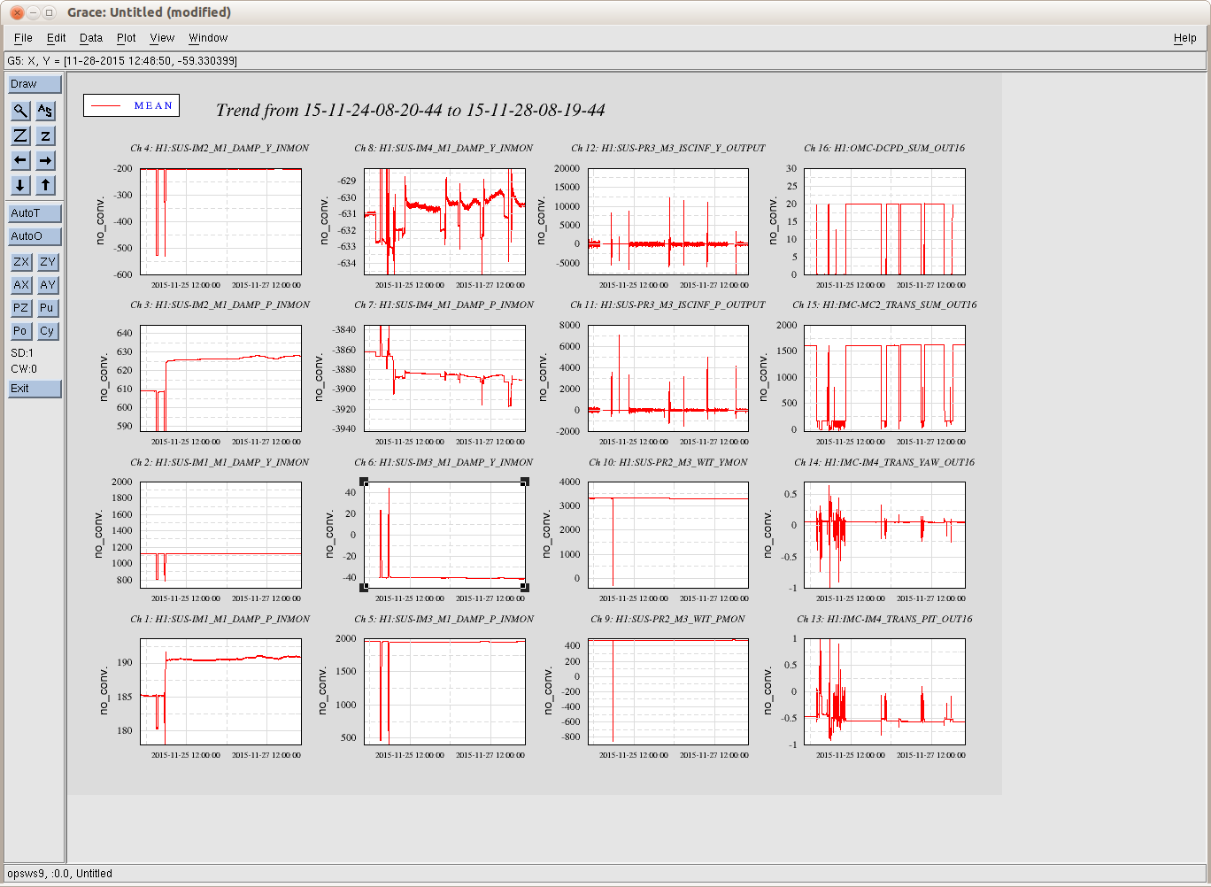
I believe I have moved IM1 and IM2 to there approximate positions before the HAM2 ISI trip (alog 23777). I moved IM1 in PITCH from 800 to 592. I moved IM2 in PITCH from 17980 to 17232.

I started an initial alignment. I got to the point where both ALS_XARM and ALS_YARM were at the INITIAL_ALIGNMENT state and was waiting for the ASC convergence. However when I got to GREEN_WFS_OFFLOADED the Y arm dropped in power. I am now struggling to bring it back.
Comments related to this report