This entry follows upon the entry 23167 where the frequency of the 3rd and 4th harmonic for the QUAD suspensions violin modes were identified. This entry is also complementary to Evan Hall's entry 22847 where similar Q's were measured with a different technique.
In this analysis, a line tracker (iWave) was applied over each of the identified 3rd and 4th harmonic frequencies (23167) on 21 hours of data during which the detector was continuously in Observing mode and with the damping filters turned off, data analysed started from 2015-10-21 21:30:00. The channel I used is H1:OMC-DCPD_SUM_OUT_DQ downsampled to 8192Hz in order to be able to handle the considerable ammount of data.
The line tracker was set to lock, on an automated way, to each of the monitored frequencies of interest. The tracker provides the frequency value which it is following and the amplitude of that frequency as a function of time. This information is provided in real time with the data being analysed. Although I automated the process the line tracker could not always lock to the mode of interest, in a few cases it locked to the wrong mode of higher amplitude and/or was not able to separate modes of high amplitude and close proximity. Therefore a targetted run had to follow the automated one.
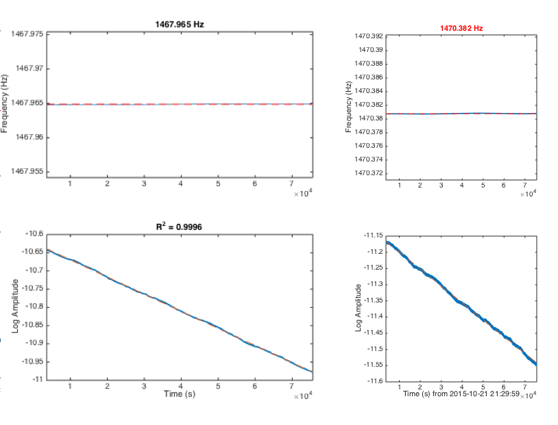
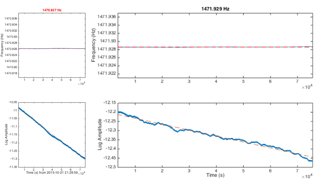
The result of the analysis is summarised on the attached 'png' plots which shows; in each column the mode monitored with the top plot being the frequency tracked as a function of time and the bottom plot the 'log(Amplitude)' (Napierian or natural logarithm of the mode's amplitude). The red dashed lines are respectively the median of the tracked frequency and the fitted first order polynomial to the 'log' of the mode's ringdown.
Notice that monitoring 21 hours at 8192Hz resolution of 50 modes provide a huge ammount of data so here I only present a summary of the results, and this is also the reason why the plots shown are .png files.
The first order polynomial fitting of the ringdown was done using Matlab's 'polyfit' function which implements a least-squares minimization fitting. This function also provides an estimate of the covariance matrix of the fitted coeficients which is used to calculate the standard error or variance of the estimated coeficients for the linear fit of the log(Amp) ringdown. In particular only the slope of the fitted line is used to estimate Q = Pi * f0 / abs(slope_fit), where f0 is the median of the frequency tracked. The median of the tracked frequency has an observed uncertainty smaller than 1mHz which makes the Q relative uncertainty to be dominated by the slope fitting uncertainty as given by the covariance matrix of the fitted coefficients. Therefore the reported error on Q will be given by the uncertainty of the slope of the fit as:
(Delta(Q) / Q)^2 = (Delta(slope_fit) / abs(slope_fit))^2
Next I summarise the results in 4 columns (also on attached .txt files labelled 'Q_results_3Harm_1stFreq_2ndQ_3rdDeltaQ_4thEHresults' and ''Q_results_4Harm_1stFreq_2ndQ_3rdDeltaQ_4thEHresults); first is the mode frequency, second is my estimated Q, third is the estimated Q error, and 4th is Evan Hall's results from 22847 for comparison:
Mode frequency (Hz) Q (line tracker) Delta(Q) Q_from_22847
1.0e+09 *
0.000001456177151 1.055261277139490 0.000021679047341 1.060000000000000
0.000001456842619 1.011674961643711 0.000024977780728 1.020000000000000
0.000001461409317 0.547106388691582 0.000007012695846 0.550000000000000
0.000001461732469 1.000243995219630 0.000121822842175 1.000000000000000
0.000001461859533 0.673721968942594 0.000056781365996 0.644000000000000
0.000001462031866 1.015448724742734 0.000039055044799 1.030000000000000
0.000001462313302 1.109264503070151 0.000020406518349 1.120000000000000
0.000001462596624 0.879503445780186 0.000090574514768 0.921000000000000
0.000001463096689 0.881010088452959 0.000383879344618 0.995000000000000
0.000001463100039 0.990987050813072 0.000431799209313 0
0.000001467475846 1.089361798635816 0.000107769329936 1.130000000000000
0.000001467964869 0.979770107952095 0.000024671825593 1.000000000000000
0.000001470380790 0.886560854120574 0.000042794470546 0.894000000000000
0.000001470826225 1.046162403099169 0.000070957888675 1.040000000000000
0.000001471928631 1.433692732321030 0.000246428147278 1.280000000000000
0.000001472216373 1.036874013551553 0.000319968824557 1.070000000000000
0.000001472450299 1.116249774693906 0.000012761989599 1.130000000000000
0.000001474079863 1.178125176004288 0.000086507667346 1.170000000000000
0.000001475097416 1.001120432026481 0.000377881305540 0.935000000000000
0.000001475251394 1.148066981481587 0.000155330486516 1.160000000000000
0.000001478169574 0.781717093501666 0.000095725814070 0.830000000000000
0.000001482585386 0.865266831531971 0.000049369138115 0.879000000000000
0.000001484077440 0.912365853159565 0.000100741959112 0.914000000000000
0.000001484430000 0 0 0.796000000000000
0.000001484525699 0.821953404180692 0.000053588794283 0.836000000000000
0.000001484668763 1.396430023353472 0.000359948050123 1.270000000000000
0.000001922925589 0.806732893457201 0.000050155023271 0.812000000000000
0.000001923612098 0.904079503131098 0.000101465317927 0.856000000000000
0.000001923854589 0.730146274074320 0.000057632970265 0.741000000000000
0.000001923861257 1.045943198261562 0.000286910927180 1.000000000000000
0.000001924673359 0.656777206317145 0.000037377872702 0.675000000000000
0.000001924914736 0.822610665784300 0.000055143089987 0.845000000000000
0.000001926240582 0.877913538609440 0.000041733066792 0.888000000000000
0.000001927465534 1.193131464187697 0.000196087122798 1.080000000000000
0.000001928461859 0.491982285283618 0.000060799517584 0
0.000001929312799 1.014511076625149 0.000491391979504 0.742000000000000
0.000001931573475 0.770986524485489 0.000120874236513 0.778000000000000
0.000001932139817 0.721080850064806 0.000077175334498 0.739000000000000
0.000001932335653 0.723984558093199 0.000083370684684 0.713000000000000
0.000001932612502 0.802178526483954 0.000016727734773 0.806000000000000
0.000001940322842 0.727877169848855 0.000210139484624 0.778000000000000
0.000001940663844 0.923330707711907 0.000027923601820 0.941000000000000
0.000001941349656 0.922491569137019 0.000274707300452 0.906000000000000
0.000001942174877 1.171274720414585 0.000377051759607 1.050000000000000
0.000001942390477 1.094325186350570 0.000475289691312 0
0.000001943777687 0.914373092200222 0.000483429769721 0
0.000001946732789 0.732800137163962 0.000093031972218 0.677000000000000
0.000001954459289 0.803950536039718 0.000153319383649 0
0.000001955921818 0.684755442755530 0.000143761779921 0
0.000001957335075 0.651607142944878 0.000091322052084 0
0.000001959023577 0.785016144699797 0.000093723756453 0
NOTE: Although there are not big differences in results with entry 22847 for the 3rd harmonics, however some difference is observed on the Q's of 4th harmonics, also 7 more modes are reported here for the 4th harmonics.


BT ion pump photos.