Summary: This work aims to understand the shape of the DARM sensing function as affected by mode mismatches and input power. It seems that the mismatches affect the detuning of the SRCL DOF, that is it affects the locking point, but not the shape of the DARM sensing funciton. However, the input power, which causes radiation pressure, has a bigger effect on it. If I do not include QUADsuspension option, then I get a flat response function regardless of the mismatch or the input power.
For the past week I have been studying the effect of SCRL DOF detuning (or sometimes I refer to it as offset) on the DARM readout using FINESSE.
In FINESSE, that is done by changing SRCL.DC, and looking at the transfer function from DARM.AC.i to AS.DC.o
The reason being to understand the measurement of the sensing function taken and show here.
My system include up to maxtem=4, QUADsuspensions, InitialLock > DARM_RF_to_DC.
Before we start doing that, let’s understand the error signal of SRCL DOF. This is read at POP45_I channel. The ideal tuning of this loop is SRCL.DC=90, that is the case where the carrier beam is anti-resonant in the SRC, while the sidebands are. At that detuning, the error signal is 0. However, since we do not have a perfect model, there is some mode mismatch between SRC and the arm cavities. This will inject some higher order modes carrier and sidebands into the SRC and that changes the locking point. Using the default cold state LHO model, the detuning at which the error signal is 0 is SRCL.DC=-90.4643
This is shown in the plot below (Error_signals_vs_detuning.pdf)
Let’s look at this offset as the mode mismatch changes. I adjust ITMlenses focal lengths and measure the mismatch between SRX and XARM cavities, and SRY and YARM cavities. I also have an amplitude detector to measure the power in the HG20/02 modes at the AS port, which might be partially resonant in the SRC due to its low finesse. (Detuning_vs_SRC_ARMS_mismatch.pdf)
On the x-axis is the SRY to YARM mismatch percentage, and on the y-axis is the SRX to XARM mismatch percentage. I’m not sure why there is such a big difference of mismatches in the default cold state model, but the qualitative behavior is what we need here.
The colors represent SRCL.DC offset while the numbers on each cell represent the power in the 2nd high order mode in W.
We notice that as the SRY to YARM mismatch gets closer in magnitude to SRX to XARM mismatch the offset decreases and goes towards 90, and the power in the 2nd HOM also gets smaller, which suggests that the presence of these modes affects the offset, as we would expect(see also This old technical note)
I believe the reason that the HOM gets smaller as the mismatches get closer together can be imagined similar to what the Michelson interferometer does to the fundamental mode for HG20/02 modes that are at the same phase, they cancel each other out at the AS port.
Finally, let us look at the DARM sensing function, which is our goal of this investigation.
We would expect the sensing function to be flat starting around ~7Hz and keep like that until it starts rolling off at ~ 200 Hz.
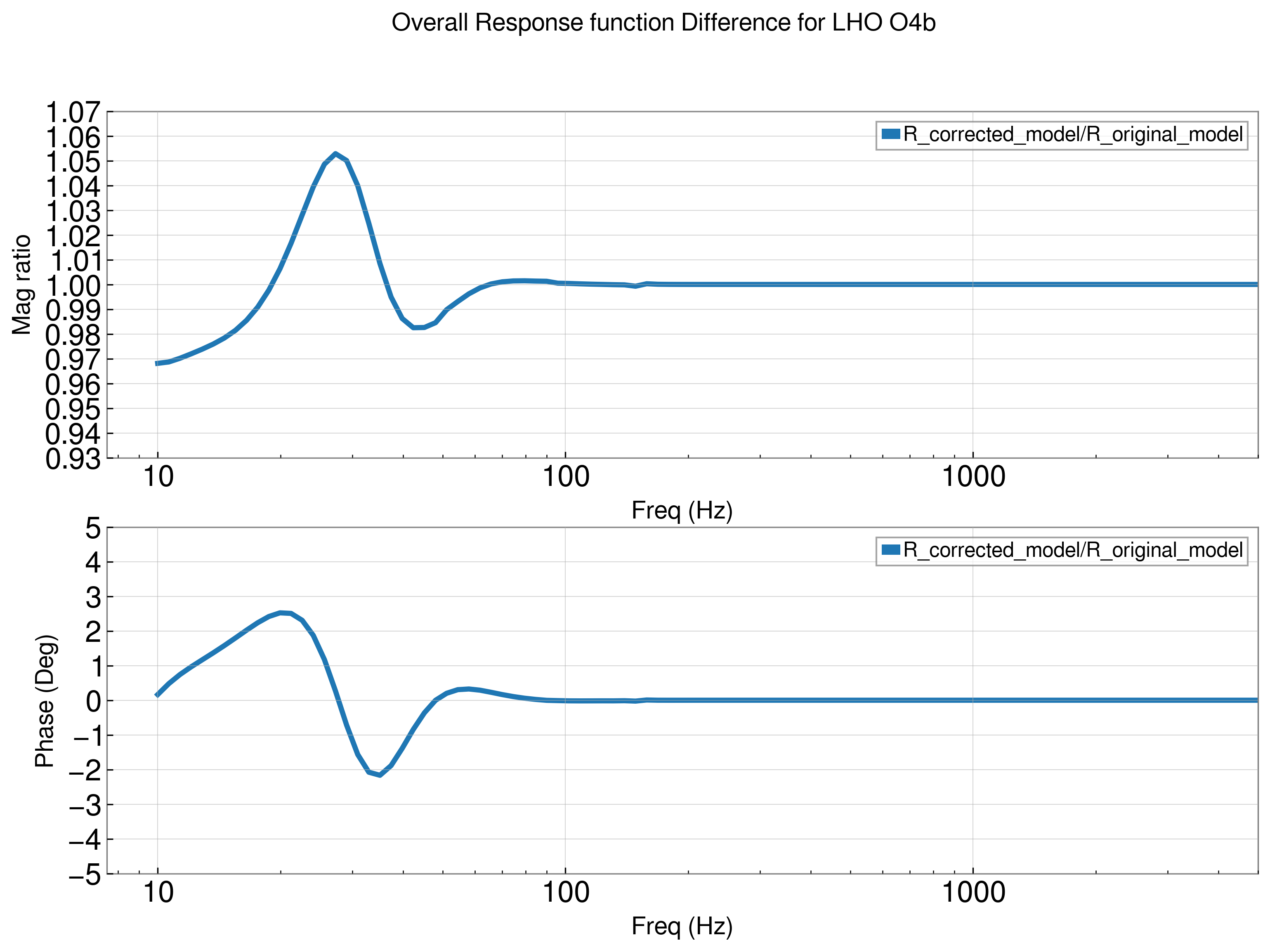
Now, here is the surprise, I plotted the response function in the default case where there is mismatch between SRC and the arm cavities, and then I changed ITMXlens focal lengths to get almost perfect mode matching, and it turns out that they are not that different, as seen below (Comparison_with_different_MM.pdf)
What seems to be affecting the response function is not the mode matching (even though it affects the locking point), but the input power value. If I reduce the input power to 1W instead of 60W that is used in the comparison plot, I get the following response function (yes, I checked the error signal zero point is still at 90.464 (1W_DARM_readout_vs_detuning.pdf)
And so, from this investigation, it seems that the input power affects the response function more than the mode matching, while the mode matching affects the locking point.
Next, I reset the model and I started changing the reflectivity of the SRM, narrowing the linewidth and increasing the finesse of the cavity. As the finesse increases, the detuning goes towards 90 degrees. This could be from reducing the effect of the HOM on the fundamental mode in SRCL. (SRM_reflectivity.pdf)