(Borja, Vinny Roma)
This is a continuation of the work started yesterday here. Today, during maintenance, we worked all morning on the hunting of the 60Hz glitch noise and we can now confirm that the issue was identified and solved.
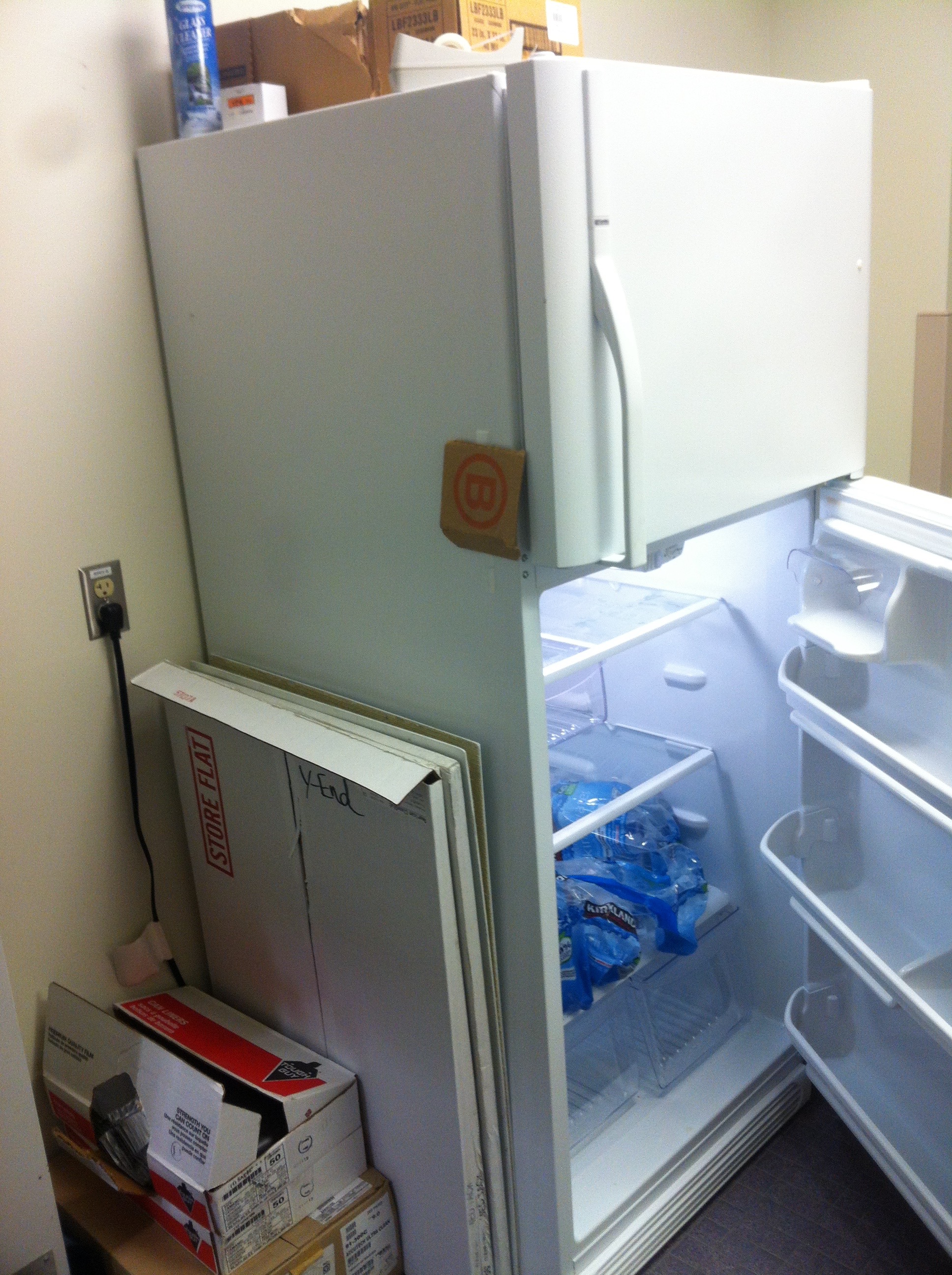
At 2015-11-17 17:10 (UTC) we arrived at the EndY station. We noticed an aircon unit outside of the building (although different model to that reported at Livingston) also used for cooling old clean rooms and no longer in use. We were sure that it was not running at the times that we observed the 60Hz bursts. We also noticed a fridge ON as we came in...more on this later.
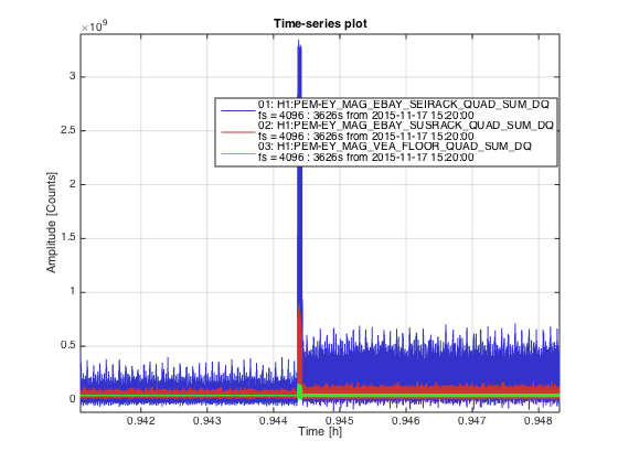
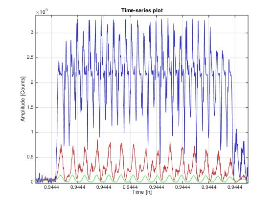
We carried portable magnetometers similar to the ones used at the sites but plugged into oscilloscopes for portability. The area we concentrated most of our noise hunting was the electronics bay (EBAY) as from previous measurements we noticed that the bursts were stronger at the magnetometers located there (MAG_SUSRACK and MAG_SEISRACK) in comparison with MAG_VEA (see attached figure 'Comparison_MAGs_QUAD_SUM.png'). Looking at the spikes in more detail (see 'Zoom-spikes_Mag_VEA_and_EBAYs.png') we observe that while the spikes in MAG_VEA has a frequency of 60Hz, the spikes on MAG_EBAY_SUS and MAG__EBAY_SEI has double the frequency. This seems to be cause to a non-linear response of the transducer to the magnetic field, stronger in MAG_SEI than in MAG_SUS as both are identical sensors we assume the magnetic field from the spike is stronger at the SEI magnetometer.
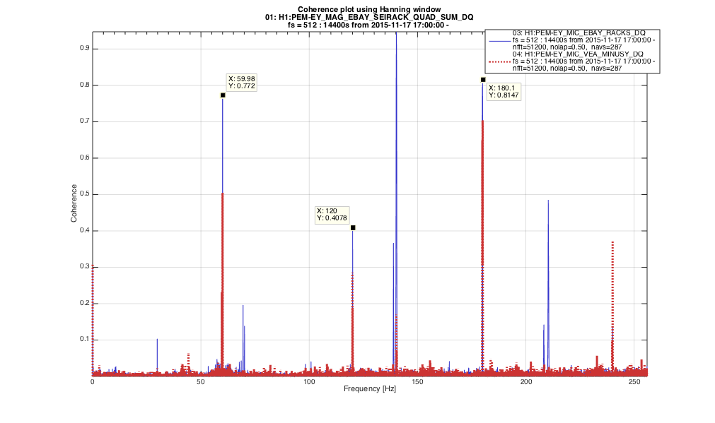
Another clue that pointed to EBAY as the area of interest is the coherent plot attached of the MIC_EBAY and MIC_VEA_MINUSY with MAG_EBAY_SEI, we can clearly see correlations at 60Hz and harmonics being always stronger at MIC_EBAY. Notice however that we were never able to hear the burst so we assume the microphones pick them up electromagnetically.
In order to confirm that the bursts were actually real signals (instead of rack related issues) we swapped the axes of both magnetometers on EBAY as we observed they had different signal strenght. The change in the observed signal strength after the swap was compatible with the axes changes. Notice that we undid these changes after the morning work, so now is all back to normal.
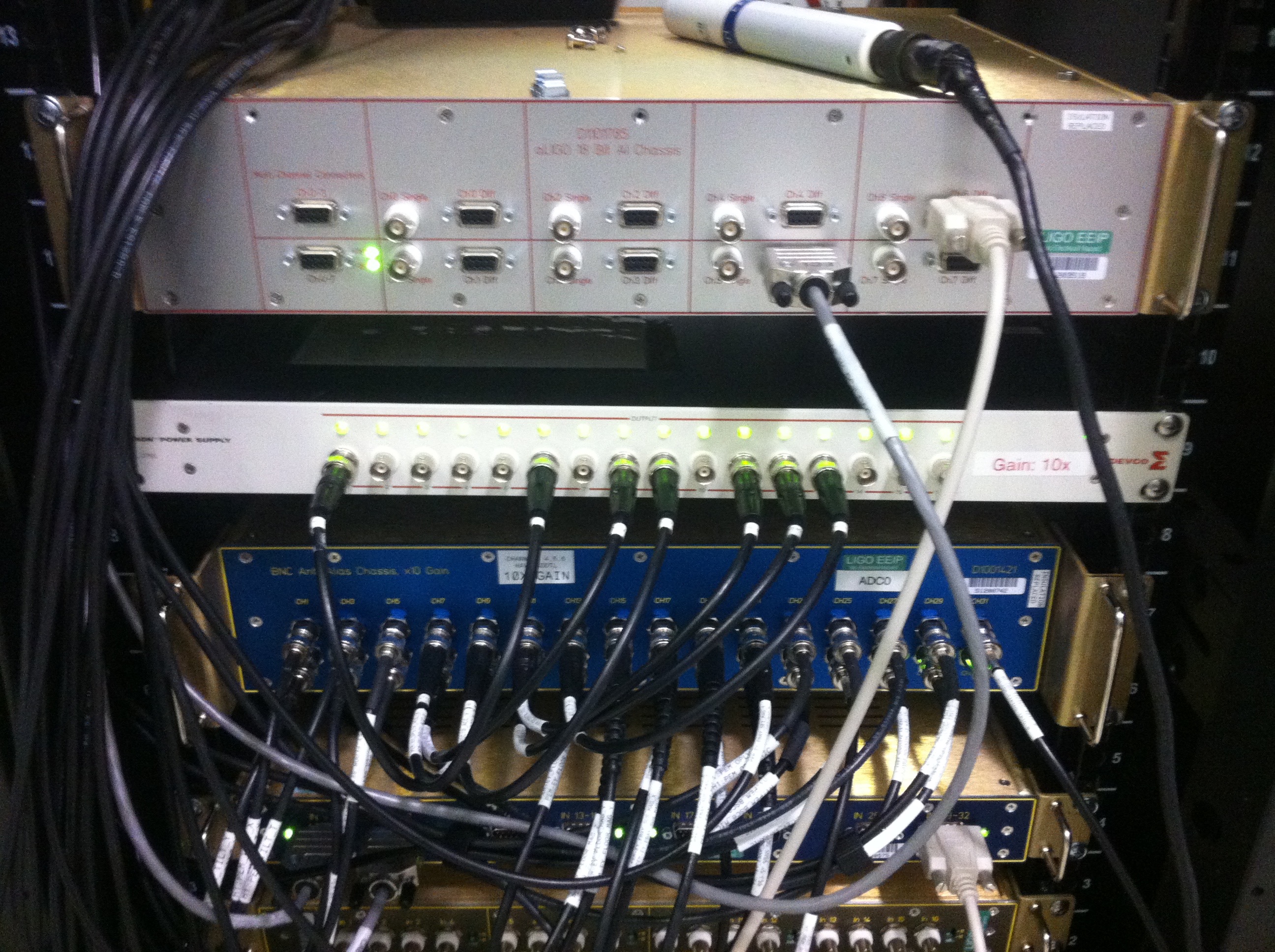
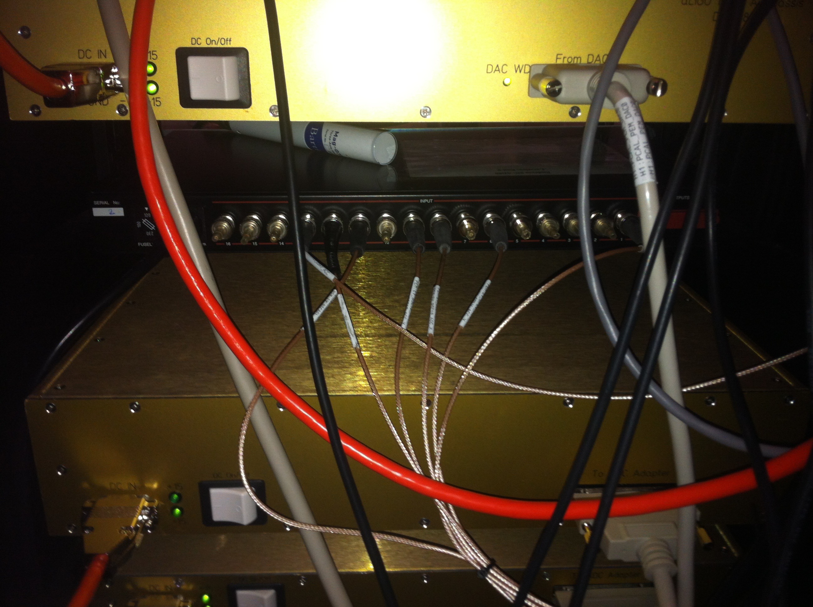
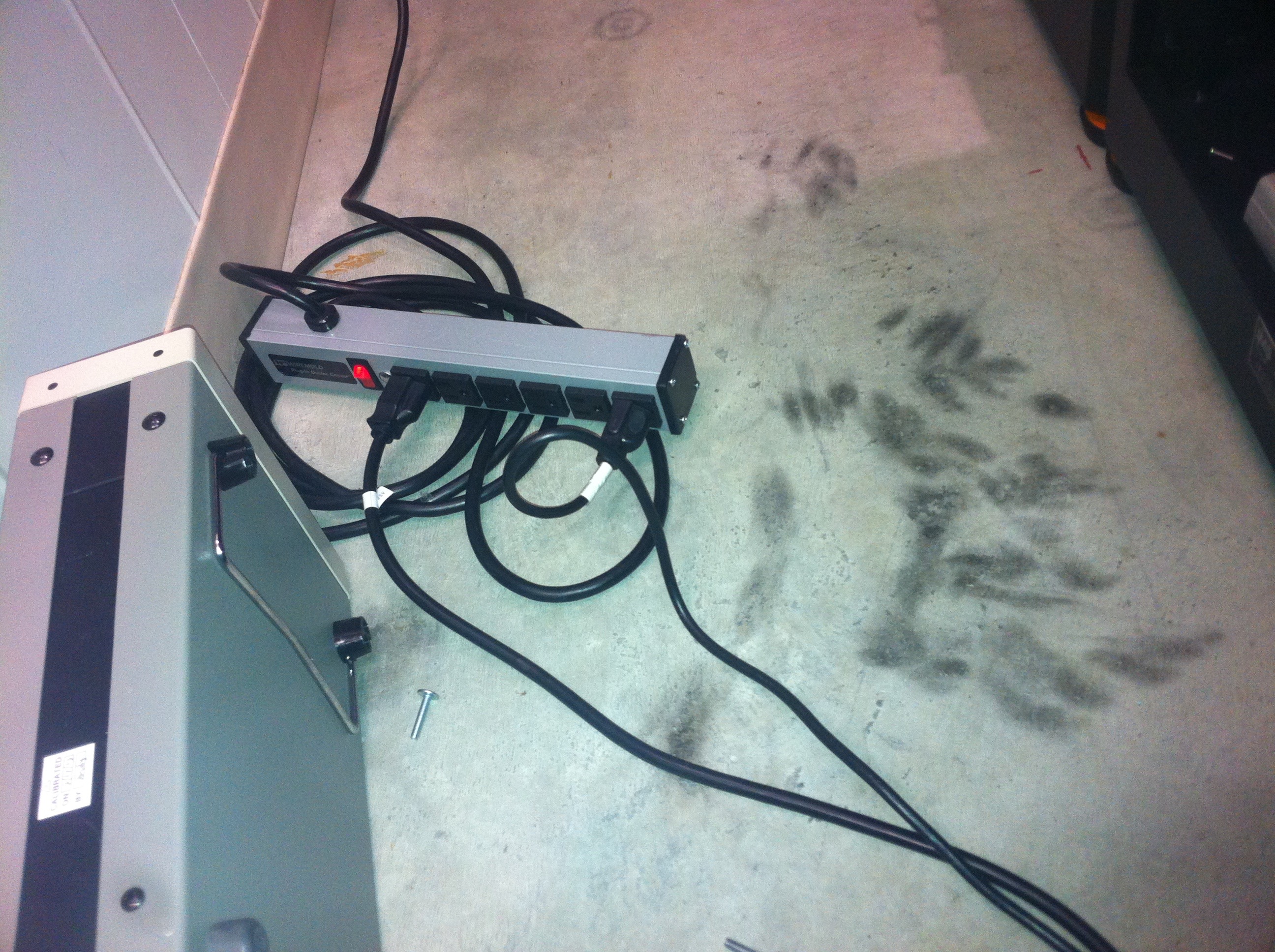
Then we moved the portable magnetometer around the EBAY racks and noticed no strong magnetic noise anywhere with the exception of the 'PEM Endevco Power supply' which powers the accelerometers. The magnetic field around this box was very strong and MAG_EBAY_SEI is not far away from it. We also noticed that this was the only device connected to the wall AC power supply (see attached pictures) and this is also the case anywhere this PEM power supply is used.
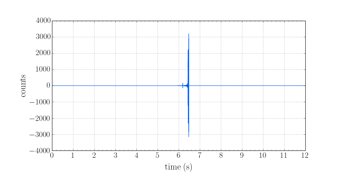
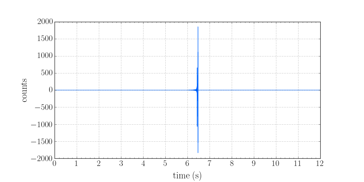
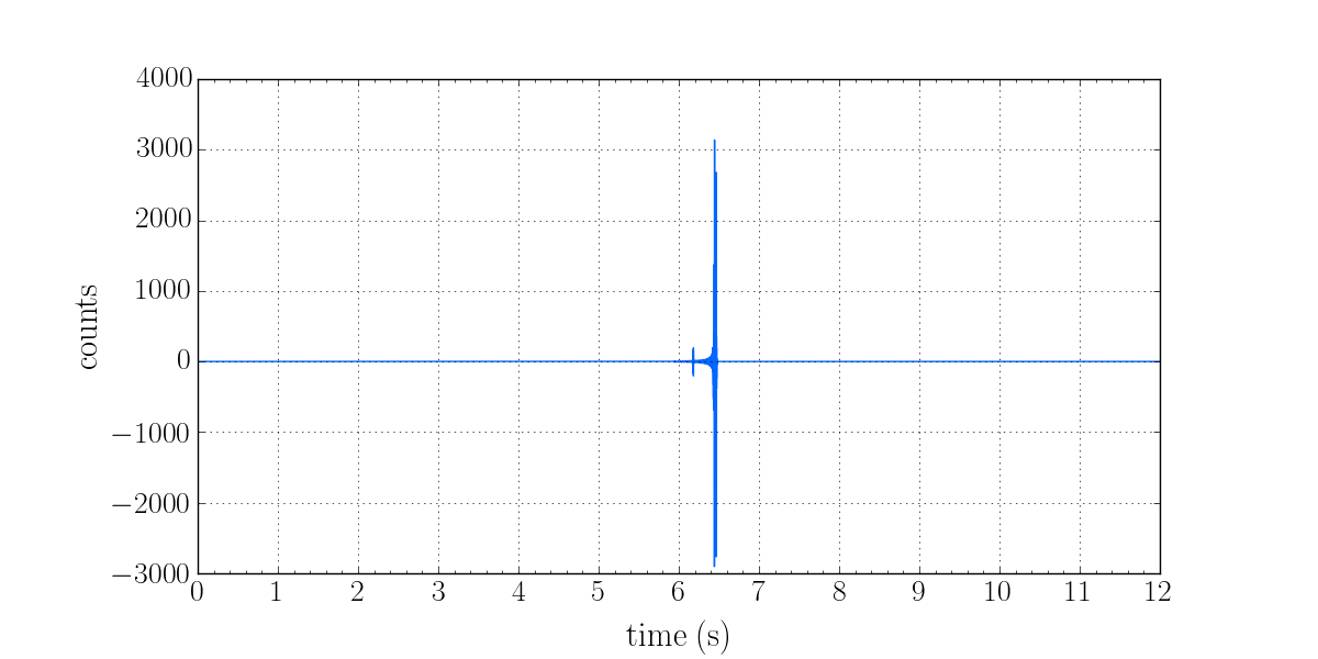
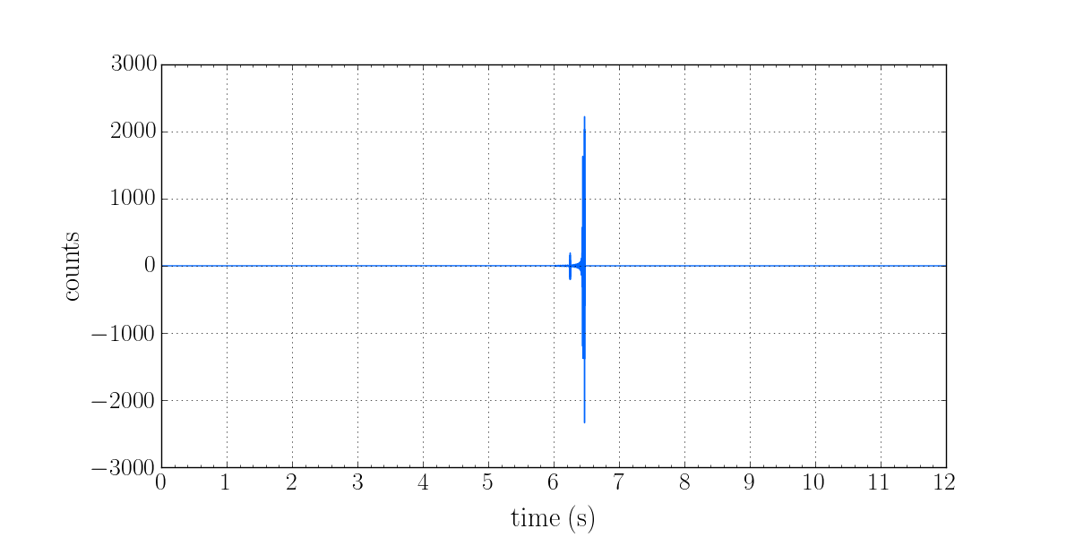
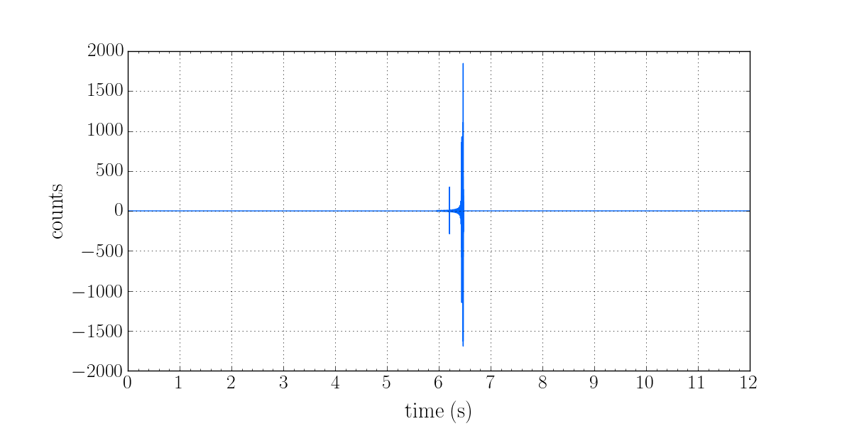
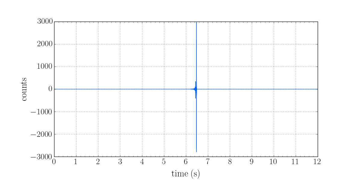
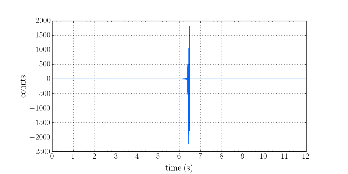
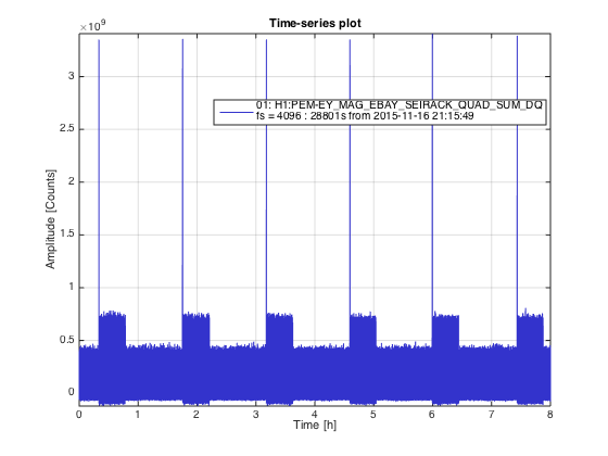
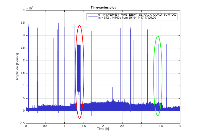
We attach a time plot of EY_MAG_EBAY_SEI during the whole morning working period and we can see several things:
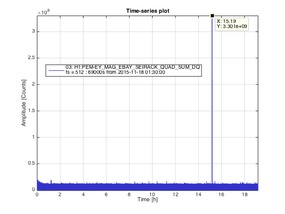
1) The time interval between bursts is much shorter and less regular than before (this was also observed previously when work was done at the End station). Compare attached plots from yesterday night ('Latest-60Hz_Bursts', very regular 85minutes separation between spikes) and today ('Morning_60Hz_timeplot_MAG', totally irregular with as short separation as 3 minutes).
2) The burst structure is different than the one previously related to 60Hz glitch noise (see here). For instance see the red circled area. During this time the vacuum cleaner was on near EBAY.
At this point we realized human activity with electric devices plugged to the wall at the station was involved with the generation of 60 Hz bursts although with a different signature to the bursts we knew and came to hunt.
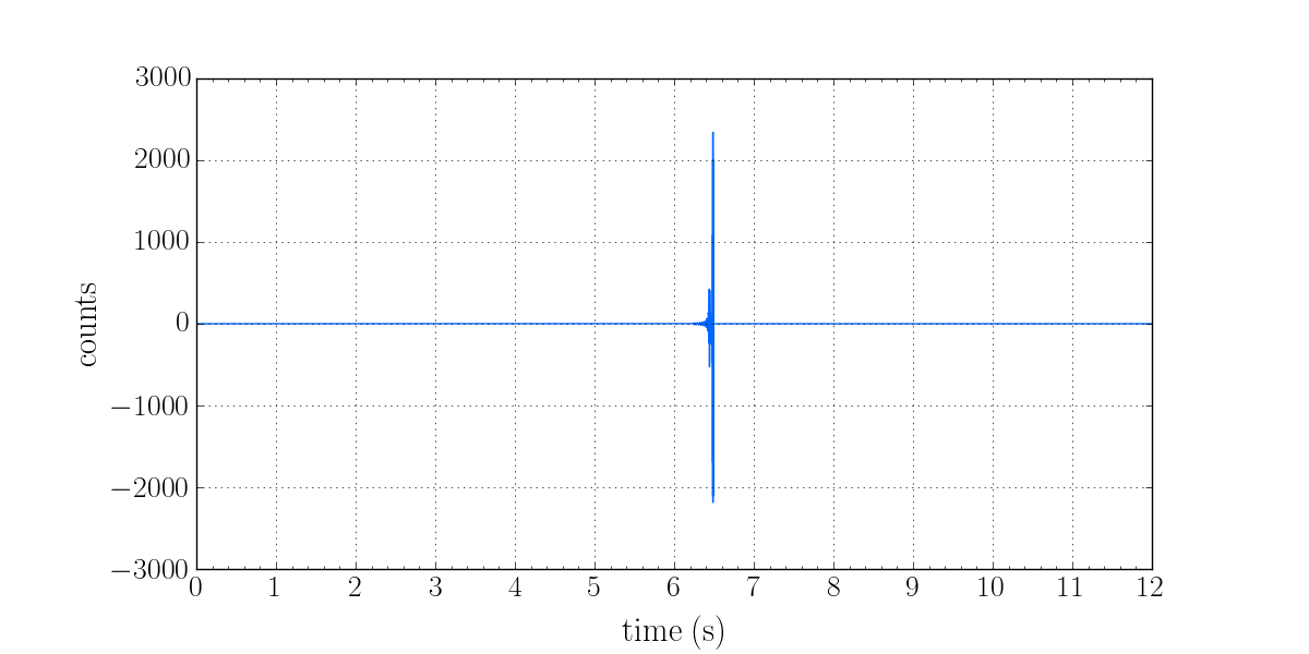
Suddently for almost an hour (between hours 1.7 and 2.5 in plot 'Morning_60Hz_timeplot_MAG') we saw nothing. Then the burst became more spaced so after a while we tried to reproduce the vacuum cleaner burst signature by switching it on. The vacum cleaner was in the same room as the fridge and we noticed that the fridge was now turned OFF (we later learned that John and Bubba turned it OFF).
Then everything started to make sense...the fridge compresor only needs to be on when the temperature inside the fridge drops below a threshold which it can happen every 1.5 to 2 hours or longer depending on the environment temperature and quality of the fridge insulation. Notice that the interval between burst was shorter in summer than current months. Then the compresor is usually on for a few tens of minutes until the temperature is winthing desired range and then the compresor turns off. So in order to confirm the fridge as the cause of our 60Hz burst and glitches we tested turning it ON and we saw a burst (circled green on the previous plot at hour 3.5). And as we turned it OFF then the 60Hz burst dissapeared.
It appears that the fridge was ON the whole O1, this will no longer happen. But notice that any device drawing current from the mains seem to generate 60Hz bursts at least picked up by the magnetometers in EBAY, so soon we thought that maybe this is relared with the only device in that room that is plugged to the mains and that has a considerable Magnetic contamination...the 'PEM Endevco Power supply'.
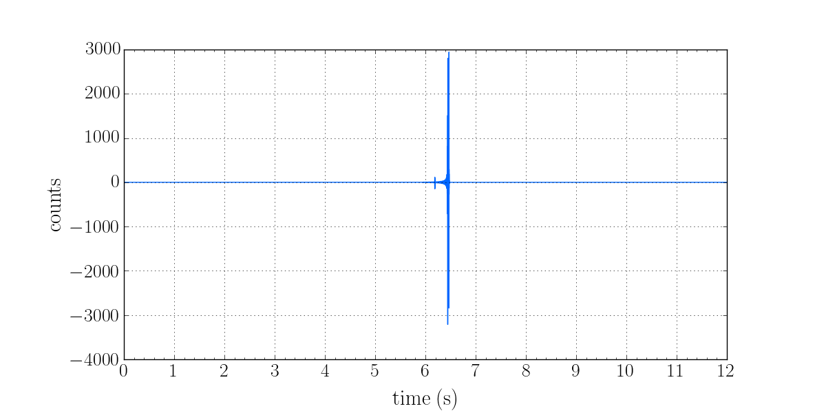
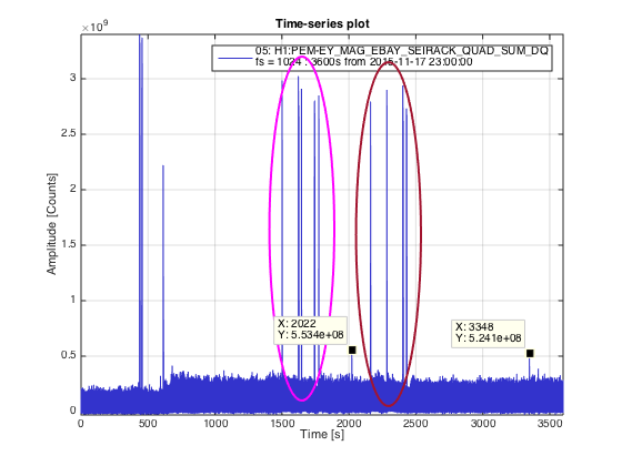
So after lunch we went back to EndY station (arriving at UTC 23:07:00) with the intention of checking if unplugging the PEM Power Supply from the wall would be enough for the EBAY magnetometers not seeing the current draw by the fridge as this was turned on and off on 1 minute intervals for 3 times. For comparison we did the same test before with the Power supply still plugged and turned on. Unfotunatelly we see no difference between these two cases on MAG_EBAY_SEI as per attached plot 'Checking_PEM_Power_Supply_Coupling.png' magenta circle is with PEM Power Supply ON and brown is with the Power supply OFF. Interestingly however we can see a small spike at about UTC (23:34:00) when the turned off the Power supply and at 23:55:00 when we turned it back on.
Notice the spikes at the beginning correspond to our arrival to End station probably due to switching ON the shoe cleaner at the entrance and the desktop computer at EBAY.