Summary
Q: What is the relationship between the strength of violin mode ring-ups and the number of narrow spectral artifacts around the violin modes? Is there a clear cut-off at which the contamination begins?
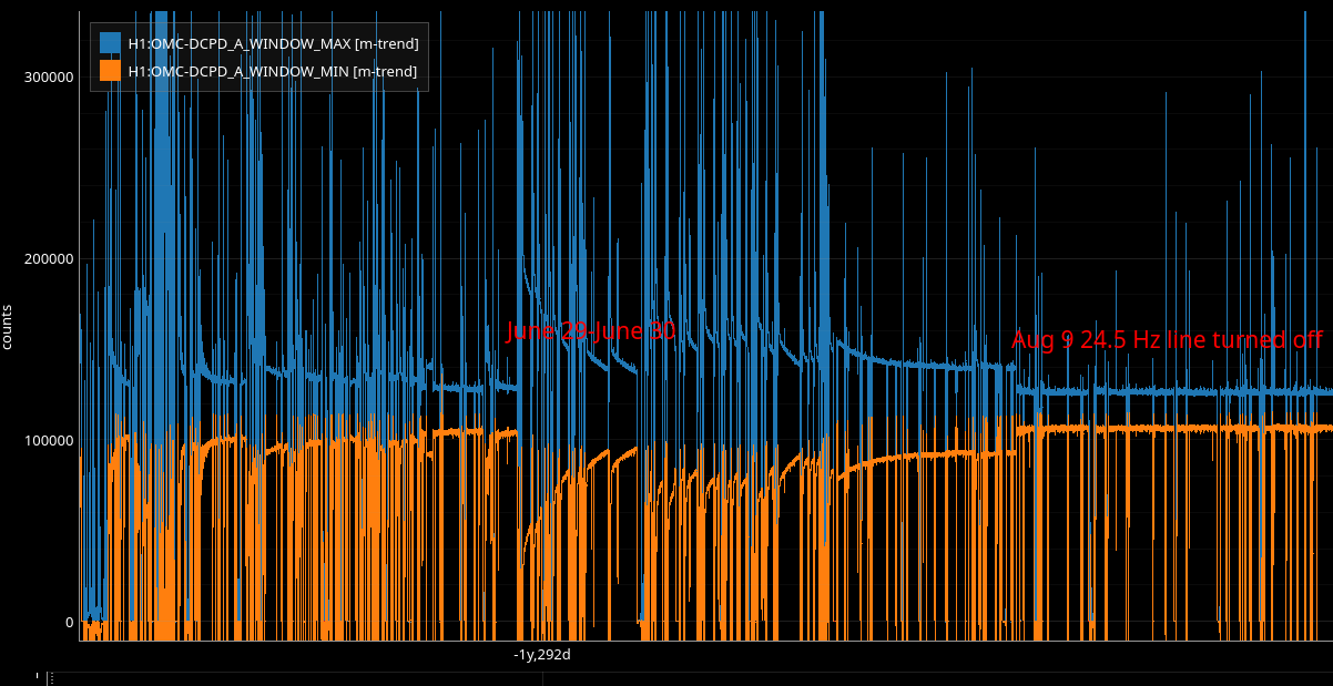
A: The answer depends on the time period analyzed. There was an unusual time period spanning from mid-June 2023 through (very approximately) August 2023. During this time period, the number lines during ring-ups was much greater than in the rest of O4, and the appearance of the contamination may have begun at lower violin mode amplitudes.
What to keep in mind when looking at the plots.
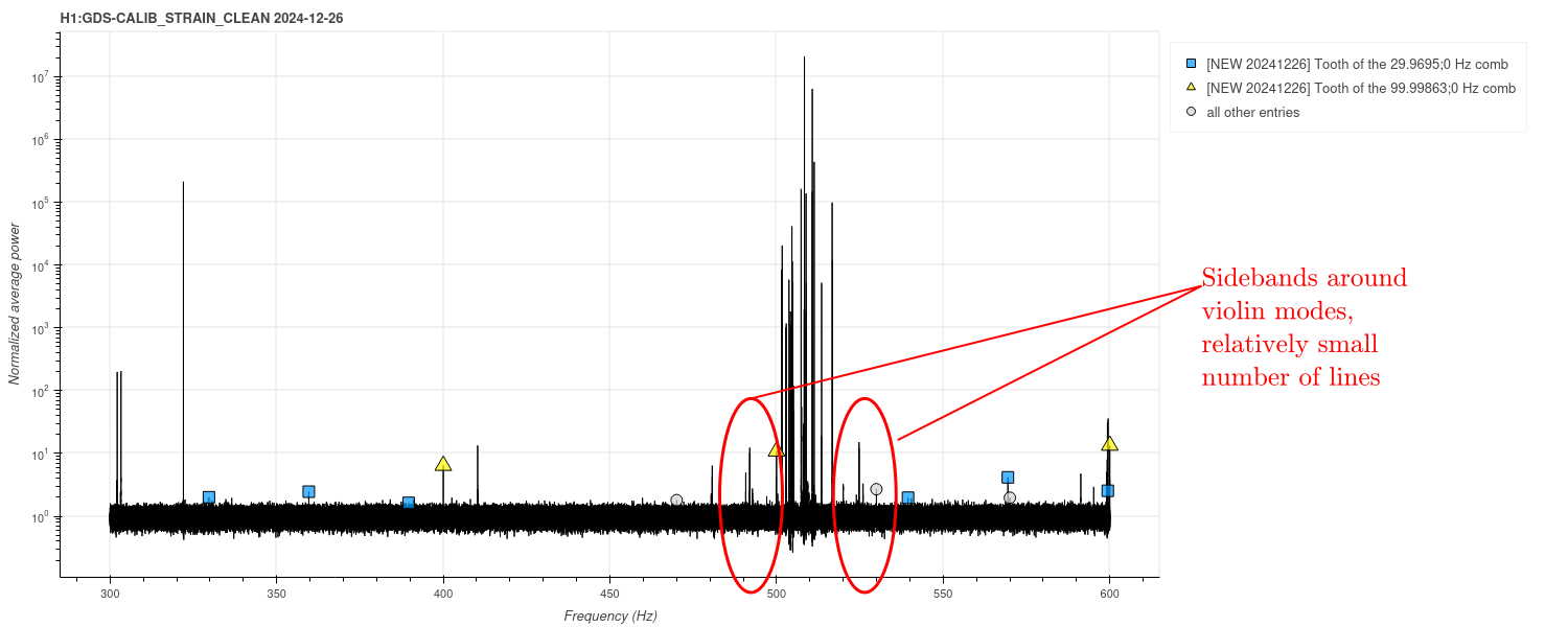
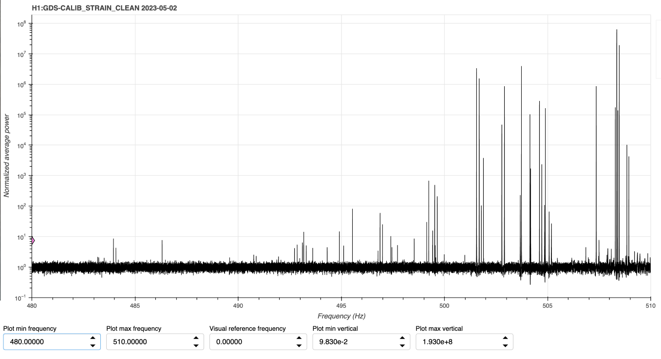
1. These plots use the Fscan line count in a 200-Hz band around each violin mode region, which is a pretty rough metric, and not good for picking up small variations in the line count. It's the best we've got at the moment, and it can show big-picture changes. But on some days, contamination is present, but only in the form of ~10 narrow lines symmetrically arranged around a high violin mode peak. (Example in the last figure, fig 7) This small jump in the line count may not show up above the usual fluctuations. However, in aggregate (over all of O4) this phenomenon does become an issue for CW data quality. These "slight contamination" cases are also particularly important for answering the question "at what violin mode amplitude does the contamination just start to emerge?" In short, we shouldn't put too much faith in this method for locating a cut-off problematic violin mode height.
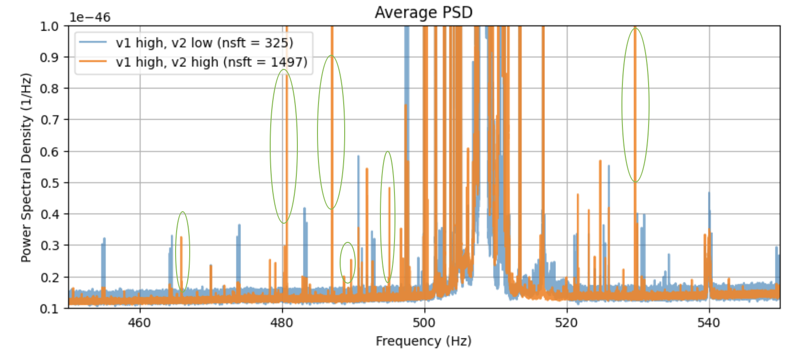
2. The violin modes may not be the only factor in play, so we shouldn't necessarily expect a very clear trend. For example, consider alog 79825 . This alog showed that at least some of the contamination lines are violin mode + calibration line intermodulations. Some of them (the weaker ones) disappeared below the rest of the noise when the violin mode amplitude decreased. Others (the stronger ones) remained visible at reduced amplitude. Both clusters vanished when the temporary calibration lines were off. If we asked the question "How high do the violin modes need to be...?" using just these two clusters, we'd get different apparent answers depending on (a) which cluster we chose to track (weak or strong), and (b) which time period we selected (calibration lines on or off). This is because at least some of the contamination is dependent on the presence & strength of a second line, not a violin mode.
Looking at the data
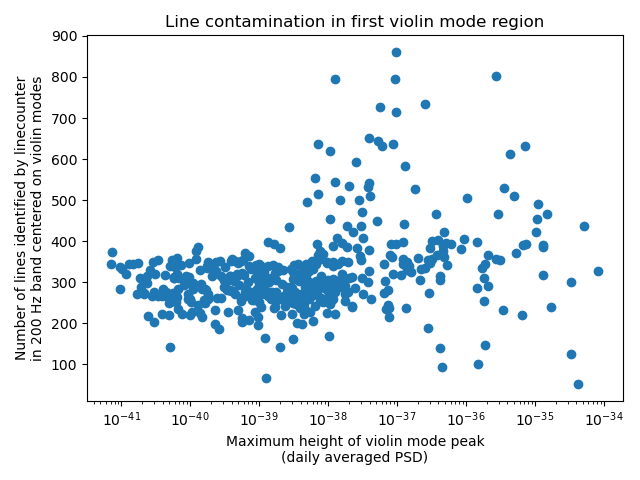
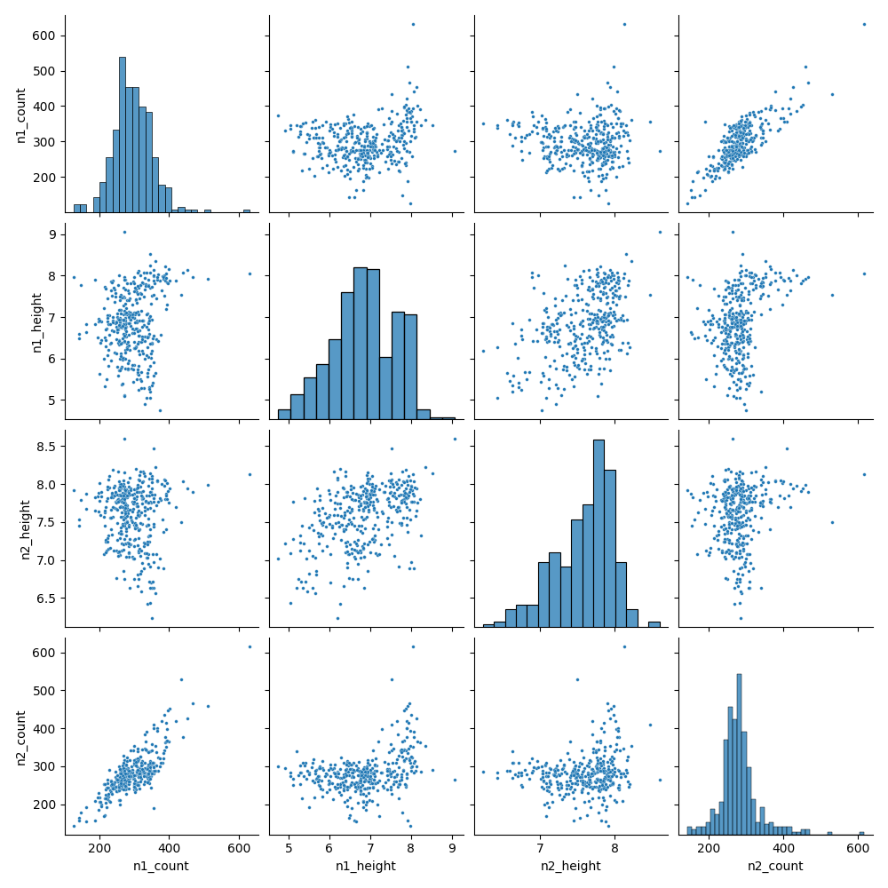
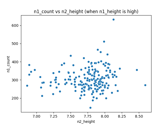
First, let's take a look at a simple scatter plot of the violin mode height vs the number of lines identified. This is figure 1. It's essentially an updated version of the scatter plots in alog 71501. It looks like there's a change around 1e-39 on the horizontal axis (which corresponds to peak violin mode height).
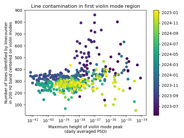
However, when we add color-coding by date (figure 2), new features can be seen. There's a shift at the left side of the plot, and an unusual group of high-line-count points in early O4.
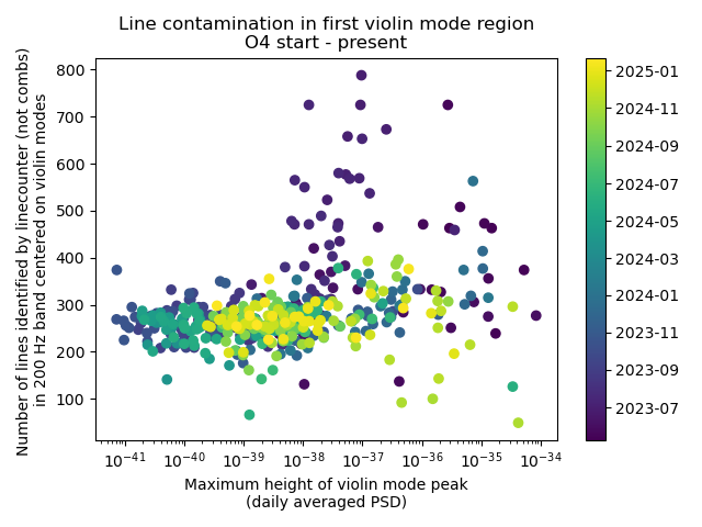
The shift at the left side of the plot is likely due to an unrelated data quality issue: combs in the band of interest. In particular, the 9.5 Hz comb, which was identified and removed mid O4, contributes to the line count. Once we subtract out the number of lines which were identified as being part of a comb, this shift disappears (figure 3).
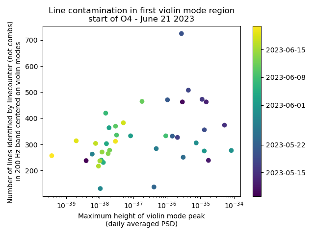
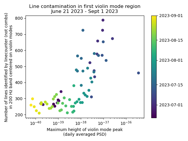
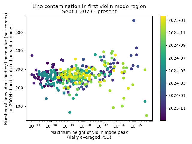
With the distracting factor of comb counts removed, we still need to understand the high-line-count time period. This is more interesting. I've broken the data down into three epochs: start of O4 - June 21, 2023 (figure 4); June 21, 2023 - Sept 1 2023 (figure 5); and Sept 1 2023 - present (figure 6). As shown in the plots, the middle epoch seems notably different from the others.
These dates are highly approximate. The violin mode ring-ups are intermittent, so it's not possible to pinpoint the changes sharply. The Sept 1 date is just the month boundary that seemed to best differentiate between the unusual time period and the rest of O4. The June 21 date is somewhat less arbitrary; it's the date on which the input power was brought back to 60W (alog 70648), which seems a bit suspicious. Note that, with this data set, I can't actually differentiate between a change on June 21 and a change (say) on June 15th, so please don't be misled by the specificity of the selected boundary.