thomas.shaffer@LIGO.ORG - posted 11:27, Wednesday 11 November 2015 - last comment - 12:31, Wednesday 11 November 2015(23310)
Lockloss
Lockloss @ 19:22
Lockloss @ 19:22
LLO is down with some "high" winds. Chris Biwer will run a swept sine while there is an opportunity.
WP#5595
Beginning swept-sine test for CAL-INJ while LLO is down.
Swept-sine for 500-2000Hz began at 18:55:45 UTC and finished. Lost lock at 19:23 UTC.
To do the swept sine from 500-2000Hz I used the template at: https://svn.ligo.caltech.edu/svn/aligocalibration/trunk/Runs/O1/H1/Measurements/INJ/template_cw_inj_sweptsine_500to2000_20151111.xml

I've attached the coherence and TF from CAL-INJ_CW_EXC to CAL-DELTAL_EXTERNAL_DQ.

Attached is a summary of PEM injections, with summary plots for both sites, estimates of environmental contributions to DARM and calibrated coupling factors. These are also useful for calculating the SNR in DARM from the SNR in the PEM channel, determining coupling sites for environmental events in DARM, and for comparing coupling between LHO and LLO. Links to the individual reports follow.
Magnetic
LHO: https://alog.ligo-wa.caltech.edu/aLOG/index.php?callRep=21272
LLO: https://alog.ligo-la.caltech.edu/aLOG/index.php?callRep=20599
RF
LHO: single f’s https://alog.ligo-wa.caltech.edu/aLOG/index.php?callRep=23252
sweep https://alog.ligo-wa.caltech.edu/aLOG/index.php?callRep=22968
LLO: preliminary single f’s https://alog.ligo-la.caltech.edu/aLOG/index.php?callRep=20599
Vibration
LHO: https://alog.ligo-wa.caltech.edu/aLOG/index.php?callRep=22797
LLO: https://alog.ligo-la.caltech.edu/aLOG/index.php?callRep=22463
Site activities
LHO: https://alog.ligo-wa.caltech.edu/aLOG/index.php?callRep=21272
LLO: https://alog.ligo-la.caltech.edu/aLOG/index.php?callRep=20599
Robert, Anamaria
Travis brought it all the way up, We are now in Observing. Winds <15mph, Seismic: 0.03-0.1Hz = 0.02um/s, 0.1-0.3 = 0.8um/s. The PSL power was 21.8W a second ago, but seems to have come up to 22.1W since I started writing this. LLO is also up and Observing.
TITLE: "Day DAY Shift: 16:00-00:00UTC (08:00-16:00 PDT), all times posted in UTC"
STATE Of H1: Almost locked
OUTGOING OPERATOR: Travis
QUICK SUMMARY: Winds and seimic kept the previsou shifts down, but seemed to have died down 30min ago so Travis has the IFO almost all the way locked for me.
Title: 11/11 Owl Shift 7:00-15:00 UTC (0:00-8:00 PST). All times in UTC.
State of H1: Lock acquisition
Shift Summary: Wind dropped like a rock at ~15:00 UTC. I began an initial alignment since it had been down for 4 hours and had been through a windstorm. Microseism is trending up but still at a manageable level.
Incoming operator: TJ
Activity log:
8:33 GRB alert, LLO was down
12:03 Adjusted X and Y arm ALS fiber polarization
15:42 Chris to X arm for beam tube sealing
Still down after the lockloss earlier due to high winds. Winds are in the 30s with gusts to over 40 mph, and the forecast predicts it won't get better for the rest of the day. But who believes the weathermen anyways?? (According to the NWS, they are off by a factor of 2 in their prediction at the moment, however in the wrong direction for GW science. It is supposed to be 15 mph with gusts to 20.)
I had to call Keita at 4am PST to walk me through an ALS fiber polarization adjustment since I had never done one and could not find a procedure to do so (it is on my list to add to the OPS Wiki). The wind did its typical thing where it calms just enough to lull you into the sense that you should begin locking again before it picks back up. Sorry Keita, you should sleep in this morning or get a nice breakfast or something.
Lockloss, most likely due to winds which are gusting to over 50 mph.
Activity Log: All Times in UTC (PT)

00:00 (16:00) Take over from TJ
02:40 (18:40) First of four large (mag 6.9 to 4.9) EQs in Chile. All four arrived within 30 minutes.
05:00 (21:00) Start initial alignment
06:19 (22:19) IFO locked at NOMINAL_LOW_NOISE, 22.1w, 78Mpc
06:24 (22:24) Cleared SDF and set intent bit to Observing
06:56 (22:56) Lockloss – mag 5.2 EQ on Mid-Pacific Ridge
07:30 (23:30) Relocked at NOMINAL_LOW_NOISE, 22.2w, 78mpc
	      No SDF differences flagged – Set Intent bit to Observing
08:00 (00:00) Hand off to Travis


End of Shift Summary:

Title: 11/10/2015, Evening Shift 00:00 – 08:00 (16:00 – 00:00) All times in UTC (PT)

Support: Keita, Betsy, Hugh, Vern, Marissa

Incoming Operator: Travis

Shift Summary: Had problems locking the ALS green, mostly in X. Keita found the BSC-9 ISI had a large swing on the X platform location. (See #23293). The motion slowed down, and I was able to realign the ALS green for both arms. Tried relocking. Made it to DARM_1F before 4 large EQs hit Chile. Seismic motion is very high right now (See #23296). Waiting for things to settle and will try relocking.

After seismic activities settled down to below 0.1 um/s and microseism dropped to 0.3 – 0.2 um/s, ran initial alignment. The IFO was locked at NOMINAL_LOW_NOISE. Cleared up several SDF issues, and set the intent bit Observing. Wind at the CS is a moderate breeze (13 – 18 mph) and light to gentle (4 – 12) at the ends and mids.

Lockloss due to Mid-Pacific Ridge Earthquake. Seismic activity has rung up a bit, but is quickly coming down. Microseism did not change from 0.3 um/s. Wind is up to a fresh breeze (19 – 24 mph) in the CS. The wind at the ends and mids is still light to gentle breeze (4 – 12 mph). Will attempt to relock without doing an initial alignment.

IFO relocked easily without the need for a realignment. Back to Observing
The SDF diffs that Jeff accepted were from the dark offset scripts that I ran at 23:28 UTC.
   IFO is not locked.

   Between the maintenance activities, problems with a swinging BSC-9 ISI (#23293), and a nine large EQs in Chile, locking has been unsuccessful.

   After the motion of BSC-9 settled down, I did an ALS realignment, and was able to get the IFO to DRMI_1F, before the first two Chilean EQs (mag 6.9 & mag 6.6) arrived. Low frequency seismic activity jumped up to over 10 um/s, microseism was over 1 um/s.

   There were at least nine large earthquakes in Chile (mag 6.9 to mag 4.8) within a one hour period. Things are starting to calm down. Will give it a bit more time to settle down and them will redo initial alignment.

   At least the wind is just a light breeze (4 -7 mph).
  While relocking at ~ 02:10 (18:10) the seismic plot jumped up to plus 3.0 um/s and microseism went to plus 1.0 um/s. They started to come down when they again both rung up. Seismic plot is at 11.0 um/s and microseism went from 0.7 um/s to back over 1.0 um/s.

  There was a 6.6 mag EQ and a 6.9 mag EQ in Chile (R-Wave arrival ~ 02:40 (18:40)), a 4.9 EQ mag in Chile (R-Wave arrival ~ 03:04 (19:04)) and a 5.1 mag EQ in Chile (R-Wave arrival ~ 03:09 (19:09)).

   Not much chance for relocking until the seismic activity calms down.
People were having problem with relocking after the maintenance.
IMC VCO tune offset was railing at +-5V whenever COMM PLL was trying to enable slow feedback to IMC. TJ manually disabled it, not sure why this was turned on, it seems like the guardian does not touch this.
When both X and Y were unlocked, it was clear that X arm fringe velocity was much much larger than Y arm just by looking at the camera.
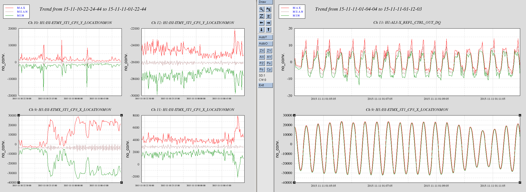
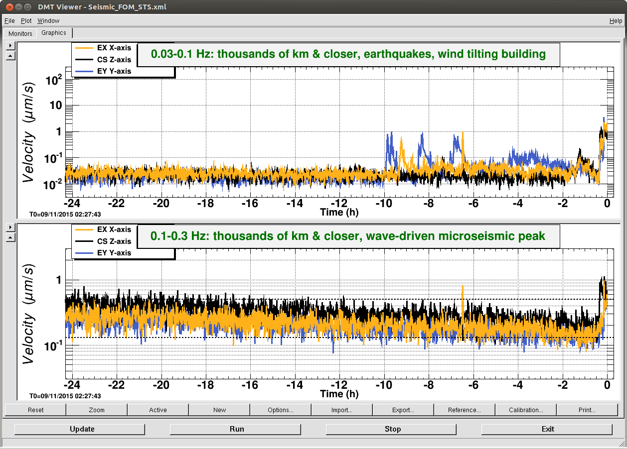
It seems like the EX ISI has been going crazy for the past 2 hours or so (first attachment left). I haven't checked if this is due to ground motion, It seems like the FOM for 0.03-0.1Hz band shows us that there's something going on (but EY looks noisier) (second attachment).
The dominant frequency of the noise is about 1/24 Hz, so the frequency is about right (first attachment right).
As I was talking to Jeff, however, ETMX ISI slowed down. We'll see.
(Update: As we were waiting, we are hit by another quake at around 2:10 or so UTC.)
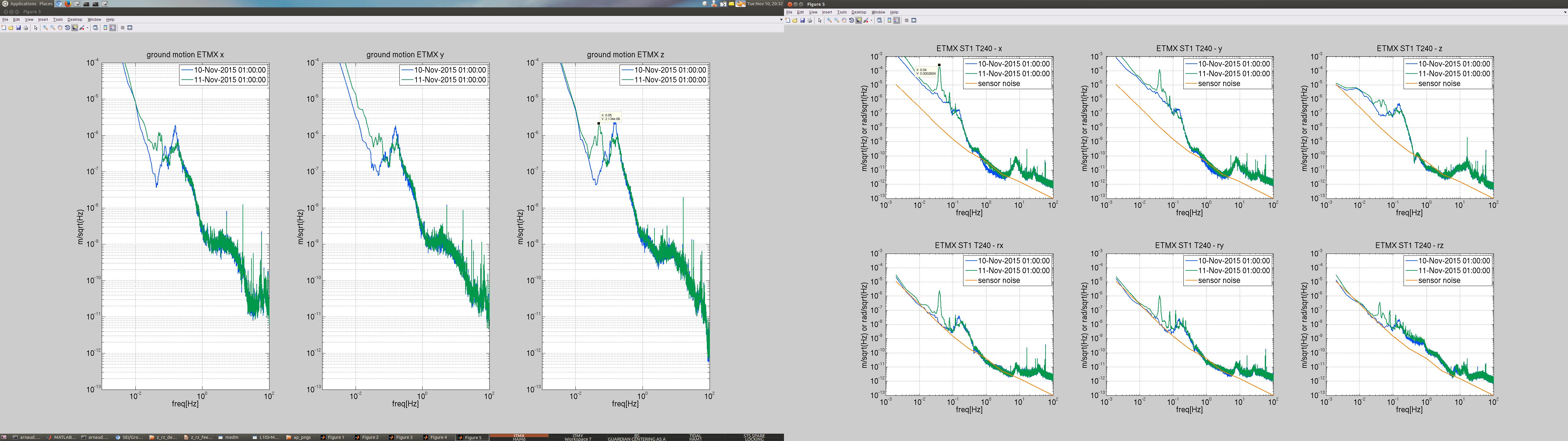
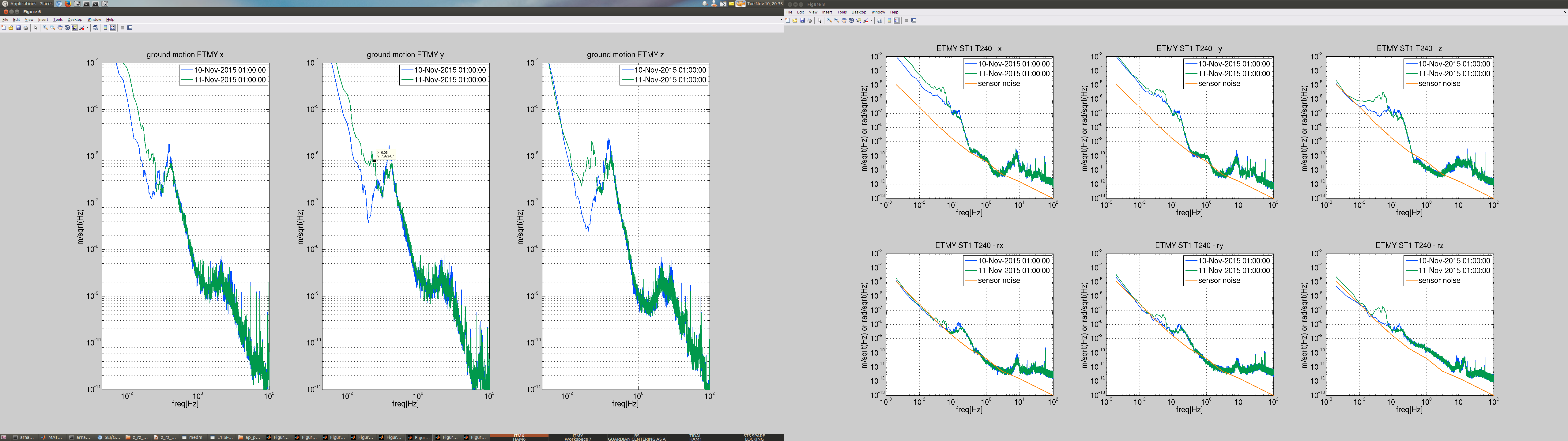
Attached is a spectra comparing the ground motion between yesterday and today -EX first image, EY second image-. There is certainly 50mHz elevated motion, compared to yesterday.
Although it is strange how large is the ETMX motion on stage 1 at 40mHz, witnessed by the t240. Certainly much more than for EY.
Looking at the transmissibility at EX from ground to stage 1 -image 3- , it seems the motion is much more amplified (compared to yesterday) between hepi and stage 1 in x and y, cf green in 2nd row.
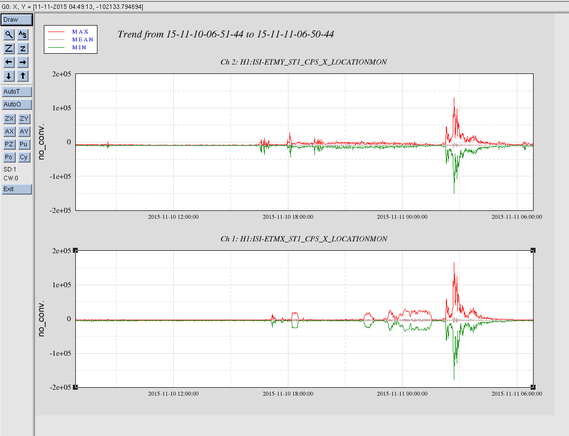
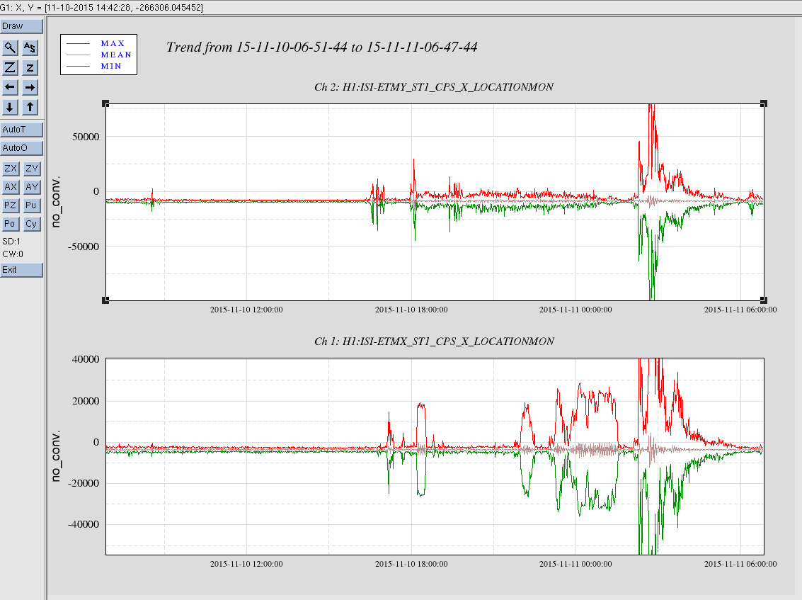
Took 24 hour plots of the ETM-X and ETM-Y ISI CPS X locations covering the time of the problems with ETM-X.
Title:  11/10/2015, Evening Shift 00:00 – 08:00 (16:00 – 00:00) All times in UTC (PT)

State of H1: 00:00 (16:00), The IFO is unlocked. Recovering from maintenance window

Outgoing Operator: TJ

Quick Summary:  Working on relocking after the Tuesday maintenance window.
Turns out the answer is 'very easily'. I tested by opening testpoints with dataviewer and dtt (aka diaggui). The have different behaviour, with dataviewer generally doing the right thing and dtt doing the wrong thing.
The tests are
1: open the application, open the testpoint, logout of the computer, log back in.
2: open the application, open the testpoint, power down the computer using the power button, power the computer back up, log back in
Dataviewer:
Test 1, once the user loged out, the testpoint was cleared. PASS
Test 2, after the machine was powered down, the test point was stuck on. FAIL. When the computer was powered back on and before the user logged back in, the test point was cleared. PASS?
DTT:
Test 1, after logout the testpoint was stuck on, had to manually clear it. FAIL
Test 2. after power down testpoint was stuck on (even though h1nds1's log showed an "about the clear' message). FAIL. After computer restarted test point still stuck on. FAIL.
So DTT users can easily leave stuck test points if they dont cleanly exit their dtt sessions before logging out or powering down.
I believe in the old days there was a timeout feature, but it would take a while.
We have been running tinj so that it injects transient hardware injections into CAL-INJ_TRANSIENT_EXC.

I updated tinj to use CAL-PINJX_TRANSIENT_EXC, this is the hardware injection excitation channel that uses PCAL.

The procedure was:
  (1) Edit tinj.m to use CAL-PINJX_TRANSIENT_EXC
  (2) Stop tinj using the monit web interface
  (3) Compile run_tinj using the command (note I did not source anything into my env): mcc -R -nojvm -R -nodisplay -R -singleCompThread -m run_tinj
  (4) Commit changes to SVN
  (5) Restart tinj using the monit web interface

I tailed tinj.log and it was updating as expected. And checked that the run_tinj process was running with both monit and top.
tinj was updated at LLO as well. See: aLog entry

Both sites will now inject into CAL-PINJX_TRANSIENT_EXC.
I couldn't open up any new medm windows. Everything else seemed to be working fine though. I killed the sitemap process and restarted it, but this did not fix the issue. After the reboot it all worked well.
It seems like this work station in particular has been having issues lately...
Had the same problem occur around 01:00 (17:00). Closed all open applications and powered cycled terminal. Informed Dave & Carlos.

Possibly due to the injection testing. Everything else seemed calm. Attached the generic Lockloss tool set of plots.