edmond.merilh@LIGO.ORG - posted 14:50, Sunday 08 November 2015 (23219)
GRB Alarm
22:36UTC IFO very glitchy and Livingston not locked.
22:36UTC IFO very glitchy and Livingston not locked.
Andy, Jordan
There has been extreme glitchiness and range drops since the beginning of the current lock. Thought to be caused by the recurring RF45 issue.
Spectrograms comparing GDS-CALIB_STRAIN and the control signal:
https://ldvw.ligo.caltech.edu/ldvw/view?act=getImg&imgId=107526
https://ldvw.ligo.caltech.edu/ldvw/view?act=getImg&imgId=107525
a bit delayed, but 21:42UTC
MID-SHIFT SUMMARY: Still trying to get IFO aligned after eq activity calming down. µSeism is still high ≈.9microns. Kiwamu on site to help.
Details can be found here: https://wiki.ligo.org/viewauth/DetChar/DataQuality/DQShiftLHO20151102

Summary:

Duty Cycle: 68.4%,45.75%	 and 47.55% (Ignored last two locks of 4th, affected by RF45 noise) respectively.
- Range varied between 75-80 Mpc
- Glitch rate increased at the end of 3rd's lock. Last to locks of 4th Nov are ignored.

-EY Magnetic Glitches
Periodic 60Hz magnetic glitches are still present and are vetoed out using the channel PEM-EY_MAG_VEA_FLOOR on 2nd, 3rd and 4th.

-Loud Glitches
The Loud glitches are still there.

-RF45 Glitches
Some issue related to RF45 noise was noticed after 18:00 UTC on 4th November. There were few efforts to fix this issue. The details can be found in these alogs -23120, 23119

-Low Frequency Glitches
Low frequency cluster of glitches are present over the weekdays starting from ~13:00 UTC (end of day light saving time). HVeto is able to veto them out using the corner station seismic channels (Related alog and subsequent comments) . Laura/TJ noticed that each time 10-30Hz BLRMS channel crosses the threshold of 600nm/s, a cluster of glitches can be noticed in DARM (Related alog- 22494,22710).  DQ Flag details: https://wiki.ligo.org/DetChar/DataQuality/O1Flags#H1:DCH_45ISI_ITMY_Z_BLRMS_10_30_GT600:1

- Mainsmon Glitches
Loud SNR glitch rate increased significantly for the last couple of hours of 3rd November. HVETO  has used PEM-EY_MAINSMON_EBAY_QUAD_SUM channel to veto out these glitches at round 1. Corner station seismic channels also have huge significance drop  at the round 1 of HVETO. Related alog: 23113
This morning during down time I clamped the heavy EM shakers on the blue cross beams of HAMs 5 and 6. We think that HEPI and ISI will keep the alignment, as for previous shakers, but these are about 4 times as heavy.
TITLE: 11/08 [OWL Shift]: 08:00-16:00 UTC (00:00-08:00 PDT), all times posted in UTC
STATE Of H1: Aligning
SHIFT SUMMARY: Lost lock after earthquakes. Tried initial alignment starting with IR. Lost lock at ENGAGE_ASC_PART_3. Trouble staying locked on ALS. Started initial alignment from beginning. Waiting for ALS to converge.
Got timing error on h1iopacs0. Cleared with diagnostic reset.
Earthquake band has come back down to between 0.01 and 0.1 um/s. Microseism is still very high between 0.3 and 1 um/s.
Winds have subsided to below ~ 10 mph.
INCOMING OPERATOR: Ed
TITLE: Nov 8 DAY Shift 16:00-23:00UTC (08:00-04:00 PDT), all times posted in UTC
STATE Of H1: Locking
OUTGOING OPERATOR: Patrick
QUICK SUMMARY: IFO is unlocked due to a series of earthquakes. µSeism is exceeding 1micron! It’s going to be a fun-filled interactive morning, it looks like. Doing initial alignment.
Lost lock at ENGAGE_ASC_PART_3. Now having trouble staying locked on ALS.
Starting initial alignment from beginning.
Diag reset cleared it.
Done
Waiting for seismic from earthquakes to subside. Two jumps in 0.03 - 0.1 Hz seismic band to 1 um/s.
Earthquakes have subsided but winds have come up and microseism is still high.
SUS E_T_M_Y saturating (Nov 8 11:06:27 UTC)
SUS B_S saturating (Nov 8 11:06:27 UTC)
SUS I_T_M_X saturating (Nov 8 11:06:27 UTC)
Intention Bit: Commissioning (Nov 8 11:06:27 UTC)
ISC_LOCK state: DOWN (Nov 8 11:06:35 UTC)
DRMI Unlocked (Nov 8 11:06:35 UTC)


Appears to be an earthquake. Jump to ~ 0.5 um/s in 0.03 - 0.1 Hz seismic band.
TITLE: 11/08 [OWL Shift]: 08:00-16:00 UTC (00:00-08:00 PDT), all times posted in UTC
STATE Of H1: Observing @ ~ 79 MPc.
OUTGOING OPERATOR: Nutsinee
QUICK SUMMARY: From the cameras the lights are off in the LVEA, PSL enclosure, end X, end Y and mid X. I can not tell if they are off at mid Y.
Earthquake seismic band is between ~ 0.01 and 0.1 um/s. Microseism has been steadily increasing and is now between ~ 0.3 and 1 um/s.
Winds are between ~ 5 and 15 mph.
ISI blends are on 45mHz.
TITLE: "11/07 [EVE Shift]: 23:00-07:00UTC (16:00-00:00 PST), all times posted in UTC"
STATE Of H1: Observing at ~80 Mpc
SUPPORT:
SHIFT SUMMARY: Microseism has been increasing over the past 20 hrs, now reaching 1 um/s. Wind picked up speed but died down shortly after. We got no trouble there. No noticable earthquake during this shift. Hardly any glitches.
INCOMING OPERATOR: Patrick
ACTIVITY LOG:
00:01 Ed to VPW to use air compressor.
00:31 Robert has been doing HVAC injections. see alog23198.
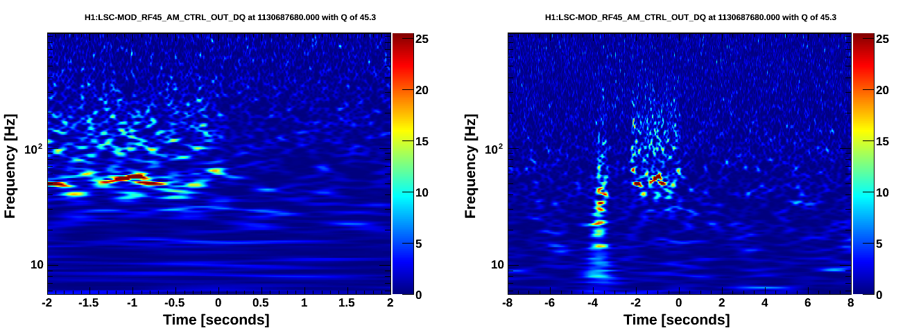
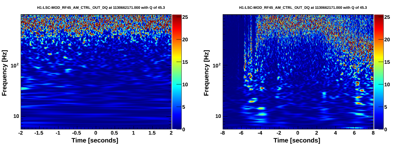
In the omiscans for the top 10 BBH/BNS triggers at the Hanford detector, there were three times that were startlingly noisy. The first can be seen here in the CALIB_STRAIN channel, with a good glitch correspondence picked out in the auxiliary channels:

https://ldas-jobs.ligo-wa.caltech.edu/~jacob.broida/Nov4/BBH/GW/1130687680/
https://ldas-jobs.ligo-wa.caltech.edu/~jacob.broida/Nov4/BBH/1130687680/#H1:ASC-REFL_A_RF45_Q_PIT_OUT_DQ

A quick look at the other auxiliary channels shows an unusual amount of strong noise. The following two scans, however, went even more haywire:

https://ldas-jobs.ligo-wa.caltech.edu/~jacob.broida/Nov4/BBH/GW/1130662168/
https://ldas-jobs.ligo-wa.caltech.edu/~jacob.broida/Nov4/BBH/1130662168/

https://ldas-jobs.ligo-wa.caltech.edu/~jacob.broida/Nov4/BNS/GW/1130662171/
https://ldas-jobs.ligo-wa.caltech.edu/~jacob.broida/Nov4/BNS/1130662171/

As of yet we are still unsure about the cause of all this noise.
These are caused by the known problem with the RF45 modulation. The clue is in the behavior of all the RF45 channels, but the decisive diagnostic is a scan of H1:LSC-MOD_RF45_AM_CTRL_OUT_DQ. This channel should normally be just noise, but will have bursts matching DARM when this problem occurs.
Looks like something changed at ~16:40 UTC