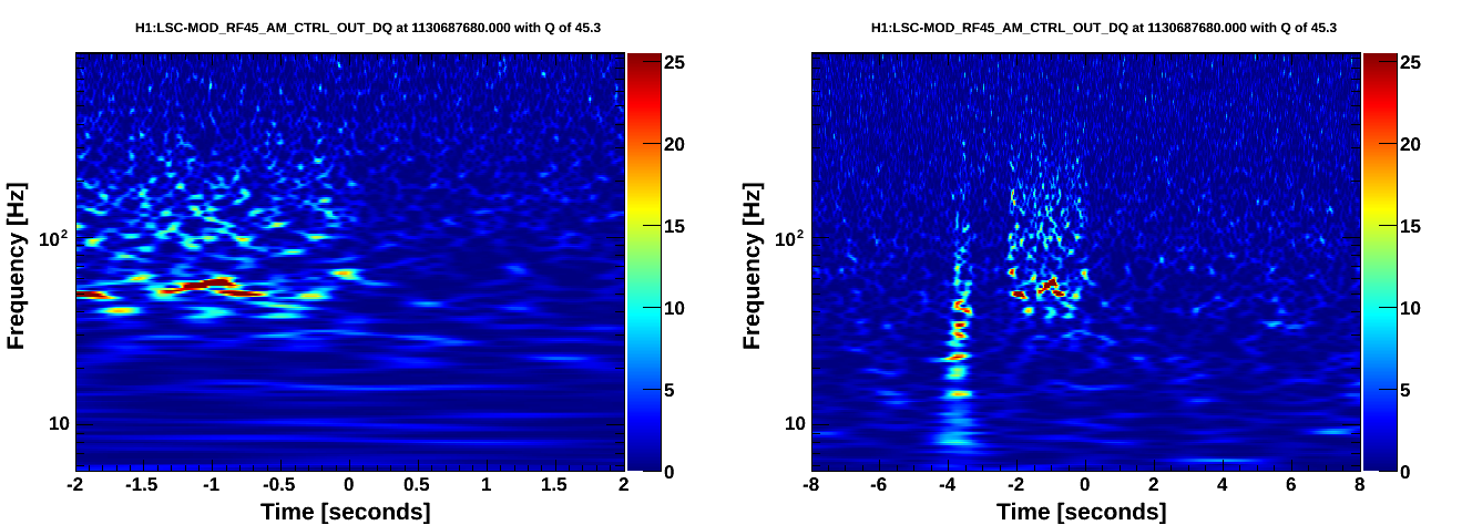
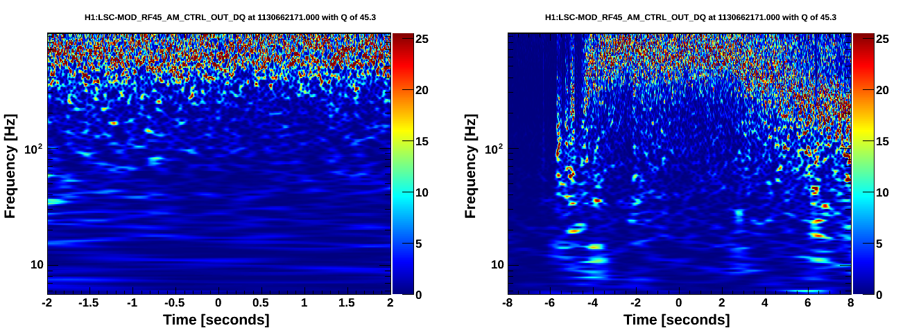
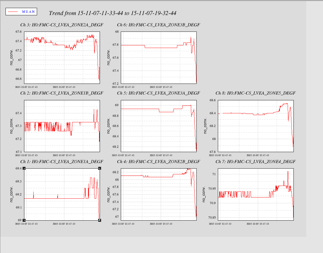
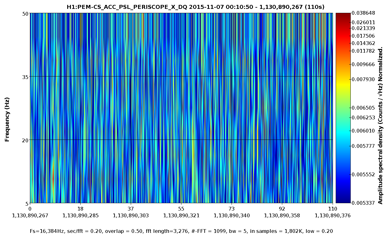
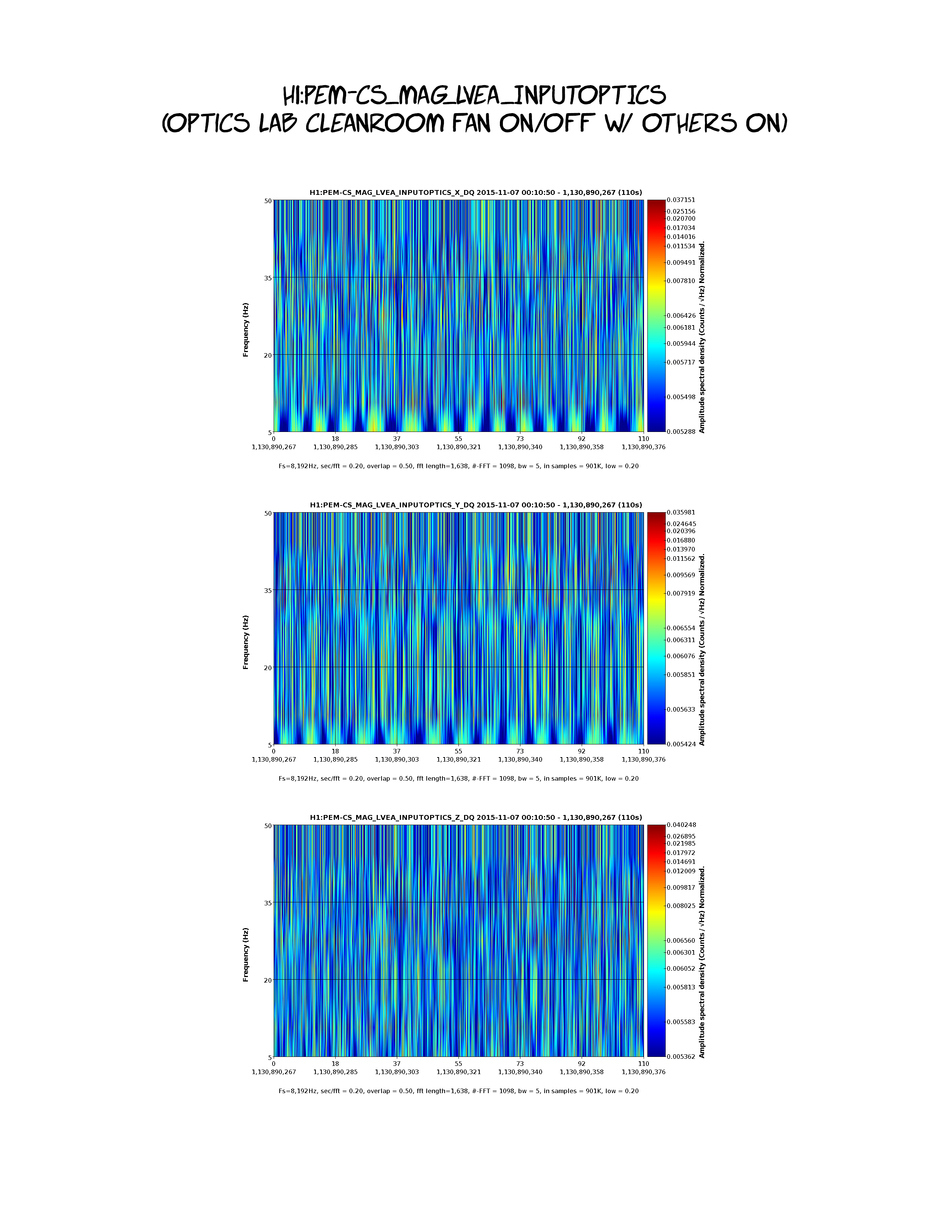
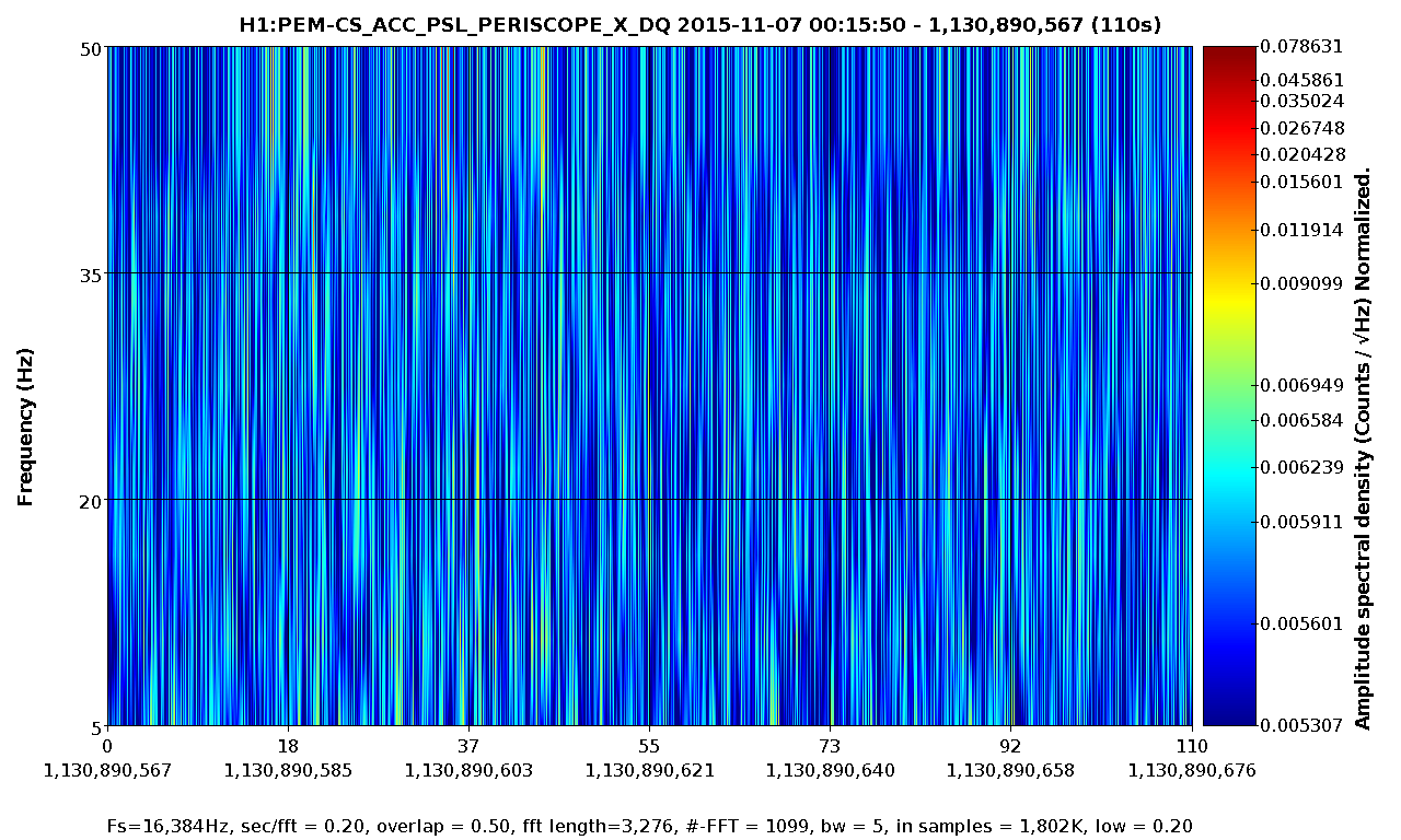
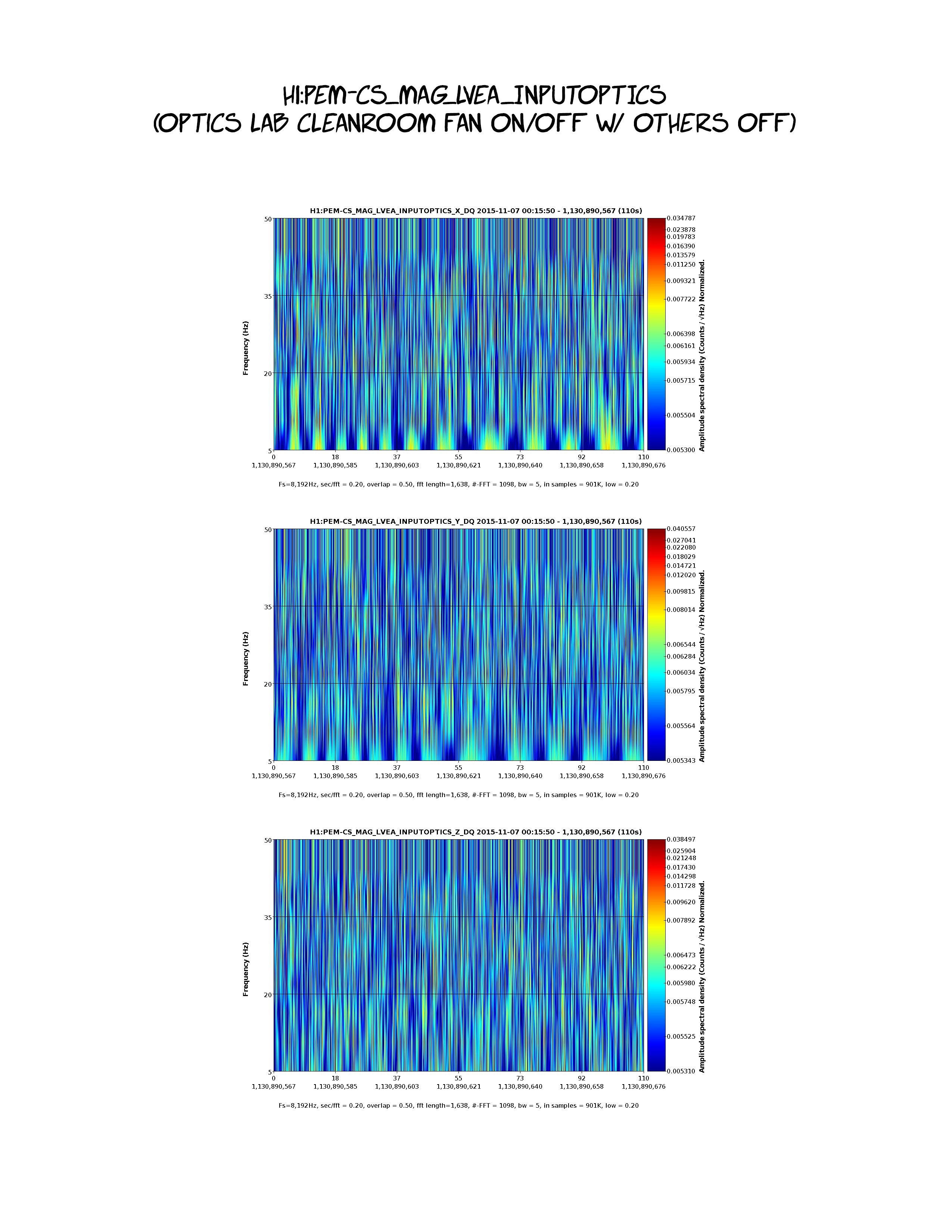
Displaying reports 65581-65600 of 83069.Go to page Start 3276 3277 3278 3279 3280 3281 3282 3283 3284 End
Reports until 17:33, Monday 20 April 2015
H1 CDS (CAL, IOO, ISC)
jeffrey.kissel@LIGO.ORG - posted 17:33, Monday 20 April 2015 (17962)
A few more SDF files updated in prep for RCG 2.9.1 Upgrade
I've updated the SDF files for the following models, who each had about ~10-20 channels discrepant with their previous set point.
h1alsex (Shiela / Elli / Evan speeding up the ALS acquisition)
h1alsey (Sheila / Elli / Evan speeding up the ALS acquisition)
h1calcs (Gamma Coefficient tuning by me)
h1ascimc (matrix tuning from Gabriele)
H1 General
thomas.shaffer@LIGO.ORG - posted 16:00, Monday 20 April 2015 (17960)
Ops Day Shift Summery

730 - Karen and Cris to LVEA

843 - Filiberto to Beer Garden to set up seismometer

916 - Filiberto back

929 - Kyle to LVEA to climb on HAM6

946 - Kyle back

1030 Gerardo taking a small group through the LVEA (cleared with Kiwamu)

H1 ISC
gabriele.vajente@LIGO.ORG - posted 15:17, Monday 20 April 2015 (17959)
Simulation of SRCL to DARM coupling

I simulated to coupling of SRCL displacement noise into DARM signal, for a full dual recycled interferometer with aLIGO like parameters. The longitudinal locking point is tuned by zeroing the simulated error signals, in the same way it's done in the real world.

In summary, the coupling of SRCL to DARM, in the ideal case, is a straight 1/f^2 line. However, it's easy to add an additional high frequency component, rising as f^2, by adding some defects:

So my guess is that at LLO the change in the TF is due to a SRCL longitudinal offset. The non stationarity of the noise at LHO can be explained both with angular motion of the ETMs and residual SRCL fluctuation.

Images attached to this report
H1 SUS
betsy.weaver@LIGO.ORG - posted 15:12, Monday 20 April 2015 - last comment - 16:21, Monday 20 April 2015(17958)
SUS SDF update effort continued

This time I set the SDF to ignore more OMC settings which have been tuned to switch over the last few weeks (BIO/COILs).  I also set more LOCK bank switches to be ignored which are in a guardian somewhere adn keep popping up.  More to come since there is an upgrade tomorrow...

All sus safe.snaps have been committed to SVN.

Comments related to this report
betsy.weaver@LIGO.ORG - 16:21, Monday 20 April 2015 (17961)

Wth Dan, I also cleared out OMC ASC channel diffs accumulated recently.

H1 CAL (CAL, DetChar, ISC)
jeffrey.kissel@LIGO.ORG - posted 12:57, Monday 20 April 2015 - last comment - 09:08, Friday 24 April 2015(17951)
Studies on the Precision of DARM Calibration
J. Kissel, K, Izumi

I had started the weekend hoping to improve the DARM calibration in the following ways:
(1) Including the compensation for the analog and digital anti-aliasing (AA) and anti-imaging (AI) filters.

(2) Decreasing the DARM coupled cavity pole by 25% to 290 [Hz].

(3) Establishing an uncertainty estimate of the optical gain (the DC scale factor component of the sensing function).

(4) Reducing the delay time in the actuation from four 16 [kHz] clock cycles to one 16 [kHz] clock cycles.

After study, and Sunday's improvement to the power recylcing gain, we've decided not to make *any changes to the calibration, yet. 
However, for the record, I put down what I've studied here, so we can begin to understand our uncertainty budget.

%% Details
-----------
(1) Including the compensation for the analog and digital anti-aliasing (AA) and anti-imaging (AI) filters
LLO has pioneered a method to compensate for the high frequency effects of the analog and digital (or IOP) AA and AI filters, by including the *product* of all four filters in the actuation chain of the front-end CAL-CS model (see the last few pages of G1500221 and LLO aLOG 16421). 

Further, Joe has analyzed a collection of 281 real, analog AA/AI filters that were tested during CDS acceptance testing to refine the exact frequency response of these filters (see first attachment, aLIGO_AAAI_FilterResponse_T1500165.pdf). In summary, the 3rd order Butterworth's corner frequency is statistically significantly lower; measured to be 8.941 (+0.654 /-0.389 or +7%/-3%) [kHz] instead of the ~10 [kHz] Butterworth model that we have been using (which was inherited from a .mat file the 40m). Though this does not appreciably affect the magnitude error at high-frequency, it does as much as 3 [deg] of phase by 2 [kHz], which can throws off our estimate of the residual unknown time delay by 5 [us] when we try to account for it in our fitting of the open loop gain transfer function.

However, after exploring what LLO has implemented, we've discovered a flaw in the implementation of this compensation. In going from the continuous zpk model of the filters to discrete, because we're trying to model these filters which have all of their response near, at, or above the Nyquist frequency, there is significant difference of modeled filter's response between the continuous and discrete models (see second attachment 2015-04-18_AAAI_FilterStudy.pdf). 

As such, we will *not* begin to compensate for the AA and AI filtering until we arrive at a better method for compensating these filters.

(2) Decreasing the DARM coupled cavity pole by 25% to 290 [Hz].
Over the past few weeks, we've established the DARM coupled cavity pole is now at 290 [Hz] instead of the predicted L1 value of 389 [Hz] (see LHo aLOG 17863). We've added one more DARM open loop gain transfer function to the list we're now comparing after the HAM6 vent,
Apr 13 2015 04:15:43 UTC % Post HAM6 Vent & UIM/TST Crossover; 10 [W] input power
Apr 13 2015 06:49:40 UTC % No loop parameter changes, but input power 15 [W]
Apr 15 2015 07:53:56 UTC % Input Power 15 [W] no change in control system from previous measurement 
with these three measurements, I made a statistical comparison of the model / measurement residual while using 290 [Hz] for the modeled coupled cavity pole frequency, and reducing the unknown time delay from 40 [us] to 30 [us] because I've used Joe's measured mean for the  analog AA / AI in the model (see third attachment 2015-04-18_290HzCCP_H1DARMOLGTF.pdf ). As one can see on the 3rd and 4th page, assuming each of the residuals frequency points is a measurement of the the true OLGTF value with a Gaussian distribution, the uncertainty in the frequency dependence of the OLGTF model is now a 1-sigma, 68% confidence interval of +/- 1.5% in magnitude and 1 [deg] between 15 and 700 [Hz] (IF we change the CCP frequency to 290 [Hz], compensate for the AA and AI filters, and include 30 [us] of unknown delay). Note that this assumption of Gaussianity appears to be roughly true for the magnitude, but not at all in phase (I'm still thinking on this). Also note the each one of these frequency points has passed a 0.99 coherence threshold on a 10 [avg] measurement (and most have coherence above 0.995), so the individual uncertainty for each point is sqrt((1-coh)/(2*nAvgs*coh)) = 1 to 2%.

Recall the frequency dependence of the model is determined by the following components included in the model:
- The 1/f^2 dependence of the [m/N] suspension transfer function (as modeled by the QUAD state space model)
- The 2000 [Hz] ESD driver pole
- The analog and digital anti-imaging filters
- The 130 [us] of actuation delay from 1 16 [kHz] cycle of SUS Computation, 3 65 [kHz] cycles of IOP Error Checking, 1 65 [kHz] cycle of IOP Computation, and 1/2 65 [kHz]  cycle for Zero-order Hold Delay
- The DARM filters
- The single-pole response (at 290 [Hz]) of the optical plant 
- The analog and digital anti-aliasing filters
- The 76 [us] of sensing delay from 1 65 [kHz] cycle of IOP Computation, 1 16 [kHz] cycle of OMC Computation
- The 30 [us] of unknown time delay

As a cross-check, I recalculated the comparison with the CCP frequency that's currently used in the model, 389 [Hz], and found that at around the high-frequency PCal lines, roughly ~535 [Hz] the model / measurement discrepancy is 25-30%. This is consistent with what the PCAL calibration reports at these frequencies, a DARM / PCAL (which is equivalent to model / measurement) discrepancy of 25-30% -- see LHO aLOG 17582. At the time, the PCAL team reports their internal uncertainty to be in the few-percent range.

This had convinced me on Saturday that I had enough information to "officially" change the DARM CCP frequency in the CAL-CS front end, but Gabriele and Evan have since changed the alignment scheme for the corner station to improve the power recycling cavity gain by improving the ITM DC alignment LHO aLOG 17946. This will have an effect on the signal recycling cavity and therefore the DARM CCP frequency, so we'll wait until we get a few more OLGTFs in this new configuration before changing anything.

(3) Establishing an uncertainty estimate of the optical gain (the DC scale factor component of the sensing function).
After refining the precision of the frequency dependence in magnitude, this allows to quantify the precision to which we can estimate the overall DC scale factor that one needs to scale the model to the measured OLGTF; a factor that we traditionally have attributed only to the change in optical gain between lock stretches. For this study, I've used *all* six DARM OLGTF TFs, see 2015-04-18_AllMeas_FittedCCP_H1DARMOLGTF.pdf. Note that this increases the uncertainty of the frequency dependence to a less Gaussian 2.5%, but as you'll see this is still plenty precise.

Recall that before transition to the OMC DCPDs, regardless of input power to the IFO, the OMC_READOUT sensor gain is changed to match the RF readout sensor gains which are already power normalized. That should mean that input power should have no affect on the measured optical gain, and this is a safe comparison. 

With 6 measurements, the mean scale factor for the OLG TFs is 1.05e6 +/- 26% [ct / ct]. This is consistent by the variation the DARM digital gain by 34% that was used for these 6 measurements. The current optical gain used for the sensing function the CAL-CS front end model is 1.1e6 [ct/m]. This 4% difference from the mean of the these 6 measurements is well within the 26% uncertainty, so we've concluded to *not* change anything there. 

All this being said, we have used the *same* actuation strength for all of these comparisons, but there is no guarantee that the actuation strength is not changing along with the optical gain.
- ETMY is controlled using the Test Mass (L3) and UIM (L1) stages
- The cross-over for these two stages in the two groups of measurements is ~1.2 [Hz] and 2.5 [Hz] (see 17713), and by 10 [Hz], the contribution of the UIM is roughly -25 [dB] and -15 [dB]. Therefore the ESD is the dominate actuator in the frequency region which we're we trying to 
- Static charge affects the actuation strength of the ESD by changing the effective bias voltage of the drive, as well as changing the amount of drive that's in the longitudinal direction (because the charge can migrate to different regions of the reaction mass / test mass gap), see e.g. G1500264, LLO aLOG 16611, or LLO aLOG 14853.
- If there is substantial residual charge on the ESD, the charge varies on the the ESD when Ion Pumps are valved into the chamber.
- It has been shown many times over that the charge varies on the few hour time scale when there is significant residual charge on the test mass and the ion pumps are valved in (see e.g., G1401033 or as recently as LLO aLOG 17772).
Thus, it is reasonable to suspect that the actuation strength is changing between these measurements. LHO has made no-where-near enough measurements (only a one-time comparison between ETMX and ETMY, see LHO aLOG 17528) to quantify how much this is changing, but here is what is possible:
- We have a physical model of the actuation strength (or at least more accurate equation for how the bias voltage determines the actuation strength, see above citations). I think we can take what we've seen for the variance (as high as +/- 400 [V] !!) and propagate that through to see how much of an affect it has on the strength
- PCAL lines at low-frequency (~30 [Hz]), compared against the DARM calibration lines should show how the optical gain is varying with time, it's just that no one has completed this study as of yet.
- Calculation of the gamma coefficient from the DARM lines should also reveal how the open loop gain transfer function is changing with time. In the past, we've assumed that changes in gamma are fluctuations in the optical gain because we've had actuators with non-fluctuating strength. 

Thus, for now, we'll incorrectly assign all of the uncertainty in the scale factor to optical gain, and call is 26%. Perhaps it will be much better to trust PCAL at this point and time, since it's precision is so much greater than this "scale the OLGTF model" method, but I would need a third measurement technique to confirm the accuracy. I think a power budget propagated to a shot noise estimate compared against the measured ASD (like in LHO aLOG 17082) is the easiest thing to do, since it can be done offline. Or we should resurrect the campaign to use the IMC VCO as a frequency reference, but this has the disadvantage of being an "offline, odd configuration" measurement, just like the free-swinging Michelson.

(4)Reducing the delay time in the actuation from four 16 [kHz] clock cycles to three 16 [kHz] clock cycles.
As mentioned above, the time delays that are included in this model are 
- The 130 [us] of actuation delay from 1 16 [kHz] cycle of SUS Computation, 3 65 [kHz] cycles of IOP Error Checking, 1 65 [kHz] cycle of IOP Computation, and 1/2 65 [kHz]  cycle for Zero-order Hold Delay
- The 76 [us] of sensing delay from 1 65 [kHz] cycle of IOP Computation, 1 16 [kHz] cycle of OMC Computation
- 30 [us] of unknown time delay (the equivalent of ~8-9 [deg] of phase at 700 [Hz])
for a total of 206 [us] of delay for which we've accounted, out of the total 236 [us] that's used to produce the above frequency-dependence comparison. So, there's a total of 3.4 or 3.9, 16 [kHz] cycles of known or known+unkuown time delay, respectively. Remember that the "L/c", light-travel time delay (13 [us]) is *less* than the one 16 [kHz] SUS clock cycle (61 [us]) delay that defines when the control signal arrives at the end station over RFM IPC, so we ignore it.

Since we only have the infrastructure add the delay in the actuation paths in CAL-CS, then we can only account for the *differential* delay between the two paths. If we assign the unknown delay to the actuation side of things, then the difference in delay between the two paths is (130+30)-76 = 84 [us] = 1.3 16 [kHz] clock cycles, leaving a residual overall delay of 76 [us]. If we assign it to the sensing function, we get 130-(76+39) = 24 [us] = 0.39 16 [kHz] clock cycles, leaving a residual of 130 [us]. Since we can't do less than 1 [kHz] clock cycle, we should chose to assign the unknown delay to the actuation function, apply one 16 [kHz] cycle delay to the actuation function, and suffer the 0.3 / 16384 = 18 [us] phase difference between the sensing and actuation path, and have to account for a 76 [us] delay in offline analysis.
Non-image files attached to this report
Comments related to this report
daniel.sigg@LIGO.ORG - 22:52, Monday 20 April 2015 (17965)

Your list of known delays doesn't seem to include the 13us (L/c) delay from the interferometer response (see e.g. eqn. 16 in T970101).

jeffrey.kissel@LIGO.ORG - 09:22, Wednesday 22 April 2015 (18002)
Daniel's right, details below. As such, the unknown time delay is 16 +/- 5 [us], 
For clarity I repeat the new list of time delays:
the time delays that are included in this model are 
- The 130 [us] of actuation delay from 
     - one 16 [kHz] cycle of SUS Computation, 
     - three 65 [kHz] cycles of IOP Error Checking, 
     - one 65 [kHz] cycle of IOP Computation, and 
     - one-half a 65 [kHz]  cycle for Zero-order Hold Delay
- The 89.3 [us] of sensing delay from 
     - one L/c delay sensing the ETM motion in the corner, 
     - one 65 [kHz] cycle of IOP Computation, and
     - one 16 [kHz] cycle of OMC Computation
- 16.7 [us] of unknown time delay (the equivalent of ~3-4 [deg] of phase at 700 [Hz])
for a total of 219.3 [us] of delay for which we've accounted, out of the total 236 [us] that's used in the model.

Details:
--------
More on the L/c time delay, as explained by Daniel:
I have said above,
"Remember that the "L/c", light-travel time delay (13 [us]) is *less* than the one 16 [kHz] SUS clock cycle (61 [us]) delay that defines when the control signal arrives at the end station over RFM IPC, so we ignore it."

Daniel agrees:
The fiber delay is n * L/c or about 20us. It doesn't matter because it is part of
the SUS cycle delay.

However, there is a sensing function delay. When you push the ETM (from the DARM actuation) it takes at least
L/c before you can measure a signal in the corner. This is a pure optical delay. This sensed control signal is indeed what we're measuring when we take an open loop gain transfer function.

For gravitational waves the situation is similar, the photons which travel forth and back in
the arm are, on average, sampling h(t) from half a round trip ago. In reality, this
is only exactly true for perpendicular incidence. 

As such, we should subtract 3994.465(+/- 7e-4) [m] / 299792458 [m/s] = 13.3 [us] from the "unknown" time delay, leaving us with a timing uncertainty of 16.7 [us]. Unclear yet what the uncertainty is in this number, since thus far it's merely fit by-eye to make the phase of the OLGTF residual flat. From playing around with the number in the fit, I would suggest a 5 [us] uncertainty on this unknown timing residual.

I'll update 
/ligo/svncommon/CalSVN/aligocalibration/trunk/Runs/PreER7/H1/Scripts/H1DARMmodel_preER7.m  
later today to reflect this knowledge.
koji.arai@LIGO.ORG - 10:18, Wednesday 22 April 2015 (18008)

OMC DCPDs have uncompensated poles at 13.7kHz and 17.8kHz due to their locations above the nyquist freq.
They cause the delay of ~18.5us. The details can be found in LHO ALOG 17647

jeffrey.kissel@LIGO.ORG - 08:12, Friday 24 April 2015 (18037)
I've confirmed Koji's statement with a bode plot, though I get a better "fit" with 20 [us] delay. But the point is moot.  I'll definitely just include this in the actual frequency response of the sensing function. This brings the unknown time delay to 0 +/- 5 [us] -- wow! Let's hope we don't find out about anything else. ;-) 

Also -- that means we should include this in the approximation for the super-Nyquist frequency response of the sensing function along with the digital and analog AA filters when we fix that it in the front-end.
Non-image files attached to this comment
jeffrey.kissel@LIGO.ORG - 09:08, Friday 24 April 2015 (18039)
I've reprocessed the results after adding the L/c arm delay and the OMC DCPD uncompensated high frequency poles mentioned above. Because we've replaced the equivalent unknown time delay with a known time delay of L/c 13.3 [us] and some very high-frequency poles, the results have actually changed very little and therefore the uncertainty in the frequency response of the OLGTF has changed very little: 
                                   Was                     Is Now
Magnitude Residual StDev:  1.0045 +/- 0.025318       1.0043  +/- 0.025309     
Phase Residual StDev:      0.4299 +/- 1.0307         0.23821 +/- 1.0534
However, there're less unknowns in the model, which is exactly what we want. 

As such, I stand by my earlier statement:

As one can see on the 3rd and 4th page, assuming each of the residuals frequency points is a measurement of the the true OLGTF value with a Gaussian distribution, the uncertainty in the frequency dependence of the OLGTF model is now a 1-sigma, 68% confidence interval of +/- 2.5% in magnitude and 1 [deg] between 15 and 700 [Hz] (IF we change the CCP frequency to 290 [Hz] -- which is now probably different, and find a good discrete approximation for compensating for the OMC DCPD poles, the AA, and the AI filters). Note that this assumption of Gaussianity appears to be roughly true for the magnitude, but not at all in phase (I'm *still* still thinking on this). Also note the each one of these frequency points has passed a 0.99 coherence threshold on a 10 [avg] measurement (and most have coherence above 0.995), so the individual uncertainty for each point is sqrt((1-coh)/(2*nAvgs*coh)) = 1 to 2%.


Details:
--------
I've added the following parameters to the params files:
par.C.omcdcpdpoles_Hz = [13.7e3 17.8e3]; % LHO aLOGs 18008 and 17647

par.C.armLength.x = 3994.4704; % [m] +/- 0.3e-3; LHO aLOG 9635
par.C.armLength.y = 3994.4692; % [m] +/- 0.7e-3; LHO aLOG 11611
par.C.speedoflight = 299792458; % [m/s]
and added the following lines to the DARM model
/ligo/svncommon/CalSVN/aligocalibration/trunk/Runs/PreER7/H1/Scripts/H1DARMmodel_preER7.m

par.C.uncompensatedomcdcpd.c = zpk([],-2*pi*par.C.omcdcpdpoles_Hz,prod(-2*pi*par.C.omcdcpdpoles_Hz));
par.C.uncompensatedomcdcpd.f = squeeze(freqresp(par.C.uncompensatedomcdcpd.c,2*pi*freq));

par.t.armDelay  = mean([par.C.armLength.x par.C.armLength.x]) ./ par.C.speedoflight;
Non-image files attached to this comment
LHO FMCS
john.worden@LIGO.ORG - posted 09:40, Monday 20 April 2015 (17954)
LVEA Temperature control

As it continues to warm we have turned off two stages of heat in the LVEA.

H1 PSL
thomas.shaffer@LIGO.ORG - posted 09:37, Monday 20 April 2015 (17953)
PSL Monday report

Laser Status:
SysStat is good
Front End power is 31.6W (should be around 30 W)
FRONTEND WATCH is RED
HPO WATCH is RED

PMC:
It has been locked 0 day, 17 hr 3 minutes (should be days/weeks)
Reflected power is 2.2 Watts  and PowerSum = 24.5 Watts.
(Reflected Power should be <= 10% of PowerSum)

FSS:
It has been locked for 0 h and 6 min (should be days/weeks)
TPD[V] = 1.27V (min 0.9V)

ISS:
The diffracted power is around 8.5% (should be 5-9%)
Last saturation event was 0 h and 6 minutes ago (should be days/weeks)
 

H1 SEI
filiberto.clara@LIGO.ORG - posted 09:19, Monday 20 April 2015 (17952)
STST-2 SN 88921 installed in Beer Garden PEM Area
PEM STS-2 S/N 88921 (from vault) was installed in beer garden, next to STS-2 ITMY-B. New seismometer will be connected tomorrow to help troubleshoot STS-2 ITMY-B. Unit was aligned along X-arm and leveled. Unit was left in unlock position.
H1 General
thomas.shaffer@LIGO.ORG - posted 08:42, Monday 20 April 2015 (17950)
Morning Meeting Minutes

SEI: Prep for tomorrow's RCG upgrade

SUS: Updating safe.snap and SDF

CDS: Setting up a seismometer in the beer garden

Vac: Briefly climbing on HAM6


Coming up:

Readiness test on May 1st and 2nd

ER7 on May 26 to June 2

H1 CDS (DAQ)
david.barker@LIGO.ORG - posted 08:27, Monday 20 April 2015 (17949)
CDS model and DAQ restart report, Saturday 11th - Sunday 19th April 2015

report attached.

Non-image files attached to this report
H1 ISC
evan.hall@LIGO.ORG - posted 23:41, Sunday 19 April 2015 (17946)
Recycling gain 40 W/W, ASC retuning

Gabriele, Evan

We spent some more time today on improving the interferometer recycling gain.

We started at 3 W with DARM controlled by AS45Q, and with the dETM, BS, cETM, and IM4 ASC loops engaged. We've switched the ordering back to an older configuration, so that cETM comes on before IM4 and PR2. This is intuitively appealing, since the motion of cETM appears in the IM4 and PR2 signals that we're using [REFL9IA − REFL9IB, and 0.5*(REFL9IA+REFL9IB)+0.83*(REFL45IA+REFL45IB), respectively], and therefore it is good to have it suppressed before these two loops engage.

Then by moving the ITMs (mostly ITMY; see attachment), Gabriele was able to bring the recyling gain from 32 W/W to 40 W/W. We had to move the SRM simultaneously to keep POP90 low.

At 40 W/W, the interferometer seemed pretty stable (and in fact lasted 90 minutes at this recycling gain), so we tried reengaging the rest of the ASC. We found that the PR2 loops had flipped sign, but otherwise engaged just fine. Then we tried engaging the ASC→SRM/SR2 loops after adjusting the QPD offsets. This seemed to work initially, but after about 60 seconds caused the interferometer to unlock.

After the lock loss, we relocked ALS (without touching the ITMs) and then updated the ITM camera spot positions. With a little more work, we can probably close the rest of the ASC tomorrow.

Images attached to this report
H1 ISC
gabriele.vajente@LIGO.ORG - posted 23:35, Sunday 19 April 2015 (17945)
MICH, SRCL and DARM boosts

Evan, Gabriele

Both the SRCL and MICH error signals showed a lot of low frequency residual motion. We implemented two boosts that give us a lot more gain at low frequency. We've been testing the SRCL boost few times in the last days and it always worked. Today we managed to engage the MICH boost a couple of times without problems. See the attached time series and spectrum comparisons.

The boosts are installed as FM1 in MICH and FM5 in SRCL. They are NOT autromated in the guardian.

Infected by the boost illness, we decided that DARM could have more too. Since we saw no good reason for the reduced low frequency gain, we modified the pre-existing boost, increasing the low frequency gain as shown in the third attachment.

Images attached to this report
H1 CDS
robert.schofield@LIGO.ORG - posted 17:10, Sunday 19 April 2015 (17944)
New I/O chassis power supply produces no non-60 Hz features, but I/O fans still show up

The power supplies in the I/O chassis are magnetically noisy and can couple to internal boards and the signal and power cables and connectors that are near the I/O chassis (here). CDS set up a test stand with a BNC AA chassis connected to an I/O box for testing a new type of power supply.  Figure 1 is a photograph of the setup with the old supply (box in the back corner) and new supply (card with the gloved magnetometer on it). I was able to switch back and forth between the supplies. Two of the channels passing through the I/O box were used, one to carry the magnetometer signal, and a blank channel that was terminated at the AA chassis input. Figure 2 shows the spectra of the magnetometer channel for each power supply (the magnetometer was moved back and forth to sit on the active supply), and the coherence between the magnetometer channel and the blank channel.  The magnetic field from the old supply can be orders of magnitude larger than that of the new supply over broad regions. The old supply also displays the drifting features of beating high frequency oscillators.  The new supply only showed coherence at harmonics of 60 Hz while the old one impressed several lines and a region of increased coherence onto the blank channel. When the new supply was used, the blank channel level was a little lower, and did not have the drifting features most likely produced by beating high frequency oscillators in the old power supply (Figure 3). 

The second problem with the I/O chassis is that the fans at the front produce peaks in the channels that pass through it by power supply ripple (here - the peaks go away when a separate supply is used for the fans). Figure 3 shows that these fan peaks are present with both the old and the new power supply. One possible configuration to test is to power the fans directly off of the power supply card instead of off of the main board.

Robert, Richard, Dave, Jim

Non-image files attached to this report
H1 DetChar (CDS, DetChar, PEM, PSL)
andrew.lundgren@LIGO.ORG - posted 02:12, Sunday 19 April 2015 - last comment - 10:05, Wednesday 22 April 2015(17941)
PSL accelerometer signal glitching once per second
One of the accelerometers on the PSL table (PEM-CS_ACC_PSL_TABLE2_Z) is glitching once per second. The other accelerometers don't seem to have this problem. We noticed this because it was messing up our hVeto results. I searched for where these started, and as far as I can tell it's Apr 14 2:30 UTC (that's 7 PM on Monday local, I think). The onset takes a few minutes.

The first plot is an Omega scan from a few hours ago, showing the glitching. The second is a spectrogram of the onset.

We are seeing something similar in some of the ISI GS13s (maybe only ones in the center building?). They also have a once per second glitch, though it's not clear if it's related. Detchar will track that down more, and I'll alog it separately.
Images attached to this report
Comments related to this report
robert.schofield@LIGO.ORG - 14:11, Sunday 19 April 2015 (17943)

I have seen large 1 Hz combs in many places at the CS that are due to the Hartman Wavefront Sensor running at 1 fps (the capture rate of 57 at end stations makes a comb of huge peaks in DARM). I think that Ellie is going to keep the HWS off most of the time until we figure out why.

andrew.lundgren@LIGO.ORG - 01:56, Monday 20 April 2015 (17948)
Do you mean a 1 Hz comb in the spectrum, or glitches every second? This is the latter. Do you have an example of what this looks like? Also, is there an easy way to tell when the HWS is on?
aidan.brooks@LIGO.ORG - 11:11, Monday 20 April 2015 (17956)

We're implementing a Guardian script for ETM HWS control which engages the HWS when we lock, takes a measurement during the initial transient, then turns it off after thirty minutes or so. We'll look into implementing this at the corner station too.

Longer term - we need to look into what we might be able to do to eliminate the camera noise.

aidan.brooks@LIGO.ORG - 11:26, Monday 20 April 2015 (17957)

The camera can be turned on and off from Beckhoff. The channels you're looking for are:

H1:TCS-ITMX_HWS_DALSACAMERASWITCH

H1:TCS-ITMY_HWS_DALSACAMERASWITCH

eleanor.king@LIGO.ORG - 10:05, Wednesday 22 April 2015 (18006)

There are two channels to look at which are:

H1:TCS-ETMX_HWS_RCXCLINKSWITCH

H1:TCS-ETMX_HWS_DALSACAMERASWITCH

H1 ISC
sheila.dwyer@LIGO.ORG - posted 00:59, Friday 17 April 2015 - last comment - 09:51, Monday 20 April 2015(17919)
OMC fringe wrapping measurements

Sheila, Koji, Robert, Evan, Alexa, Dan

We have made several measurements of backscattering from the OMC.  It seems like the reflectivity of the OMC is smaller by a factor of about 20 than what was seen at LLO, and it seems that backscatter from the OMC is probably not limiting our DARM spectrum.  

Two nights ago, we measured fringe wrapping by exciting the OMC suspension in the longitudnal direction, as well as by exciting OM1.  (related alogs 17910 17904 17882)  The attached plots show the DCPD RIM, with the DARM loop supression removed, with the excitations on.  

Tonight Jeff made a test of turning off the HAM6 sensor correction, as was done at LLO (third attachment) (LLO alogs 16814).  The spectrum is attached, but we do not see the dramatic fringe wrapping seen at LLO.  We would expect the impact to be smaller here than in LLO because our scattering amplitude is smaller and it is also likely that the microseism could have been smaller here.  

Today we Robert Koji and I made injections into all 6 DOFs on the OMC to see fringe wrapping.  We saw nothing by exciting roll or vertical, we were able to produce shelves by exciting L, T, P and Y.  The last screenshot attached shows the sectra with the various excitations on. For the record, here are times, all excitations were at 0.2 Hz, into the test filter banks.  While I've attached spectra of these, several off these shelves were moving around durring the measurement because of some lower frequency motion. 


DOF ampltide counts time April 16-17th UTC
L 20000 23:47-23:51
T 20000 23:59-0:05
V 20000 0:14-0:18
P 2000 0:24-0:29
Y 200 0:31-0:35
R 2000 0:39-0:42

Images attached to this report
Non-image files attached to this report
Comments related to this report
jeffrey.kissel@LIGO.ORG - 07:41, Friday 17 April 2015 (17924)
Thanks to Sheila for logging my scattering measurements, apologies for not putting it up myself. 

A few more relevant comments on it:
- The experiment involved turning off both the HAM6 *and* HAM5 sensor correction (independently). 
- HAM6 shows no affect but HAM5 caused lots of non-stationary noise, from which the captured HAM5 curve is only a representative bump/glitch/effect. 
- Just after I got that spectra, the IFO broke lock. This is why I didn't get an ASD of the GS13s/CPSs on the ISIs exposing the full region where sensor correction ON/OFF should have an impact (down to ~0.1 [Hz], since we're using the Hua, FIR sensor correction on all DOFs on all the HAMs).

My locking skills are still minimal, so I wasn't able to bring the IFO up past 1f DRMI (the ISC_LOCK message complain of to little light on AS90, I tried nudging the BS out of ignorance, and that re-broke the DRMI lock, and the next automation attempt failed during ALS acquisition and I gave up).
koji.arai@LIGO.ORG - 12:53, Friday 17 April 2015 (17932)

There was some question about the shotnoise RIN level in the ISC meeting. We have ~20mA total current on the OMC DCPDs.

This corresponds to the shotnoise of 4e-9/rtHz. It is consistent with these attached plots.

keita.kawabe@LIGO.ORG - 09:51, Monday 20 April 2015 (17955)

DCPD1 and DCPD2 are perfectly coherent around the shelves.

At Stefan's suggestion, here's the coherence between DCPD1 and DCPD2 around the injection shelves. The coherence is almost 1 for the first shelf. As for the second shelf the coherence is not as perfect but it is almost 1 at the highest peak of the scattering shelf, and the flat part of this shelf is already pretty close to the noise floor.

We're either looking at something that comes through the OMC (as opposed to large angle scattering reflected by some random thing and unfortunately falling on the DCPDs), which is more likely, or something that come from the opposite side of the BS for the DCPDs, which sounds unlikely.

Images attached to this comment
H1 ISC
evan.hall@LIGO.ORG - posted 05:00, Thursday 16 April 2015 - last comment - 06:12, Thursday 30 April 2015(17905)
FF performance: MICH ok, SRCL not good

Koji, Evan

Summary

MICH feedforward seems to be doing its job, although there is room for improvement by implementing a frequency-dependent subtraction.

SRCL coupling into DARM seems to be very nonstationary. Consequently, the feedforward is not working.

Details

We injected band-limited white noise (elliptic bandpass, 10 Hz to 1 kHz, 6 ct amplitude) first into MICH, then into SRCL, to test the feedforward that was implemented a few weeks ago.

For MICH, frequency-independent subtraction is fair to middling (red) compared to no subtraction (blue); at best we get 20 dB of subtraction around 150 Hz. Note that the TFs in this plot use the whitened DARM channel. The whitening is undone for the spectra in the fourth pad.

For SRCL, the 1/f2 feedforward via ITMY L2 gives no subtraction at all. The attachment shows the TF of SRCL control → DARM with the feedforward off and with broadband noise injected into the SRCL error point. Unlike MICH, appearance of this excitation in DARM is highly nonstationary, fluctuating by a factor of 2 or so in a frequency-dependent way. Additionally, the coherence is poor above 20 Hz, despite the excitation elevating the DARM noise by more than an order of magnitude from 20 to 100 Hz.

The shape of the excess noise is more or less the shape of the 100 Hz elliptic cutoff that we put into SRCL a few weeks ago. Is it possible that the SRCL control noise explains the nonstationary, 100 Hz "scattering" shelf that we've seen in the DARM spectrum this past week?

Images attached to this report
Comments related to this report
evan.hall@LIGO.ORG - 07:59, Thursday 16 April 2015 (17907)

Using the measurements described above, here is a projection of MICH and SRCL control into DARM. It seems that these two noise sources, along with DAC→ESD noise, can explain most of the DARM noise from 10 to 70 Hz. There is still some excess from 80 to 200 Hz, and an overall excess in the high-frequency noise floor.

For MICH, I used the coherent transfer function we measured earlier. For SRCL, I estimated the TF magnitude by dividing the ASDs of DARM and SRCL (after subtracting off their quiescent values). The dtt files are in evan.hall/Public/2015/04/FullIFO/Noise as MichNoise.xml and SrclNoise.xml.

Some times (all UTC):

  • Quiet data: 07:55:00 to 08:02:00
  • MICH excitation: 08:12:22 to 08:14:22 with MICH FF off, 08:08:58 to 08:10:58 with MICH FF on
  • SRCL excitation: 09:22:10 to 09:25:10 with MICH FF and SRCL FF on, 09:26:05 to 09:28:05 with MICH FF on and SRCL FF off, and 09:28:15 to 09:30:15, no FF.

After these measurements, I also tuned the PRCL→SRCL subtraction in the LSC input matrix from 0.005 to -0.04 (using in-vac POP). This reduced the appearance of a 122 Hz PRCL excitation in the SRCL error signal by 20 dB.

Non-image files attached to this comment
evan.hall@LIGO.ORG - 22:32, Sunday 19 April 2015 (17947)

For completeness, here is the same budget as above, with intensity and frequency noises included.

We suspect that the sharp shelf at 100 Hz in the frequency noise projection might be coupling via SRCL, rather than directly to DARM. So between the frequency and SRCL projections, there may be some double-counting of noise in DARM.

Frequency, intensity, and DCPD dark noise are not enough to explain the excess noise between 200 Hz and 4 kHz. It seems they can somewhat explain the uptick in noise above 4 kHz.

Non-image files attached to this comment
evan.hall@LIGO.ORG - 06:12, Thursday 30 April 2015 (18126)

Slightly updated/corrected version attached.

Non-image files attached to this comment
Displaying reports 65581-65600 of 83069.Go to page Start 3276 3277 3278 3279 3280 3281 3282 3283 3284 End