I have turned off the violin mode damping filters for IX and IY by zeroing their gains. Patrick accepted these into SDF so that we can go to observing.
This is meant to be temporary, i.e., for this one lock only.
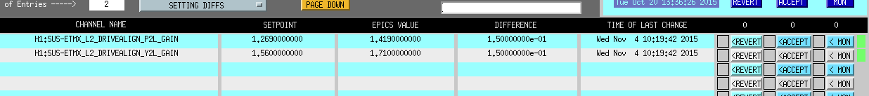
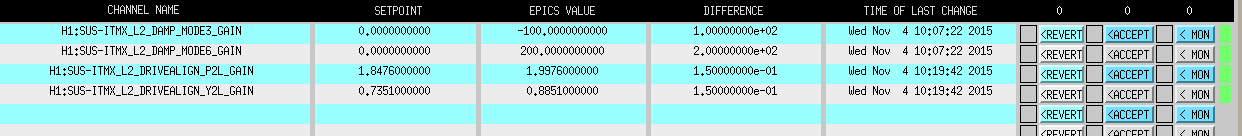
The next time the interferometer comes into lock, the Guardian will turn on the normal violin mode damping settings. These settings will appear as SDF diffs (two on IX, and six on IY). These should be accepted into SDF.
We do not expect these modes to ring up during the course of the lock. However, if the mode height on the control room DARM spectrum around 500 Hz rises above 10−16 m/rtHz, the damping should be turned back on:
-
Make sure the ramp times for the damping filter modules are at least a few seconds (currently they seem to be set to 10 s).
-
The filters should already be configured to provide the right damping phase, so changing the filters should not be necessary.
-
Start typing in gain settings. Refer to the values listed below. If the violin mode amplitude is much much higher than usual (e.g., it's off the scale on the control room DARM spectrum), it is wise to start with a small gain (e.g, gain of ±1) in order to make sure the suspension drive does not saturate. Then you can increase the gain in several steps, until the nominal setting is achieved.
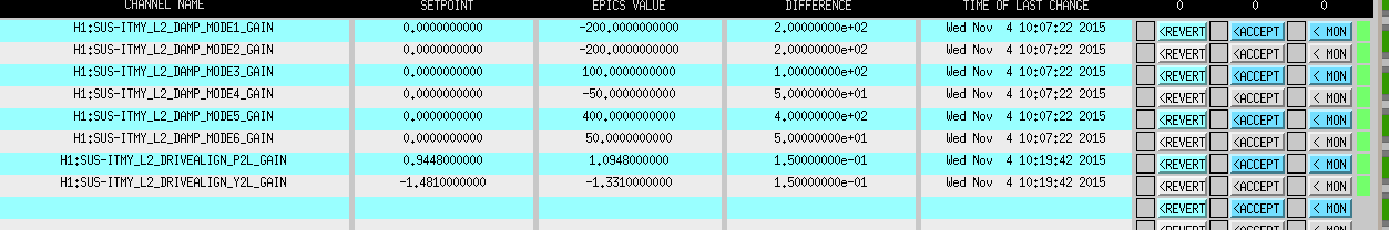
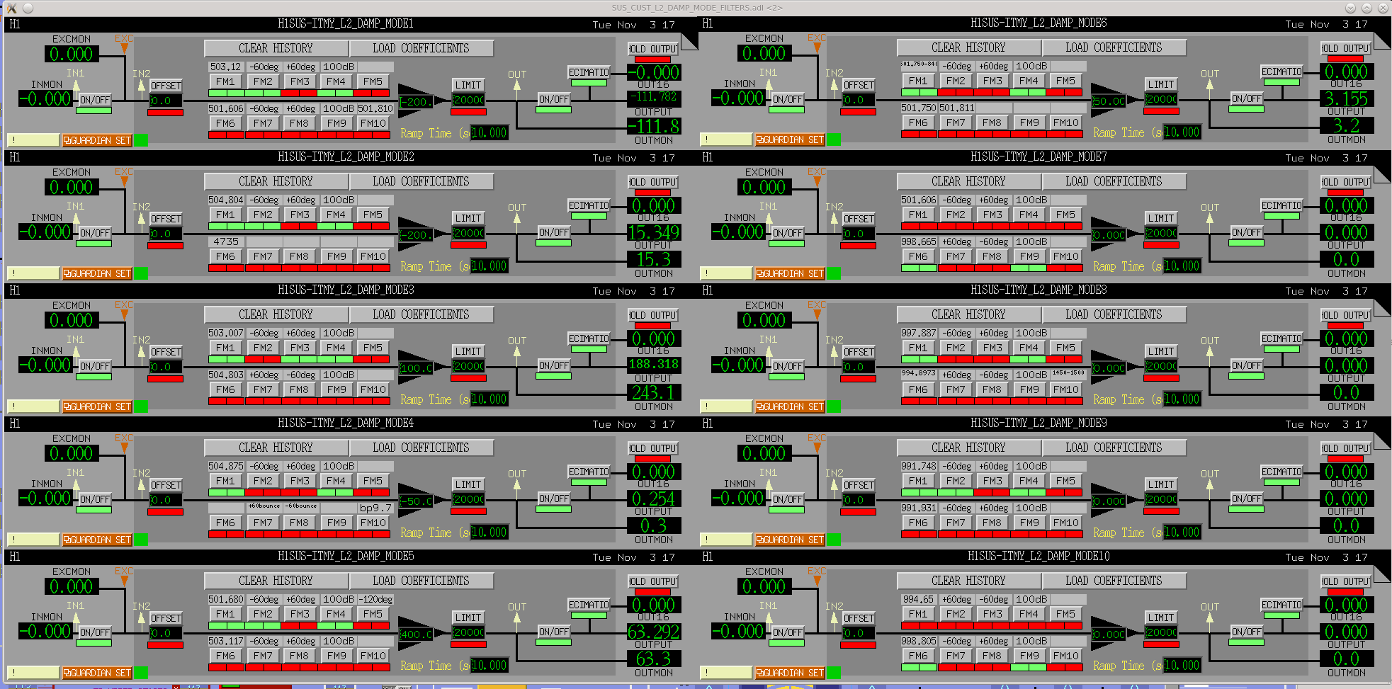
A screenshot of the nominal IY damping settings is attached (I didn't take one for IX).
ITMX:
-
MODE3 gain: −100
-
MODE6 gain: +200
-
all others zero
ITMY
-
MODE1 gain: −200
-
MODE2 gain: −200
-
MODE3 gain: +100
-
MODE4 gain: −50
-
MODE5 gain: +400
-
MODE6 gain: +50
-
all others zero


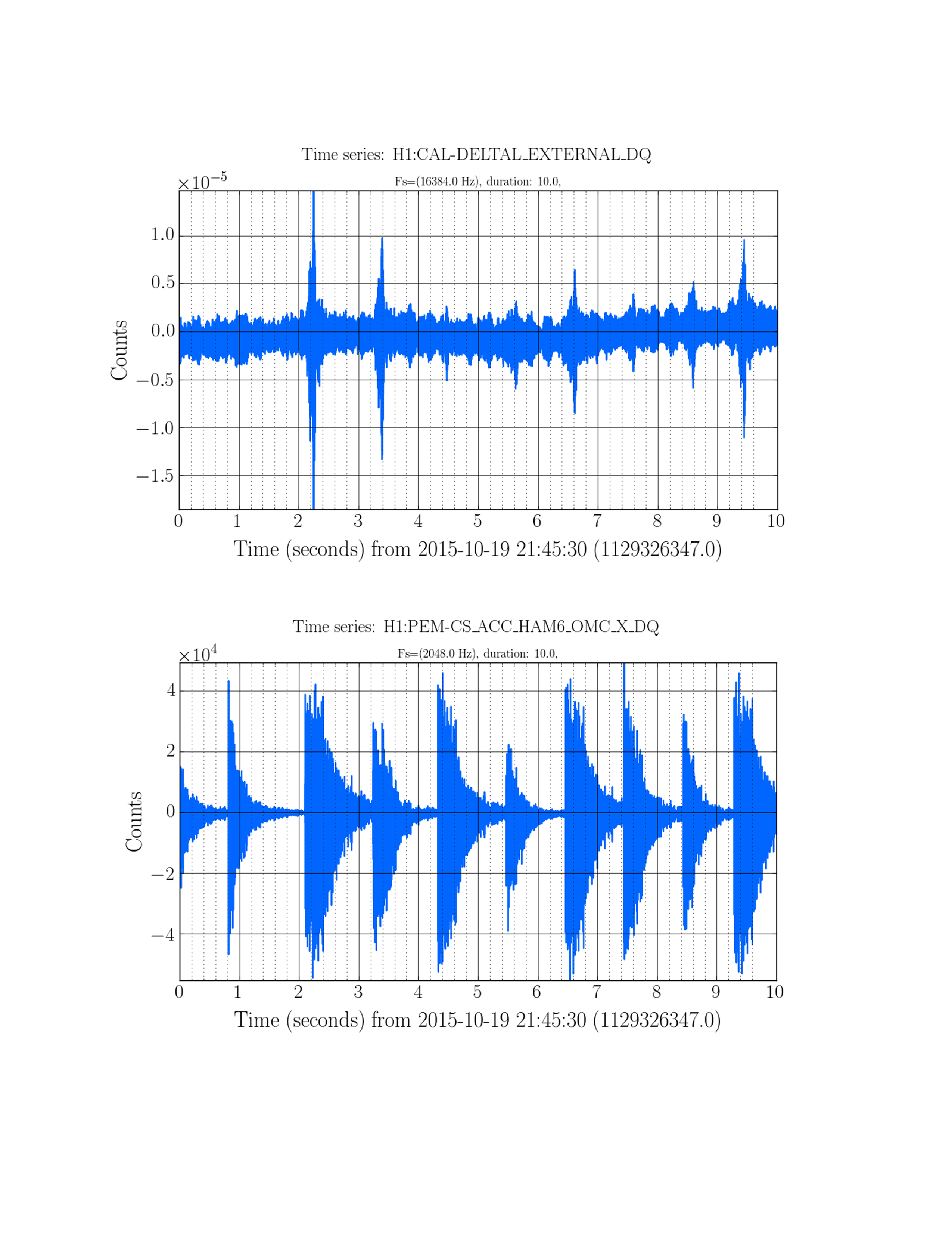

Fil and I went to the ISC rack and started tapping the 45 MHz cable that comes out of the patch panel. As noted before, this cable is extremely microphonic. Tapping on the coiled-up portion produces huge burps in the EOM driver control signal.
We added some extra velcro around the coil, and then fixed the coil to the rack with some zip ties.
However, now that we have relocked it seems that this does not improve the situation.