Title: 10/31 Eve Shift 23:00-7:00 UTC (16:00-24:00 PST). All times in UTC.
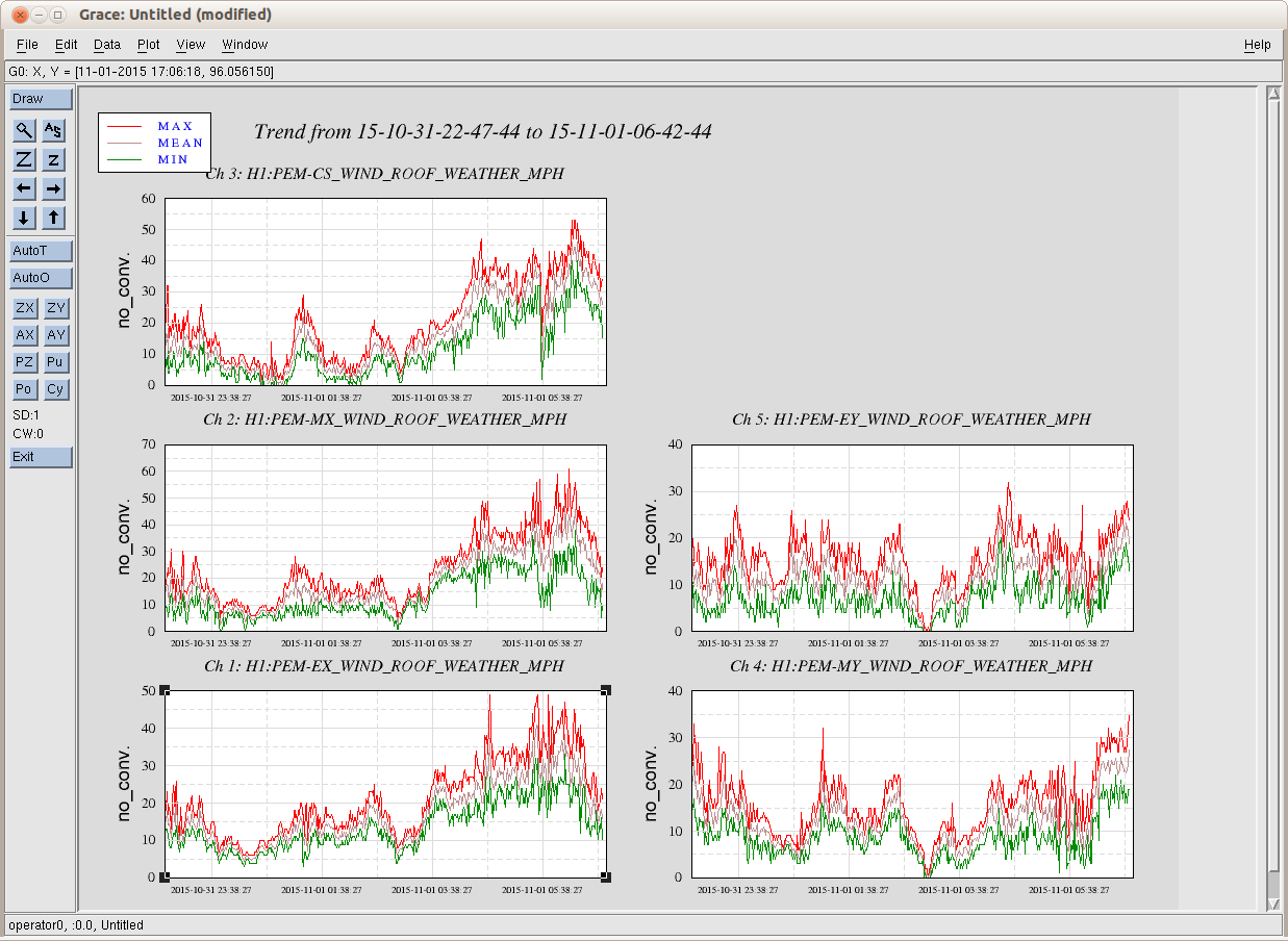
State of H1: Unlocked due to wind
Shift Summary: Wind calmed briefly, and after Hugh's TFs finished, I attempted locking. Got as far as locking DRMI once before winds kicked back up to 40-60mph. Called Mike to discuss whether TJ should bother to come in for his shift. He advised to tell TJ to monitor the wind remotely and come in once they have began to calm. Microseism is also ~0.6 um/s.
Incoming operator: TJ (monitoring environmental conditions from home)
Activity log:
2:49 In prep for locking attempt, adjusted Ref. signal to -1.94V to bring diffracted power to ~8.5%
3:01 HAM 1 HEPI restored after Hugh's TFs finished
3:12 began initial alignment
4:25 gave up on locking after struggling to get to DRMI and wind continue to increase