jeffrey.kissel@LIGO.ORG - posted 19:41, Friday 30 October 2015 (22991)
Charge Measurement Update: New Oplev Measurements align better with PCAL Line Estimates after Bias Flip
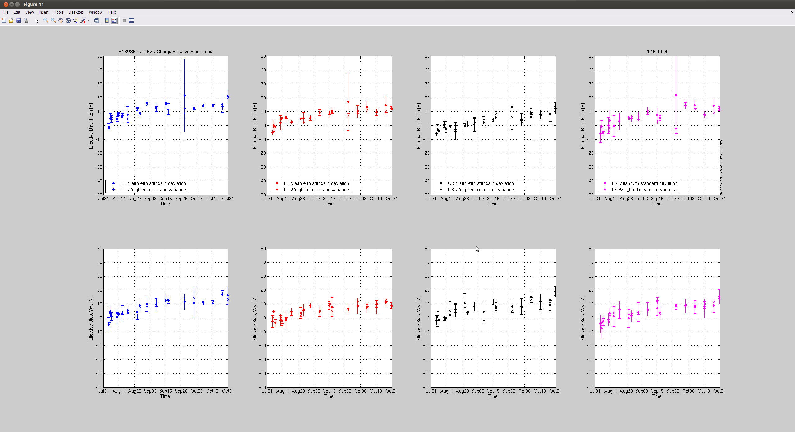
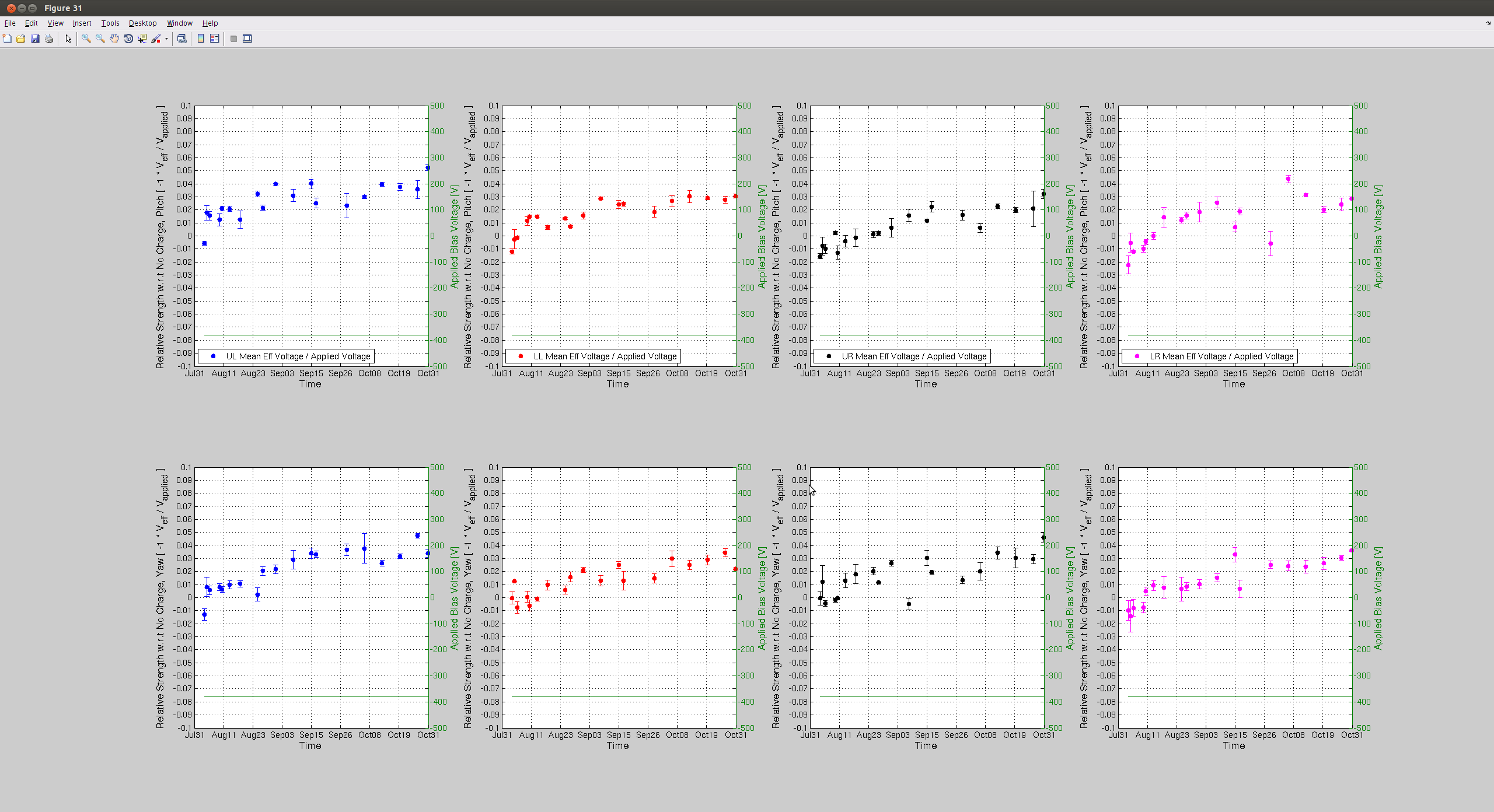
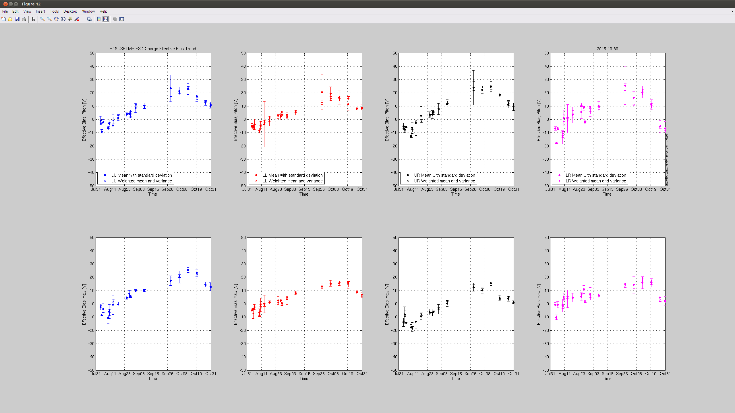
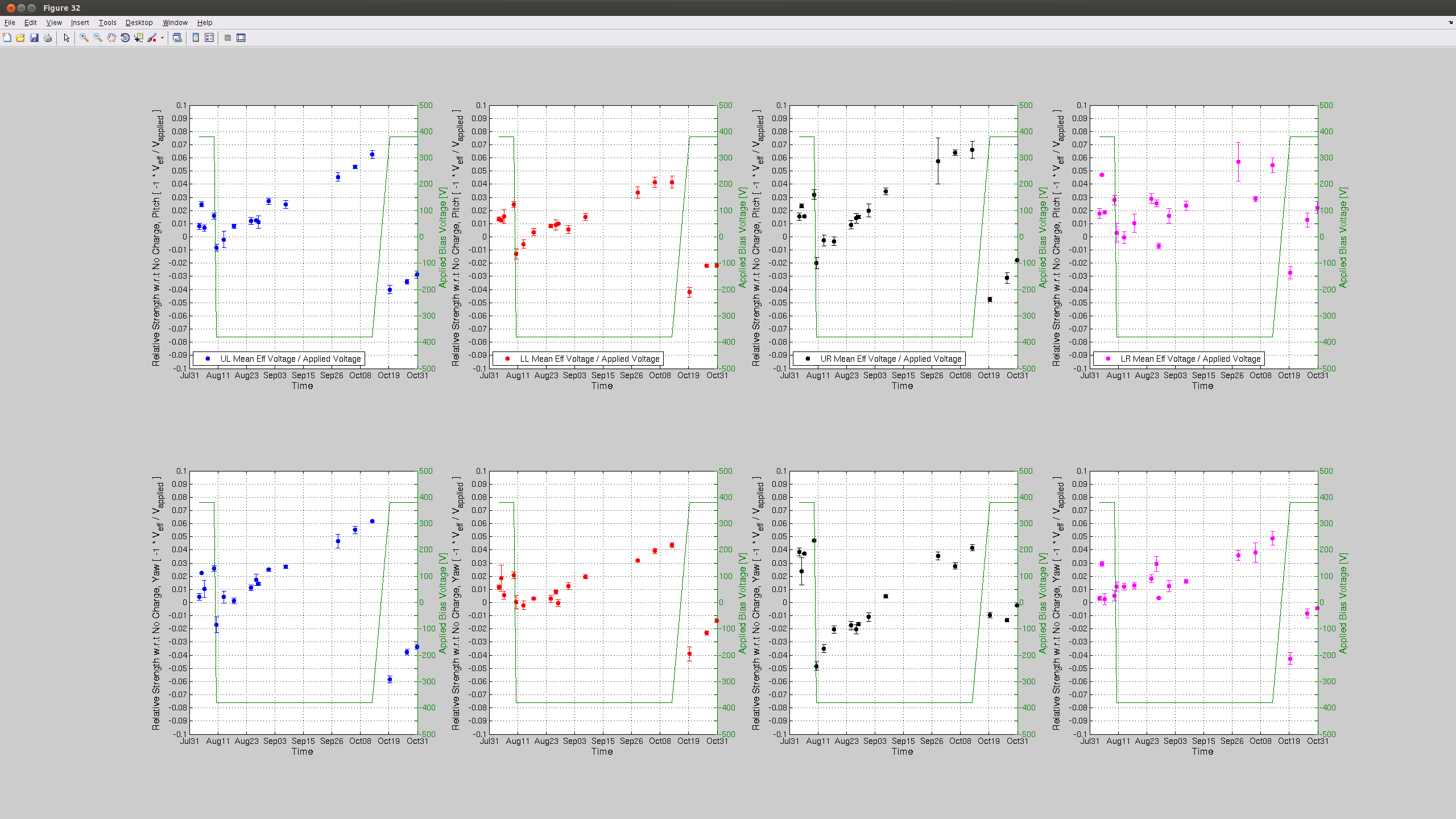
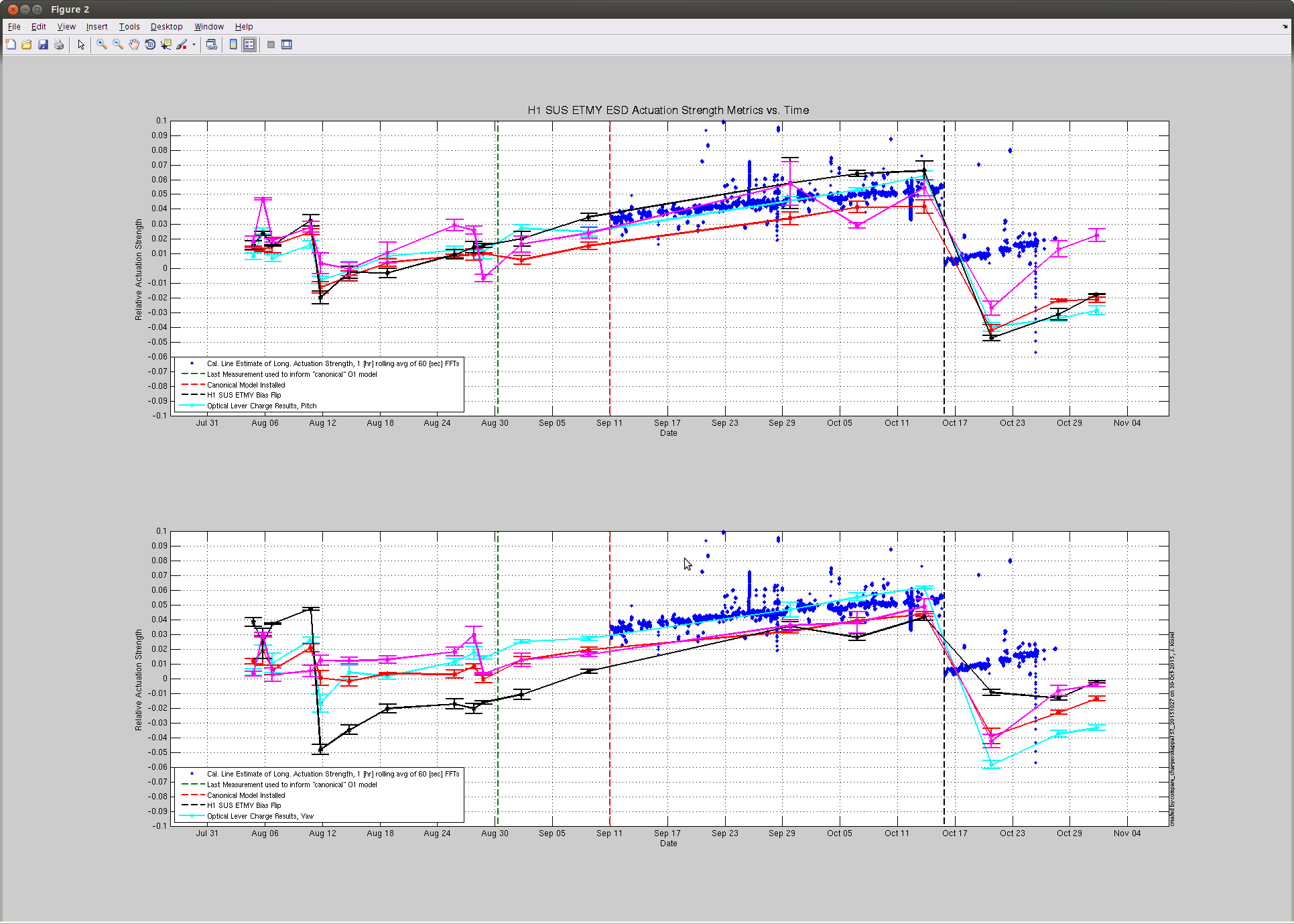
J. Kissel

Taking advantage of the windy down time, I grabbed another set of optical lever charge measurements this evening on both the ETMs. Two bits of news:
(1) The results from Tuesday had shown good agreement between optical lever vs. photon calibrator (cal lines, or kappa_TST) estimations of the H1 SUS ETMY ESD actuation strength, until the recent ETMY bias flip. However, with today's points, we can see that the first measurement after the flip was an outlier and the latests two match the slope much better. All is well, it just re-re-reminds us that it's difficult at best to claim a trend from only one or two optical lever charge measurements, you need several measurements over the course of days to establish a reliable trend.
(2) The H1 SUS ETMX effective bias voltage or charge continues to remain stagnant. Unlike prior to the start of the run, where the rate of increase (or decrease) in charge would stay constant after a bias sign flip, ETMX broke the mold by leveling off after teh start of the run. Recall that we've had a pretty good low-noise duty cycle, which means that the ETMX ESD Bias has been turned OFF for 70-80% of the past few months. This is great evidence to show how turning off or reducing the bias on the ESD attacts less charge. It's also good evidence to support the theory that it is indeed the high ESD bias voltage that is attracting whatever free charged particles are left in the chamber -- as opposed to the alternative mechanism of slow drift in the electric potential of the cage.

Apologies, I don't have updates to the kappa_TST coefficient, but given its consistency, I don't expect that it's slope has changed at all, and youu can just draw a mental line through the past ~week's trend.
Images attached to this report
Non-image files attached to this report