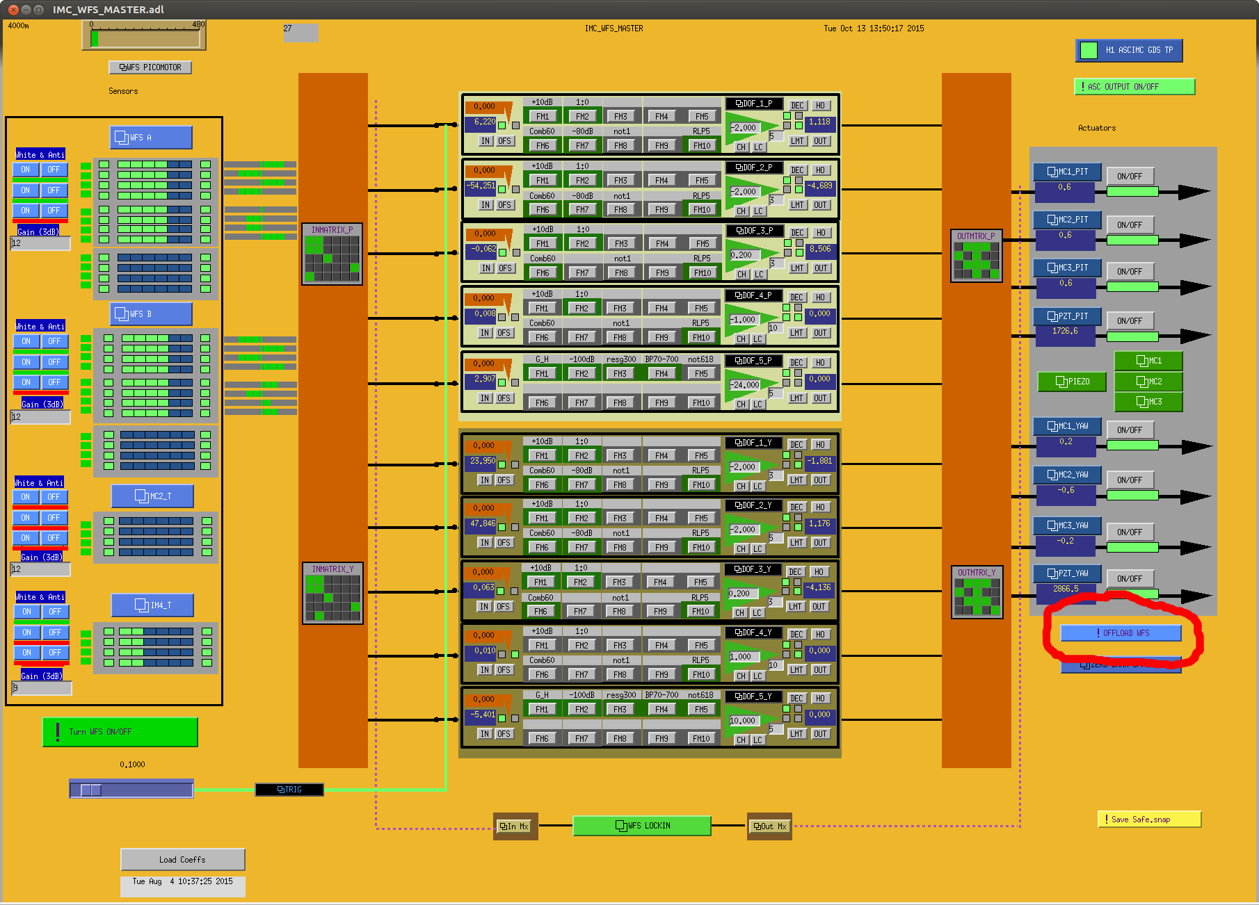
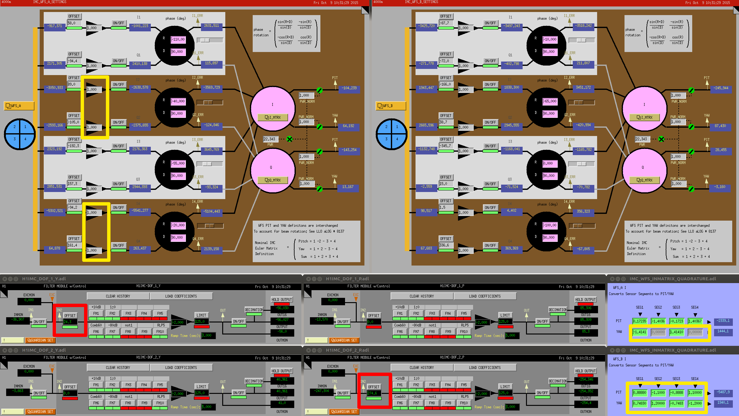
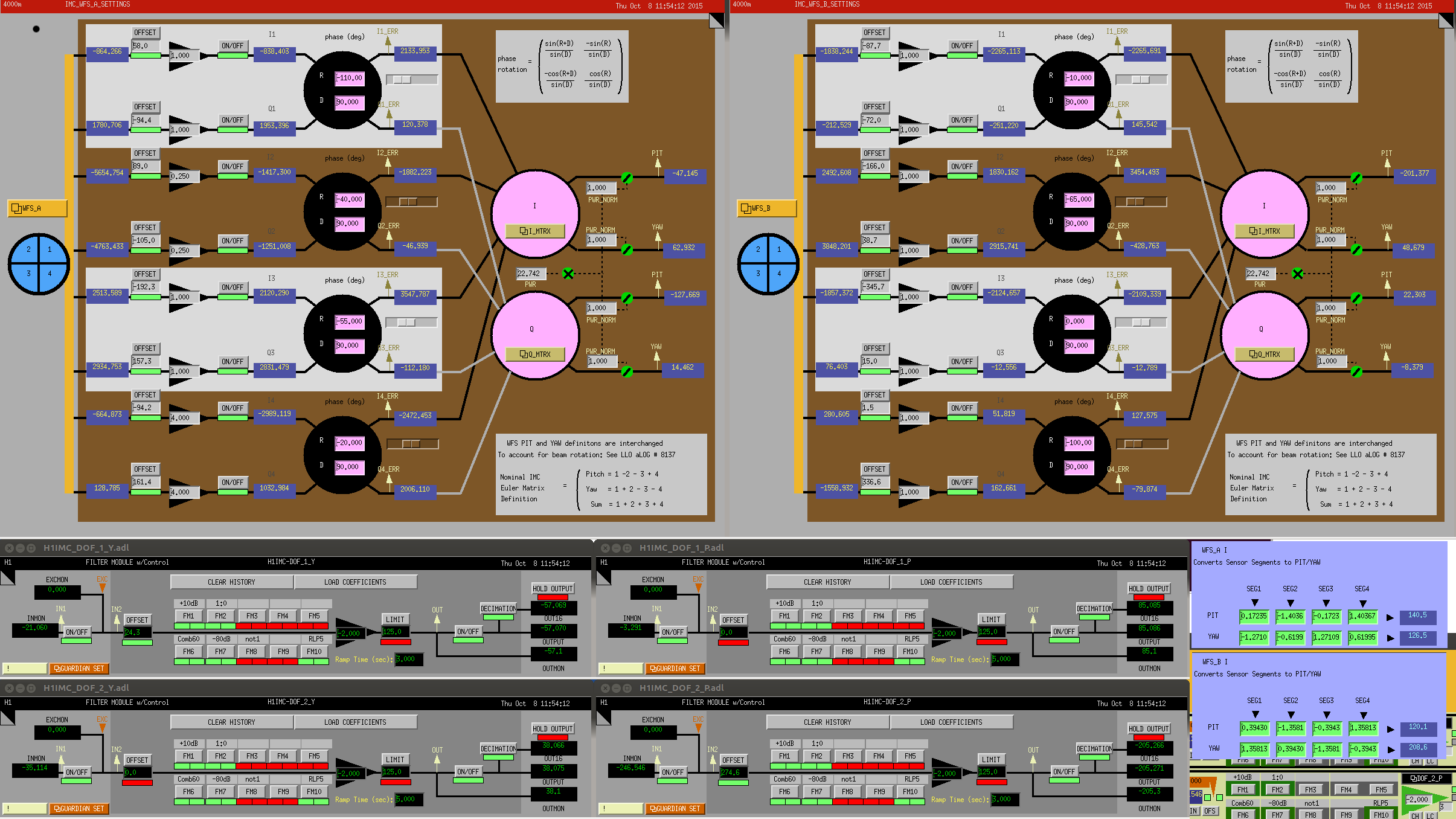
I have disabled the IMC WFS offsets that Keita and Cheryl wanted to remove (alog 22370).
This may help the recent ISS issue (alog 22449) somewhat, but probably not a lot.
Background
I was investigating why the ISS recently started having the trouble in engaging the 2nd loop. A first thing I noticed is relatively high RIN after the IMC. It seems that the IMC adds some extra RIN below 1 Hz as the light goes through it. A large RIN at low frequencies can easily hinder the PID control of the 2nd loop when engaging. So this seemed suspicious to me.
Since the ISS 2nd loop had been running without a significant issue in the past, perhaps until the recent change on the IMC WFS (alog 22362), I speculated that the current IMC alignment is at a non-optimal point where the low frequency RIN became worse. One factor which affects the IMC alignment is the WFS offsets that are meant to minimize the jitter-to-RIN couplings. In the end, I decided to get rid of the offsets because it gave a better RIN coupling.
IMC_LOCK guardian edited
To disable the offset, I have commented out lines 555 and 556 in the IMC_LOCK guardian. They are now,
#ezca.switch('IMC-DOF_2_P', 'OFFSET', 'ON')
#ezca.switch('IMC-DOF_1_Y', 'OFFSET', 'ON')
RIN is better without the offsets
I did a simple test where I measured RIN after the IMC with and without the WFS offsets. Note that the offsets have been applied only on DOF2_P and DOF1_Y. They have not yet been optimized after the change in the IMC WFS. The measured RIN are shown in the attached screenshot.
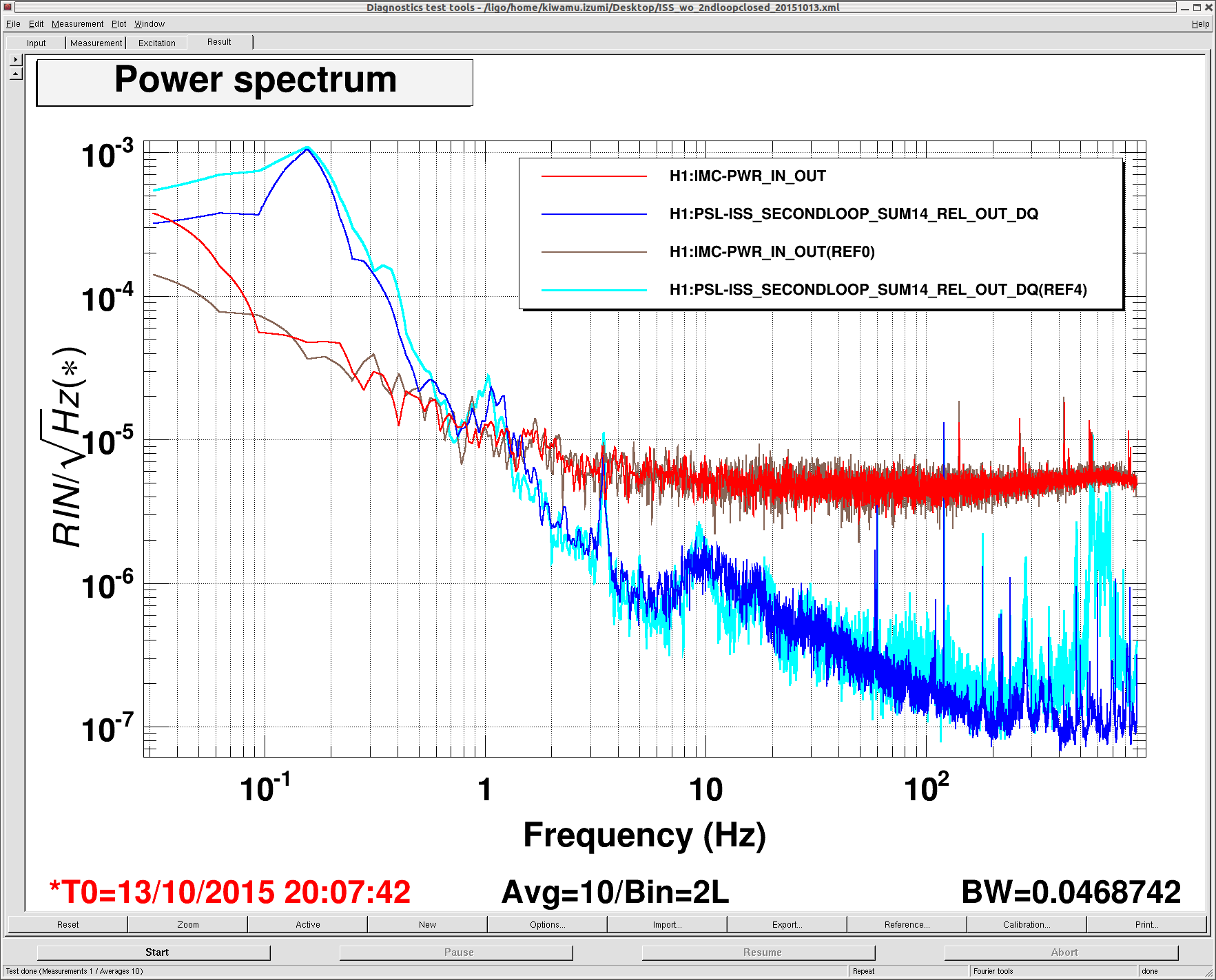
Blue: RIN at the ISS in-vac array without the offsets, Cyan: RIN at the ISS in-vac array with the offsets, Brown and red: RIN before the IMC with and without the offsets, respectively. The 1st loop was always ON while the 2nd loop was always OFF. The input power was about 2 W.
First of all, it is clear that RIN after the IMC is higher than that before the IMC by a factor of more than 10 at around 0.1 Hz. I am not sure how long it has been like this.
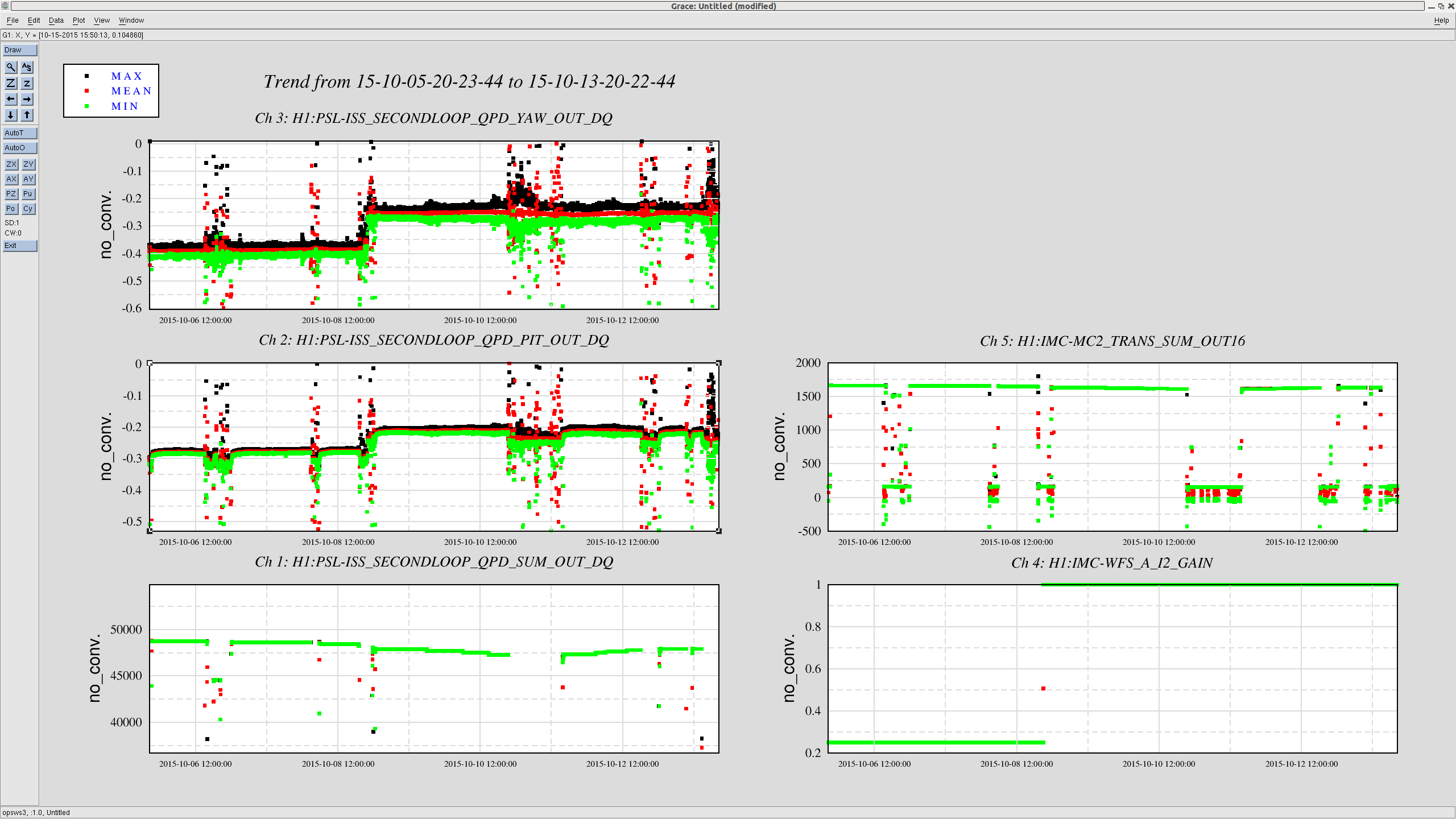
Next, as shown in the plot, removing the offsets reduced the excess RIN below 1 Hz somewhat at the in-vac ISS array. This was repeatable and therefore I think the improvement is real. Additionally, it got rid of a nasty structure at around 600 Hz. Also, some peaks above 100 Hz decreased their peak heights by a factor of few. These improvements were consistenly observed at IMC-MC2_TRANS_SUM as well. Therefore I think they are real improvement in RIN and not some kind of spurious couplings such as spatial jitter.
So overall, the configuration without the offsets seems better in terms of RIN. Perhaps this is an indication of better WFS sensing. I decided to disable the offsets in the IMC_LOCK guardian. I did not try to optimize the offsets yet. So this can be a next action item.