thomas.shaffer@LIGO.ORG - posted 11:18, Saturday 10 October 2015 (22391)
Back to Observing
Back to Observing at ~73Mpc after Robert's work, LLO is still down.
Back to Observing at ~73Mpc after Robert's work, LLO is still down.
While LLO is down, Robert will do some injections
Title: 10/10 DAY Shift: 15:00-23:00UTC (8:00-16:00PDT), all times posted in UTC
State of H1: Observation Mode at 74Mpc
Outgoing Operator: Travis
Quick Summary: No issues, it was locked his whole shift with a handful of saturations as usual. Microseisms are VERY high, wind is between 5-20mph, and LLO is currently down.
Title: 10/10 Owl Shift 7:00-15:00 UTC (0:00-8:00 PST). All times in UTC.
State of H1: Observing
Shift Summary: Locked for the entire shift in Observing. Wind and seismic calm. A typical number of ETMy saturations.
Incoming operator: TJ
Activity log:
14:45 Landscapers on site
Locked in Observing Mode for the past 12 hours.
Activity Log: All Times in UTC (PT)

23:00 (16:00) Take over from Ed
23:00 (16:99) Intent Bit set at Observing
23:40 (16:40) Finished GRB hold
23:58 (16:58) Kyle & Gerardo – Back from Mid-Y
06:15 (23:15) Nutsinee – Left the site
07:00 (00:00) Turn over to Travis


End of Shift Summary:

Title: 10/09/2015, Evening Shift 23:00 – 07:00 (16:00 – 00:00) All times in UTC (PT)

Support: Marissa

Incoming Operator: Travis

Shift Summary:
- 23:00 (16:00) IFO locked. Intent Bit set to Commissioning. Wind is moderate, some seismic activity.
- 23:00 (16:00) Received GRB alert at 22:40 – Held site in stand down mode until 23:40 (16:40).

    A smooth and quiet shift. Some wind (gust up to mid 30mph) and moderate seismic activity in first part of shift. Wind and seismic activity settling down toward end of shift. Had nine (9) saturation alarms during shift.
   IFO has been locked at NOMINAL_LOW_NOISE, 22.4w, 76Mpc, in Observing mode for first four hours of the shift. The wind is moderate (between 5 & 20mph), microseism is steady at <0.5micron/s. Higher frequency seismic activity has been declining all shift.
   In a GRB hold from 22:40 (15:40) to 23:40 (16:40.)
   There have been six (6) ETM-Y saturation events thus far this shift. All other IFO vital signs are normal.
Kyle, Gerardo

1140 hrs. local -> Spun up LD, Turbo and QDP80

1330 hrs. local -> 7.1 x 10⁻⁸ torr*L/sec with cal-leak open -> closed cal-leak -> < 10-11 torr*L/sec with cal-leak closed -> Calibration is OK

1335 hrs. local -> Valved-in Turbo to Y-mid volume -> Y-mid background initially found to be 1.8 x 10⁻⁸ torr*L/sec -> Fell steadily to 8 x 10⁻⁹ torr*L/sec over the next 60 minutes of pumping

Begin Testing

1435 hrs. local -> Began leak testing aLIGO GNB spool welds -> "Bagged" flange-to-spool welds in 180 degree sections -> Applied 5 LPM helium flow at bottom of bag and pumped at top of bag via O2 sensor/pump -> Started 100 second timer when 0% < O2 < 7% -> No response for either flange (4 bagged sections) -> Tested butt welds of cylinder spool roll -> Bagged butt weld in three sections (from flange to stiffener, between stiffeners and from stiffener to other flange) -> Background remained steady at 8 x 10⁻⁹ torr*L/sec during entire test period until a few seconds before the conclusion of the last weld test at which point it began to climb -> Stopped helium flow -> signal continued to climb -> removed bags from two most recent welds tested -> signal continued to rise -> Signal peaked at 1.2 x 10⁻⁷ torr*L/sec (tens of minutes after stoppage of helium flow) -> Isolated LD from Turbo exhaust -> signal immediately fell to < 10-11 torr*L/sec -> Recombined LD to Turbo exhaust -> Opened up building exterior doors to air out room.

1645 hrs. local -> Valved-out turbo from Y-mid volume and shut down LD and pumps with Y-mid background at 4.6 x 10⁻⁸ torr*L/sec.

Conclusion:  In retrospect, we should have reduced the helium flow rate once a minimum O2% was achieved.  As is, we put more helium into the room that was necessary (calculate a total of 85 liters over 90 minutes).  As such, we cannot conclude that the last weld tested was the source of the signal response.  We did demonstrate, however, that there is a leak(s) at the Y-mid (as opposed to other explanations) when we isolated the LD from the Turbo exhaust and the signal immediately fell off.

I propose that for the next session we pump the Y-mid with the turbo for a few hours to get the background back into the 10-9 range then revisit the last two butt welds tested.
C. Cahillane

I have finally decided to check if linearly adding A_pu for uncertainty is okay.  It turns out it's conservative, and we get lower uncertainty bars if we propagate correctly.
The equation for A_pu is:
A_pu = A_pum + A_uim

We had been propagating uncertainty linearly like this:
σ_|A_pu| = |A_pum| * σ_|A_pum| + |A_uim| * σ_|A_uim|
σ_φ_A_pu = σ_φ_A_pum + σ_φ_A_uim

This is bad.
The correct way to propagate it is quadratically.  I do not yet have a nice write-up of my equations, but they will be included in DCC T1400586 hopefully soon.  There is no mysterious method of uncertainty propagation used, just simple first order Taylor expansion.
The plot below is my comparison of the correct vs. linear uncertainty propagation.
Plot 1 is the comparison including systematic errors in uncertainty.  Plot 2 is statistical uncertainty only.
Title:  10/09/2015, Evening Shift 23:00 – 07:00 (16:00 – 00:00) All times in UTC (PT)

State of H1: At 23:00 (16:00) Locked at NOMINAL_LOW_NOISE, 22.4W, 65Mpc

Outgoing Operator: Ed

Quick Summary: Wind is up around 15 to 20mph, seismic activity is up. At the shift change, we were under a GRB hold. Intent Bit is set to Observing.
Finished 1 hour GRB hold. During the hold we had three (3) ETM-Y saturation (1 at 23:09 (16:09)& 2 at 23:23 (16:23)).
TITLE: Oct 9 DAY Shift 15:00-23:00UTC (08:00-04:00 PDT), all times posted in UTC
STATE Of H1: Observing
LOCK DURATION:
SUPPORT: Mike L., Sheila, Robert
INCOMING OPERATOR: Jeff B.
Activity log:
18:24 Kyle and Gerardo are going out to MY to turn on pumps they’re using for leak checking. This activity was cleared with Mike L. They are to aLog the pump start time as accurately as they can.
18:40 Pumps at MY turned on
18:50 Kyle and Gerardo back to Corner station
20:14 Kyle and Gerardo driving back out to MY
21:00 Joe B called on TS to let us know that Livingston would be coming out of Scence mode fo commissioning work
21:05 Mike Landry called to give the green light on any testing anyone would like to do as Livingston has dropped out of Science Mode
21:14 Richard out to the roof to assist Robert in PEM work
21:30 Richard leaving the roof
21:43 IFO in to commissioning mode
21:42 Robert and Mitchell outside to do PEM injections
22:30 IFO back to Observing
22:39 Loud thump from Fil closing up the CR floor.
22:40 GAMMA RAY BURST alarm
Shift Summary: Landry gave the green light for Richard to connect antenna cables on the roof while in observing mode. Came out of Science mode to do some PEM testing while LLO was out doing some commissioning . Went back into Science mode coincidentally with Livingston at 22:30UTC. Winds had increased to near 40mph for a short while and are now back down to around 15mph. Microseism increased to .5 microns while EQ seismic holds at 2.3 microns. IFO locked at 4.6 Mpc. Gamma Ray burst @ 22:40UTC has us in “Standown” mode for the next hour.
22:30UTC
On Tuesday, while most of the IFO was down for various maintenance tasks, I grabbed a bunch of SUS spectra and started a Template directory.
I set all of the references to be the ~quiet, unlocked data from the down period of the IFO. These spectra could be run when trying to troubleshoot locking. On Tuesday, I was only able to collect the following, located in /ligo/home/ops/Templates/SUS_Spectra/
BS_NOISEMON_spectra.xml
BS_OSEMINF_spectra.xml
PR2_NOISEMON_spectra.xml
PR2_OSEMINF_spectra.xml
PRM_NOISEMON_spectra.xml
PRM_OSEMINF_spectra.xm
SR3_NOISEMON_spectra.xml
SR3_OSEMINF_spectra.xml
SR2_NOISEMON_spectra.xml
SR2_OSEMINF_spectra.xml
SRM_NOISEMON_spectra.xml
SRM_OSEMINF_spectra.xml
ITMX_NOISEMON_spectra.xml
ITMX_OSEMINF_spectra.xml
ITMY_NOISEMON_spectra.xml
ITMY_OSEMINF_spectra.xml
NOTE - Many of the lower stage NOISEMON channels look... weird. They should be used as a before/.after snapshot for troubleshooting only. Work to improve what the various strangenesses of these channels is on a few low priority to-do lists.
There are templates ready to collect the balance of the SUS spectra data, namely ETMs, MCs, PR3. We should do this when the IFO is set to DOWN for whatever reason. The spectra are quick to run, then update all references (currently bogus data) and resave.
While we were unlocked due to wind during my Sunday Owl shift, I managed to get through taking, updating, and resaving templates for:
ETMX_NOISEMON_spectra.xml
ETMX_OSEMINF_spectra.xml
ETMY_NOISEMON_spectra.xml
ETMY_OSEMINF_spectra.xml
PR3_NOISEMON_spectra.xml
PR3_OSEMINF_spectra.xml
21:44UTC
This was ok'd by Mike Landry. He's assisting Robert Schofield with PEM work.
FYI, I have suspended reporting of HWInjReport runs until I can fix the bug that is causing the anomalous absence of RAW and RDS injections. Once I have that fixed, I will perform a comprehensive run of HWInjReport starting from September 12, 2015 00:00:00 UTC.
Apologies for not giving notice sooner.
We remain in Science mode locked at 72Mpc. Activities are being filtered through Mike Landry via telephone. Kyle and Gerardo have gone to Mid Y to start vacuum pumps for leak hunting. Wind has increased to ≤25mph. Earthquake graph up to .23microns/s. Terramon reported an R-Wave velocity of .25µm from a 5.1 nea New Zealand and then a 5.2 near Chile. This is most likely the reason for the rise. Microseism is up to about .5microns/s. 2.5 hours - glitch free.
HAM4 and HAM5 have had strong glitches for the past several weeks (sorry if I missed this being reported already, I didn't turn it up in a search, we found these by accident). They are sometimes completely not there, but sometimes happening as fast as twice per second! Attached are a slew of plots taken roughly every two days for H1:ISI-HAM4_BLND_GS13RZ_IN1_DQ (but I also see the same in H1:ISI-HAM5_BLND_GS13RZ_IN1_DQ).
We don't have a good lead on these, but wanted to report. They look an awful lot like what we have seen before when the HWS camera was on, see e.g., 18531. I noticed a note in the log on August 25 "15:54 Elli – Going to Hartman table at HAM4", and I also noticed that the glitches started showing up after a long hiaitus around August 27th. However, if I have my sign correct (0=off) for the camera switch channels, then the HWS cameras in the central station are currently off in O1 running.
Assuming it's not HWS, we should probably check ISI actuators for DAC glitches or overflows.
I can confirm that the corner station HWS cameras are all turned off. So 0=off is correct. And If I'm reading the spectrograms correctly the glitch rate seems to change from day to day. HWS camera doesn't do that.
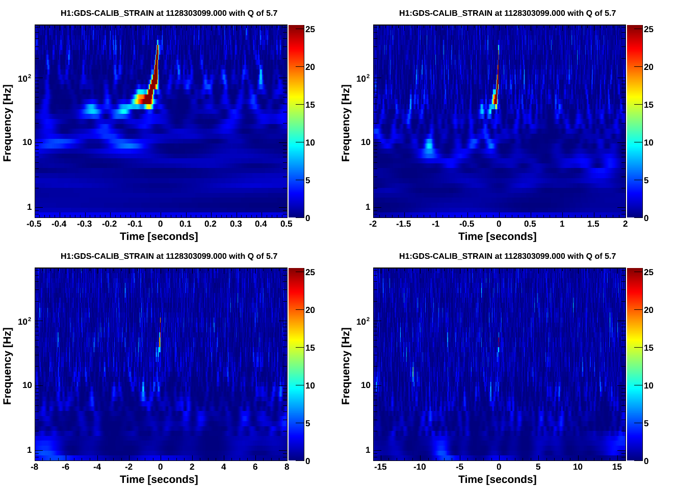
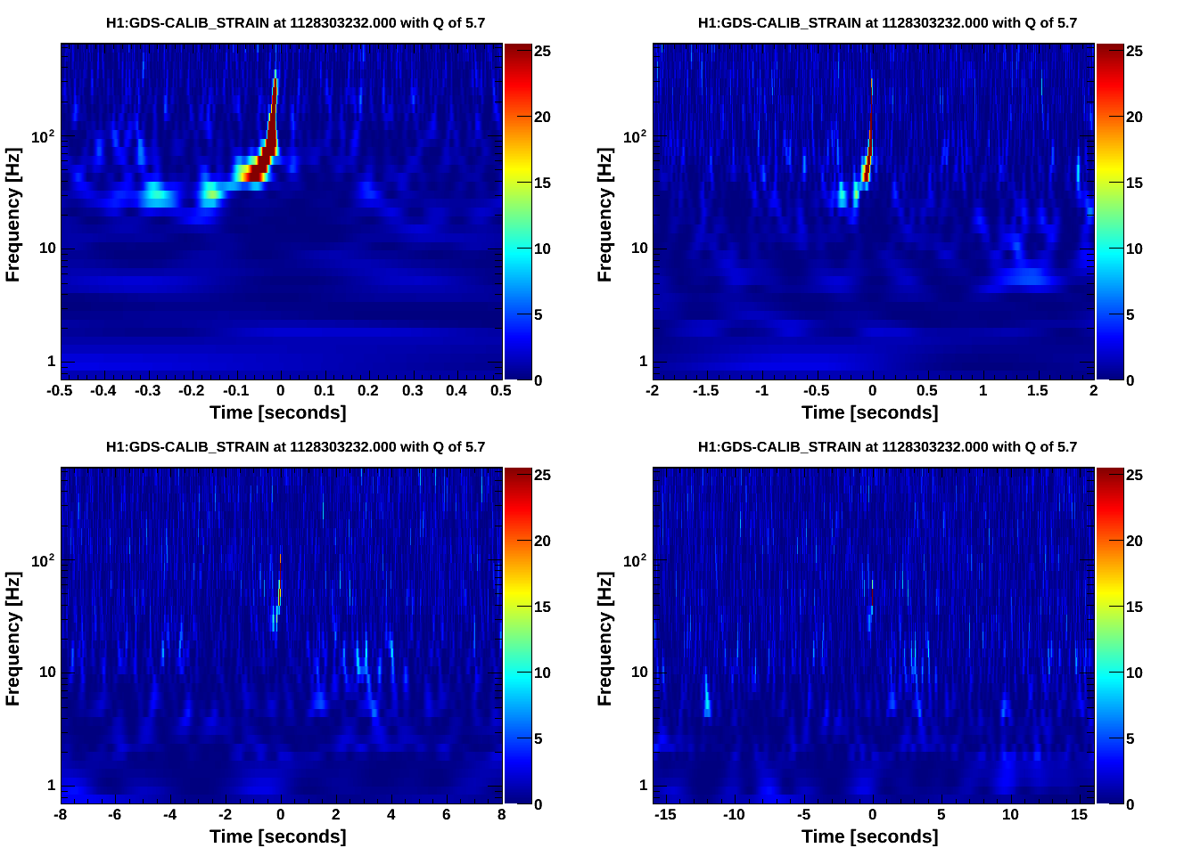
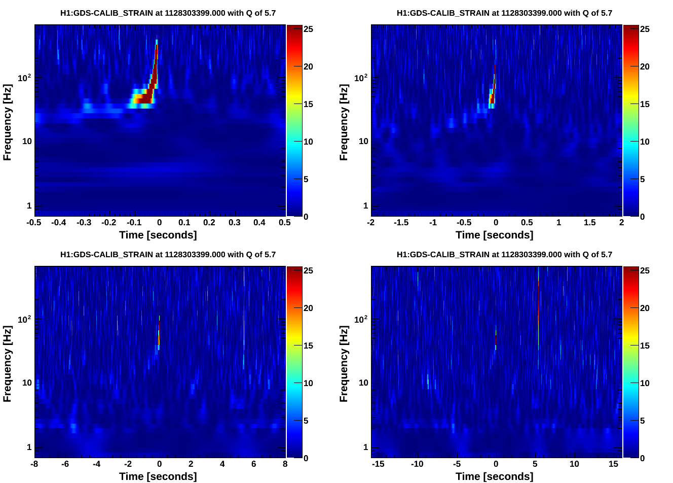
Summary:

We had single-IFO time so I tested the new inverse actuation filter for PCALX. WP5530

Sudarshan and I believe we tracked down the factor of 2 and sign error from the initial PCALX test, see aLog 22160. We wanted to do this test to confirm that.

CBC injections:

The waveform file is: https://daqsvn.ligo-la.caltech.edu/svn/injection/hwinj/Details/Inspiral/H1/coherenttest1from15hz_1126257408.out

The XML parameter file is: https://daqsvn.ligo-la.caltech.edu/svn/injection/hwinj/Details/Inspiral/h1l1coherenttest1from15hz_1126257408.xml.gz

I did three CBC injections. The start times of the injections were: 1128303091.000000000, 1128303224.000000000, and 1128303391.000000000.

The command line to do the injections is:
ezcawrite H1:CAL-INJ_TINJ_TYPE 1
awgstream H1:CAL-PCALX_SWEPT_SINE_EXC 16384 coherenttest1from15hz_1126257408.out 1.0 -d -d >> 20151006_log_pcal.out
awgstream H1:CAL-PCALX_SWEPT_SINE_EXC 16384 coherenttest1from15hz_1126257408.out 1.0 -d -d >> 20151006_log_pcal.out
awgstream H1:CAL-PCALX_SWEPT_SINE_EXC 16384 coherenttest1from15hz_1126257408.out 1.0 -d -d >> 20151006_log_pcal.out

I have attached the log. I had to change the file extension to be posted to the aLog.

DetChar injection:

I injected Jordan's waveform file: https://daqsvn.ligo-la.caltech.edu/svn/injection/hwinj/Details/detchar/detchar_03Oct2015_PCAL.txt

The start time of the injection is: 1128303531.000000000

The command line to do the injections is:
awgstream H1:CAL-PCALX_SWEPT_SINE_EXC 16384 detchar_03Oct2015_PCAL.txt 1.0 -d -d >> 20151006_log_pcal_detchar.out

I have attached the log. I had to change the file extension to be posted to the aLog.
Chris Buchanan and Thomas Abbott,
Quick follow-up with omega scans. It looks like most of the power is seen in GDS-CALIB_STRAIN about eight seconds after each listed injection time, consistently for each of these three injections. Doesn't look like there are omicron triggers for these times yet, but omega scans for GDS-CALIB_STRAIN are attached.
Full omega scans generated here:
https://ldas-jobs.ligo.caltech.edu/~christopher.buchanan/Omega/Oct07_PCALX_Inj1/
https://ldas-jobs.ligo.caltech.edu/~christopher.buchanan/Omega/Oct07_PCALX_Inj2/
https://ldas-jobs.ligo.caltech.edu/~christopher.buchanan/Omega/Oct07_PCALX_Inj3/
For complete documentation of the detchar safety injections:
The injections are 12 sine-gaussians, evenly spaced from 30hz to 430hz, 3 seconds apart with a Q of 6. There are three sets with increasing SNR of 25, 50, 100 (intended). However, the SNR is limited by the PCAL acuation range at higher frequencies.
To generate the waveforms I used the script written by Peter Shawhan / Andy located here: https://daqsvn.ligo-la.caltech.edu/websvn/filedetails.php?repname=injection&path=%2Fhwinj%2FDetails%2Fdetchar%2FGenerateSGSequencePCAL.m
I tuned the injections to stay within the PCAL actuation limits referenced in Peter Fritschel's document https://dcc.ligo.org/LIGO-
The intended time (seconds from start time of injections), freqency, snr, and amplitude (in units of strain) for all injections are pasted below:
__time__ __freq__ __SNR__ __AMP__
0.50 30.0 25.0 5.14e-21
3.50 38.2 25.0 4.96e-21
6.50 48.7 25.0 2.15e-21
9.50 62.0 25.0 2.07e-21
12.50 79.0 25.0 1.75e-21
15.50 100.6 25.0 1.78e-21
18.50 128.2 25.0 1.92e-21
21.50 163.3 25.0 2.06e-21
24.50 208.0 25.0 2.39e-21
27.50 265.0 10.0 1.11e-21
30.50 337.6 5.0 8.39e-22
33.50 430.0 5.0 8.51e-22
36.50 30.0 50.0 1.03e-20
39.50 38.2 50.0 9.92e-21
42.50 48.7 50.0 4.31e-21
45.50 62.0 50.0 4.14e-21
48.50 79.0 50.0 3.51e-21
51.50 100.6 50.0 3.55e-21
54.50 128.2 50.0 3.85e-21
57.50 163.3 50.0 4.12e-21
60.50 208.0 50.0 4.77e-21
63.50 265.0 20.0 2.21e-21
66.50 337.6 10.0 1.68e-21
69.50 430.0 10.0 1.7e-21
72.50 30.0 100.0 2.06e-20
75.50 38.2 100.0 1.98e-20
78.50 48.7 100.0 8.62e-21
81.50 62.0 100.0 8.27e-21
84.50 79.0 100.0 7.01e-21
87.50 100.6 100.0 7.1e-21
90.50 128.2 100.0 7.69e-21
93.50 163.3 100.0 8.24e-21
96.50 208.0 100.0 9.54e-21
99.50 265.0 40.0 4.43e-21
102.50 337.6 20.0 3.36e-21
105.50 430.0 20.0 3.4e-21
Here are the SNR of the CBC injections using the daily BBH matching filtering settings:

end time               SNR   chi-squared  newSNR
1128303098.986  20.35  32.86            19.86
1128303231.985  22.62  32.73            22.10
1128303398.985  23.25  21.05            23.25

Expected SNR is 18.4.

Though a recovered SNR of 20 (about 10% percent difference from 18.4) is comparable to some of the SNR measurements when doing injections with CALCS in aLog 21890. Note this is the same waveform injected here except in aLog 21890 it starts from 30Hz. In both cases the matched filtering starts at 30Hz. The last two have a bit higher SNR though.
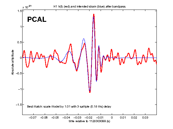
I edited Peter S.'s matlab script to check the sign of these PCAL CBC injections.

Looks like the have the correct sign. See attached plots.

To run code on LHO cluster:
eval '/ligotools/bin/use_ligotools'
matlab -nosplash -nodisplay -r "checksign; exit"

Also in hindsight I should have done a couple CALCS CBC injections just to compare the SNR at the time with the PCAL injections.
gwdetchar-overflow -i H1 -f H1_R -O segments -o overflow --deep 1128303500 1128303651 124
It returns an empty table, so no overflows.
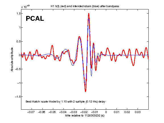
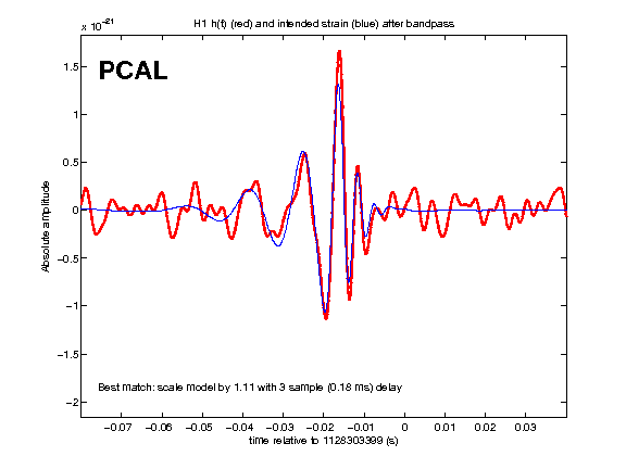
A time-domain check of the recovered strain waveforms is here: https://wiki.ligo.org/Main/HWInjO1CheckSGs. I found that the sign is correct, the amplitude matches within a few percent at most frequencies, and the phases are generally consistent with having a frequency-independent time delay of 3 or 4 samples (about 0.2 ms). Details are on that wiki page.
Thomas Abbot, Chris Buchanan, Chris Biwer

I've taken Thomas/Chris' table of recovered omicron triggers for the PCAL detchar injection and calculated the ratio of expected/recovered SNR and added some comments:

Recovered time      time since                 frequency recovered expected  recovered/expected        comments
                               1128303531 (s)          (Hz)           SNR        SNR           SNR
1128303531.5156	0.515599966	         42.56	34.07	25	            1.3628
1128303534.5078	3.5078001022	        61.90	39.41	25	            1.5764
1128303537.5039	6.5039000511	        64.60	28.29	25	            1.1316
1128303540.5039	9.5039000511	        79.79	23.89	25	            0.9556
1128303543.5039	12.5039000511	1978.42	21.38	25           	0.8552                                  suspicious, the frequency is very high
1128303546.502	15.5020000935	 144.05	26.24	25	           1.0496
1128303549.502	18.5020000935	 185.68	26.38	25	           1.0552
1128303552.502	21.5020000935	 229.34	26.29	25	           1.0516
1128303555.501	24.5009999275	 918.23	27.34	25	           1.0936
1128303558.501	27.5009999275	 315.97	11.05	10	           1.105
1128303564.5005	33.5004999638	 451.89	6.76	          5     	1.352
1128303567.5156	36.515599966	        50.12	68.53	50	          1.3706
1128303570.5078	39.5078001022	 61.90	78.23	50	          1.5646
1128303573.5039	42.5039000511	 76.45	52.04	50	          1.0408
1128303576.5039	45.5039000511	 91.09	48.42	50	          0.9684
1128303579.5039	48.5039000511	 116.63	47.73	50	         0.9546
1128303582.502	51.5020000935	 144.05	52.59	50	         1.0518
1128303585.502	54.5020000935	 177.91	52.3	        50	         1.046
1128303588.502	57.5020000935	 261.81	54.8	       50	          1.096
1128303591.501	60.5009999275	 323.36	55.64	50	          1.1128
1128303594.501	63.5009999275	 414.01	19.67	20	          0.9835
1128303597.501	66.5009999275	 390.25	9.55	       10	        0.955
1128303600.5005	69.5004999638	 481.99	9.34	        10	          0.934
1128303603.5156	72.515599966	         48.35	136.81	100	          1.3681
1128303606.5078	75.5078001022	 71.56	156.91	100	         1.5691
1128303609.5039	78.5039000511	 76.45	102.72	100	         1.0272
1128303612.5039	81.5039000511	 138.03	102.85	100	          1.0285
1128303615.5039	84.5039000511	 134.83	95.52	100	         0.9552
1128303618.502	87.5020000935	 1283.14	104.17	100	         1.0417                 frequency seems a bit high
1128303621.502	90.5020000935	 211.97	107.18	100	         1.0718
1128303624.502	93.5020000935	 261.81	104.53	100	         1.0453
1128303627.501	96.5009999275	 323.36	109.66	100	         1.0966
1128303630.501	99.5009999275	 414.01	42.15	40	        1.05375
1128303633.5005	102.5004999638	 959.39	19.11	20	        0.9555                  this last injection had some kind of glitch on it

In most cases looks like the ratio is within 0.1 of 1. On a quick glance I see 10 injections that were not within this range.


