TITLE: Sep 17 OWL Shift 07:00-15:00UTC (00:00-08:00 PDT), all times posted in UTC
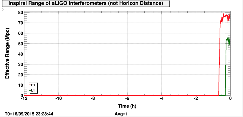
STATE Of H1: Observing at 77 Mpc
SUPPORT: Sheila
SHIFT SUMMARY: After 12+ hours of not locking, we are back in business. I redid the initial alignment followed the printed Initial Alignment Checklist on the desk after the seismic nosie came down to almost nominal because PRMI looked hopeless. LLO is still trying to acquire lock.
INCOMING OPERATOR: Patrick
Activity log:
8:00 Begin initial aligment. Adjusted PR3 to maximize COMM beatnote. Spent 10 minutes at INPUT_ALIGN without luck. Trended IM4 and PR2 back to the last time the ifo was locked. I brought IM4 back to where it was. Touched PR2 YAW to get 00 mode on As Air camera.
8:04 Darkhan left
9:11 Craig left
9:12 BS ISI WD tripped during MICH_DARK_LOCK twice. Requested down and waited until the optic became settled and moved on.
ENGAGE_ASC_PART3 took ~5 minutes.
Guardian stalled at DC_READOUT_TRANSITION (alog21608). OMC was not ready for handoff and was locked at the wrong mode. I called Sheila for help but the ifo lost locked shortly.
10:52 Locked at NOMINAL_LOW_NOISE
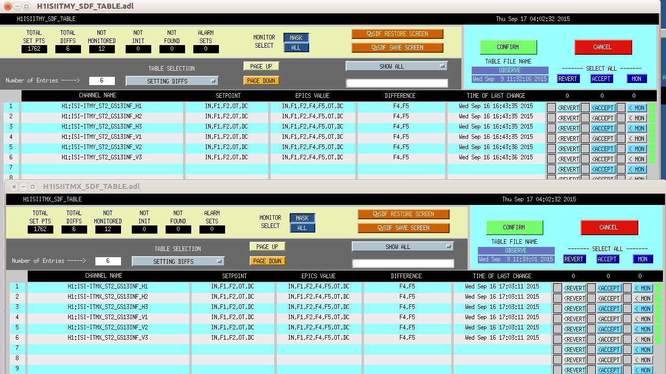
11:13 Back to Observing after I cleared the SDF diff.
13:15 Lockloss. More earthquake....
13:46 Locked at NOMINAL_LOW_NOISE
13:48 Undisturbed.
15:00 Hand off to Patrick.

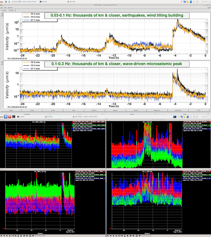


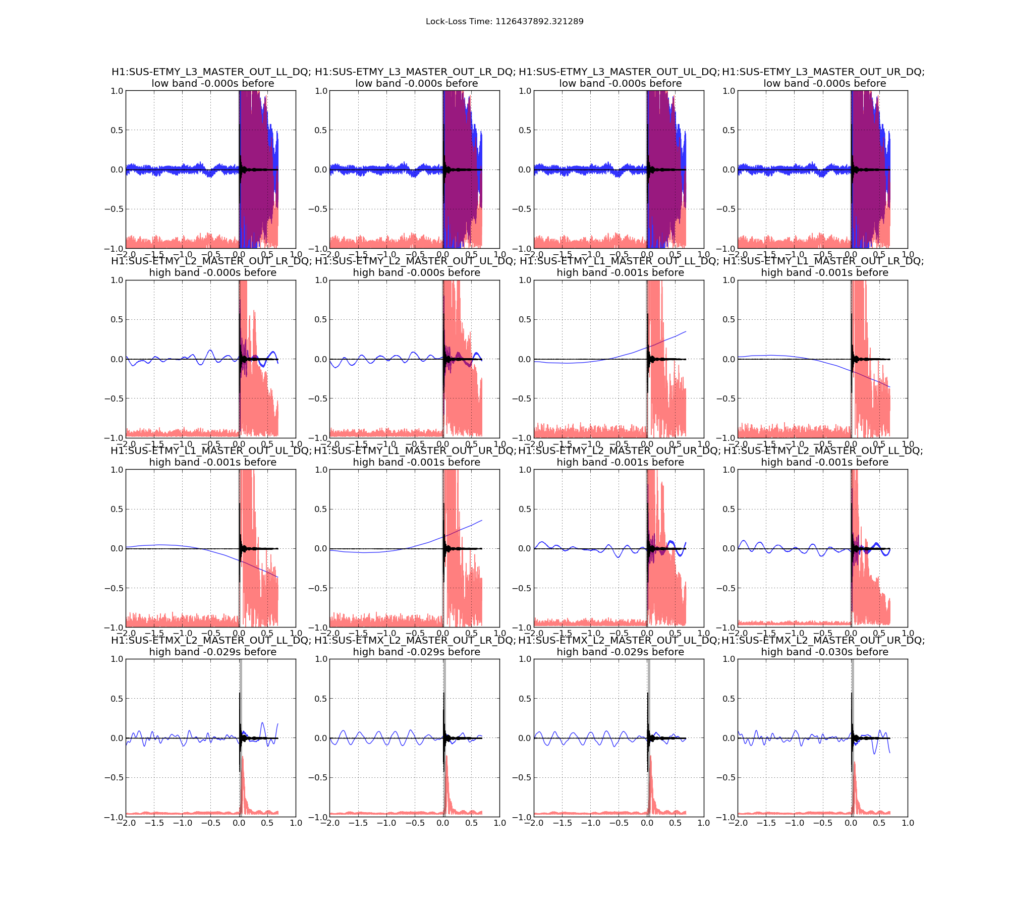

Lockloss 13:15 UTC. I'm not sure if we lost lock due to a single 5.3M earthquake in Chile or two consecutive 5.3M earthquakes that happened just 5 minutes apart from each other. Requested ISC_LOCK to DOWN and waiting for the earthquake to pass....
Observing again at 74Mpc.