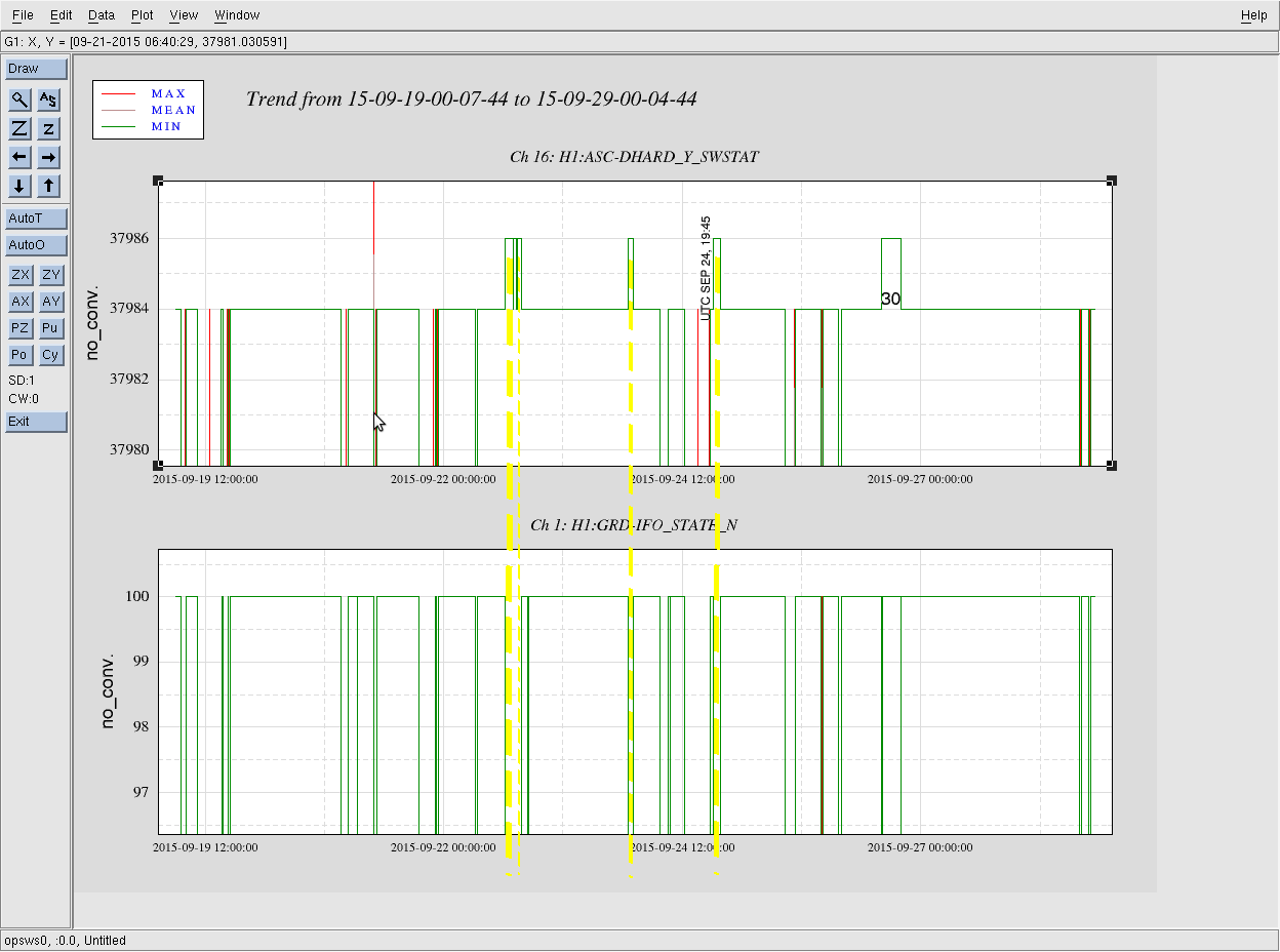
Attached is a snapshot illustrating which observe mode segment had the ASC DHARD Yaw FM2 filter engaged. Recall that the filter was engaged a few times over the last week in an attempt to ride out a species of ground motion. In all but one of the cases when this FM2 filter was engaged, the IFO Observation Intent bit was NOT set. The following is the one segment when the filter was engaged:
H1 Single IFO Segment #30 from https://ldas-jobs.ligo.caltech.edu/~detchar/summary/O1/
(Segment lists are shown via the blue pop-open banners across the bottom of the page - see specifically H1:DMT-ANALYSIS_READY:1)
30 1127313107 1127329701 16594
Laura Nuttall, Marissa
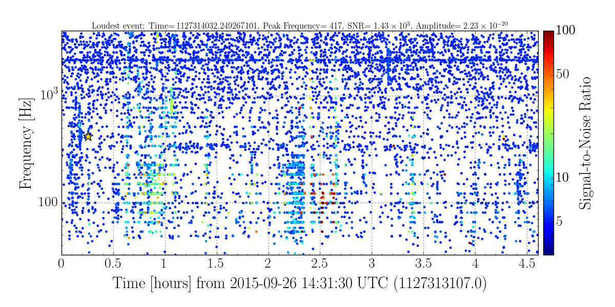
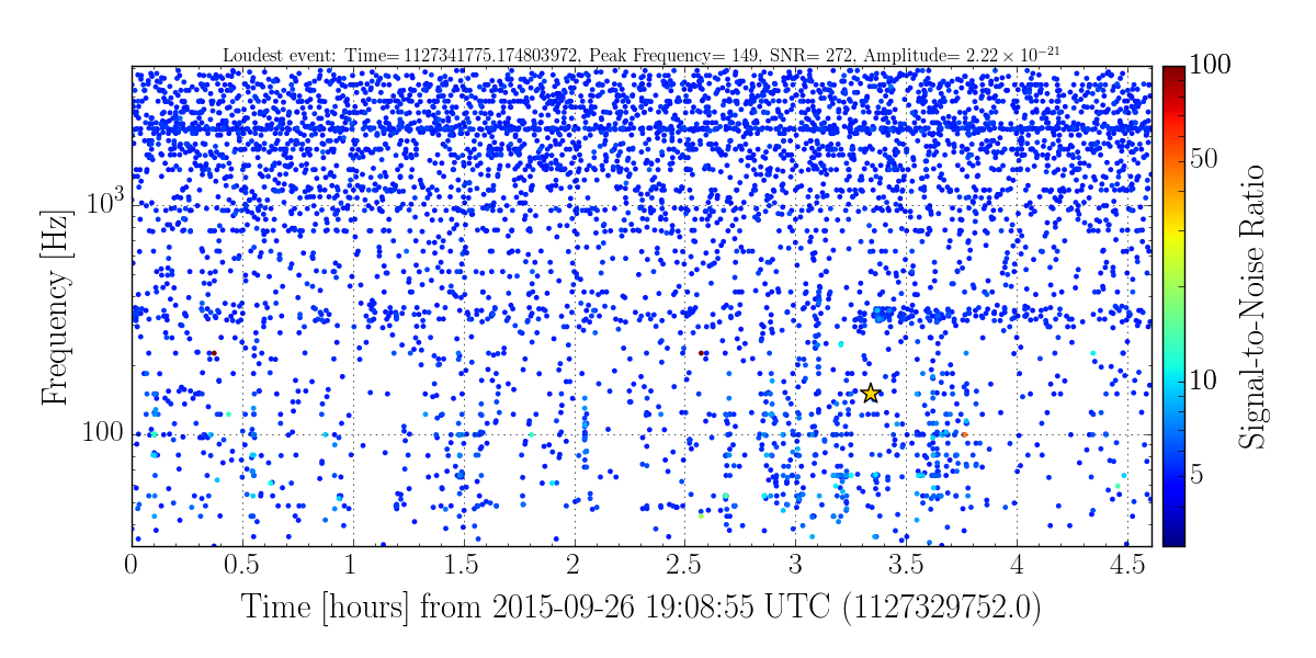
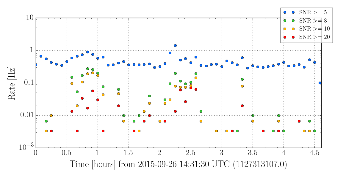
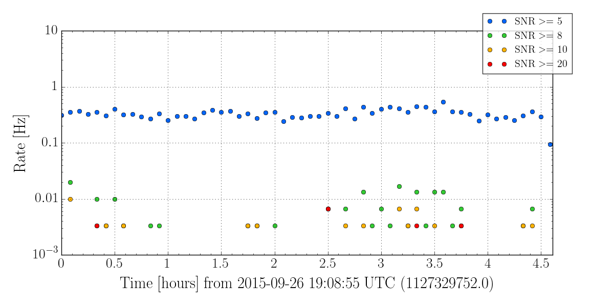
I've repeated what Laura did in alog 21820 for this time, to compare the glitch rate between times that did and did not have the DHARD Y boost and determine whether this should have much of an impact on the transient searches' backgrounds. Unfortunately, this lock segment had some really bad RF45 noise so it's not ideal for evaluating glitch rates (since a lot of this time will be cut out from the search backgrounds), but it's what we have...
I've attached the omicron glitchgrams and trigger rates for the time that the filter was turned on, and for the same amount of time just after it was turned off. The overall rate of low SNR triggers is about the same during both segments, with some times of increased rate of higher SNR triggers while the filter was engaged, most likely due to the RF45 noise. Similarly, the glitchgrams' structures do not appear significantly different between the two segments, besides the awful RF45 times.
From this comparison, I would agree with Laura's earlier conclusion that this filter does not appear to have a significant effect on the background.