Here's a quick summary of the Estimator installation from this week (Edgard, Oli, Jeff K, Brian L)
slides with basic info: T2500082
FRS ticket 32526
Installation alogs
Infrastructure installed on HAM2/PR3 and HAM5/SR3, style updates to model, MEDM linked to sitemap - alog 83906
Tools installed in Estimator folder in the SUS SVN alog 83922
We updated the OSEM 10:0.4 calibration filters, but only on SR3 and PR3. alog 83913
Damping filters installed - alog 83926
Tested the fader switch - alog 83982
Designed and installed a blend for SR3 Yaw (DBL_notch in the first filter bank) - alog 84004
Created a new OSEM calibration script - alog 84005
(Edgard is thinking about a general version of this using Python, that is still TBD)
Fitting is well underway, but isn't done yet.
We made much more progress than we expected - thanks Oli and Jeff for all the help. It's not quite ready to go, we need to install the TF fits for the model.
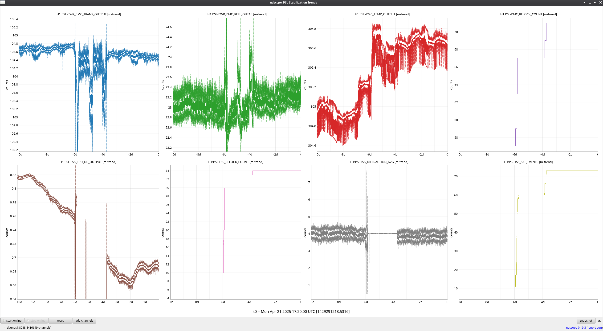
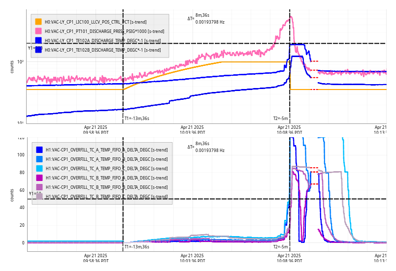
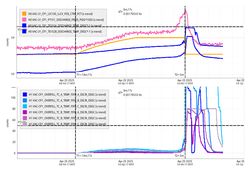
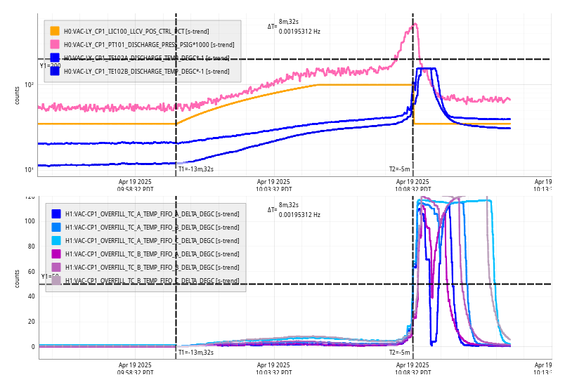
We might have actually been able to test, except the temperature changes from the pumpdown were causing the SR3 optic to move, and the TFs were not very stable. Edgard is working on a log to document this. We have good fits for SR3 yaw taken Friday morning, and we might just try these remotely with Oli's help. We do plan to get a clean set of TFs in a few days when things have stabilized.
-- notes for next steps, thanks to Sheila for this --
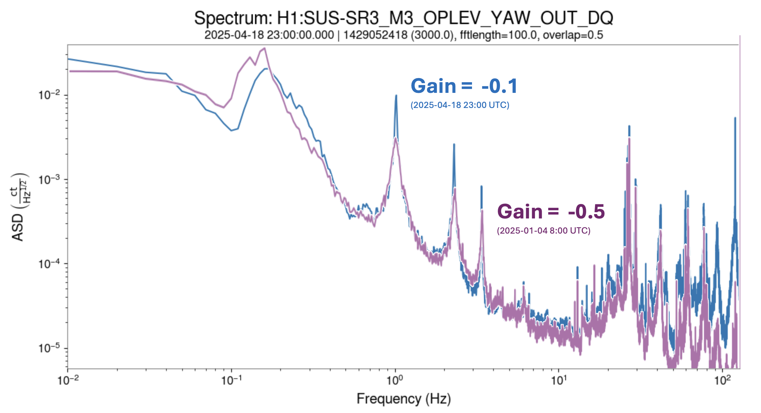
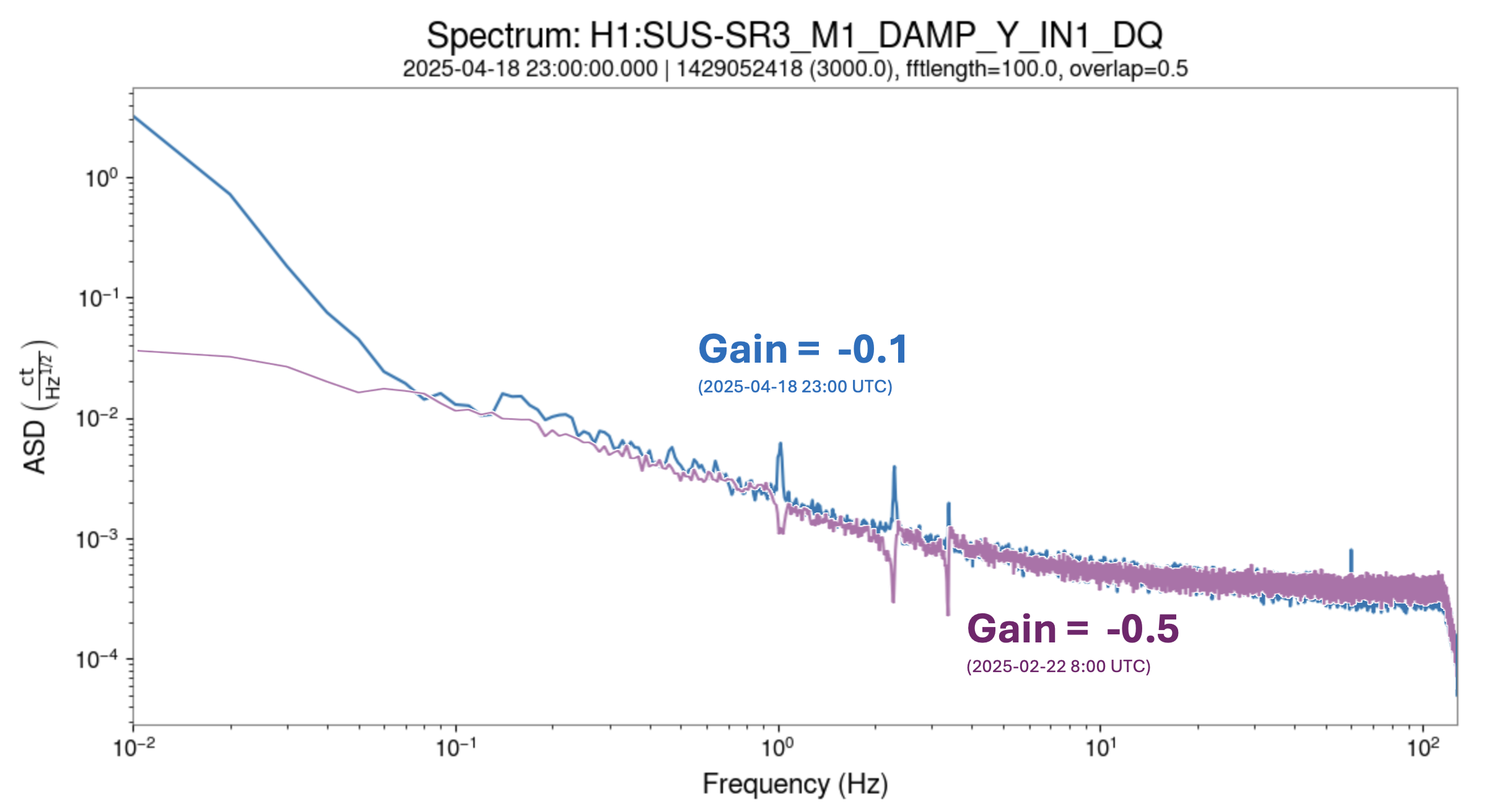
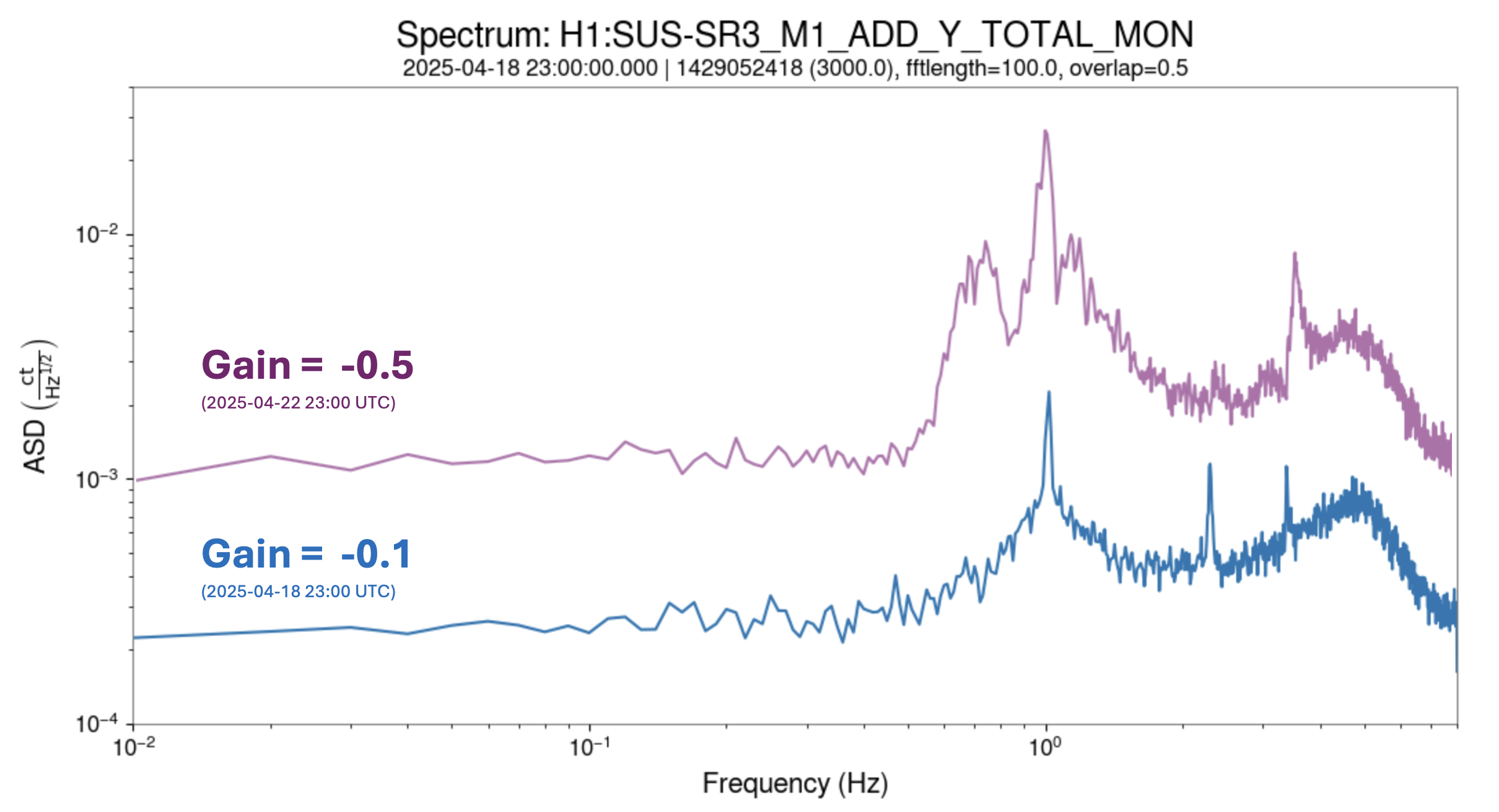
We plan to leave the SR3 overall yaw damping gain at -0.5. This means we'll set the 'light damping' to -0.1 and the gain in the estimator to -0.4. Edgard used -0.1 for the fitting, but he notes that the Q's are pretty high so we may need to revisit this.
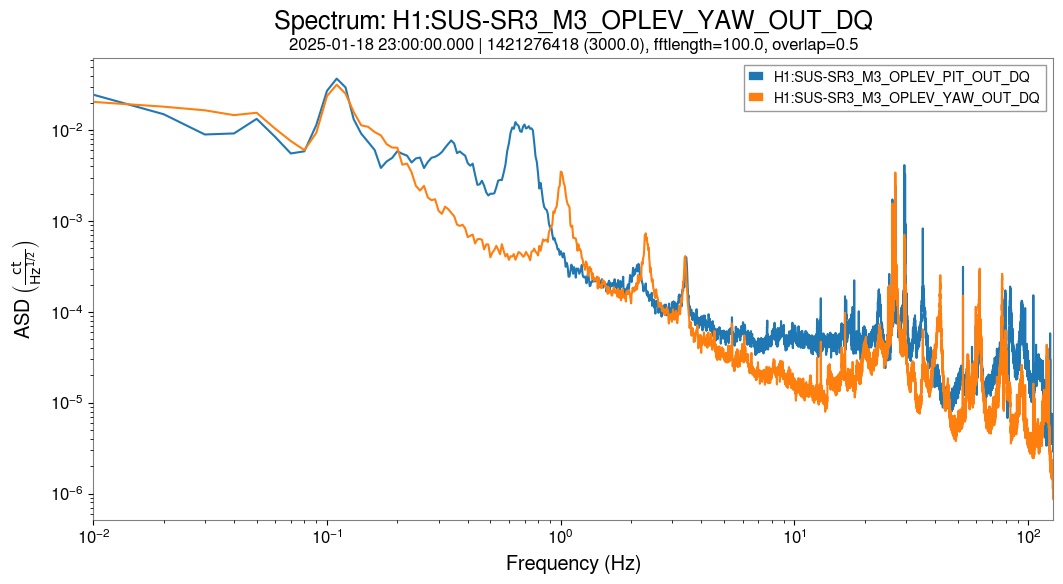
SR3 oplev channels are : H1:SUS-SR3_M3_OPLEV_{PIT,YAW}_OUT_DQ
Some interesting alogs about the impact of changes to SR damping: alog 72106 and 72130
Elenna's PR3 coherence plots: alog 65495