15:00 Pepsi trucks on site
Christina checking out bidgs
15:02 Jeff: Dust Monitor work
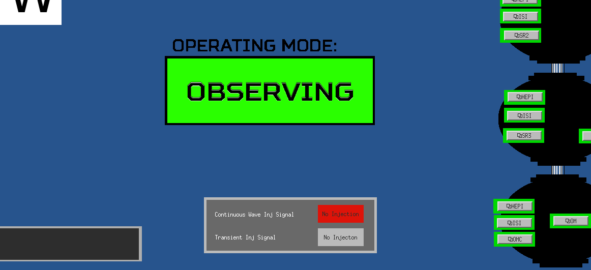
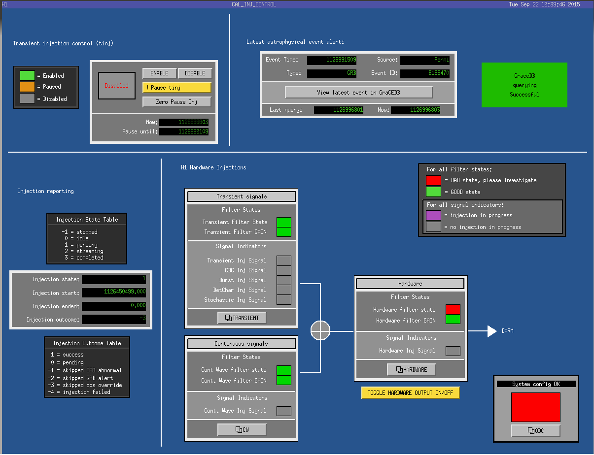
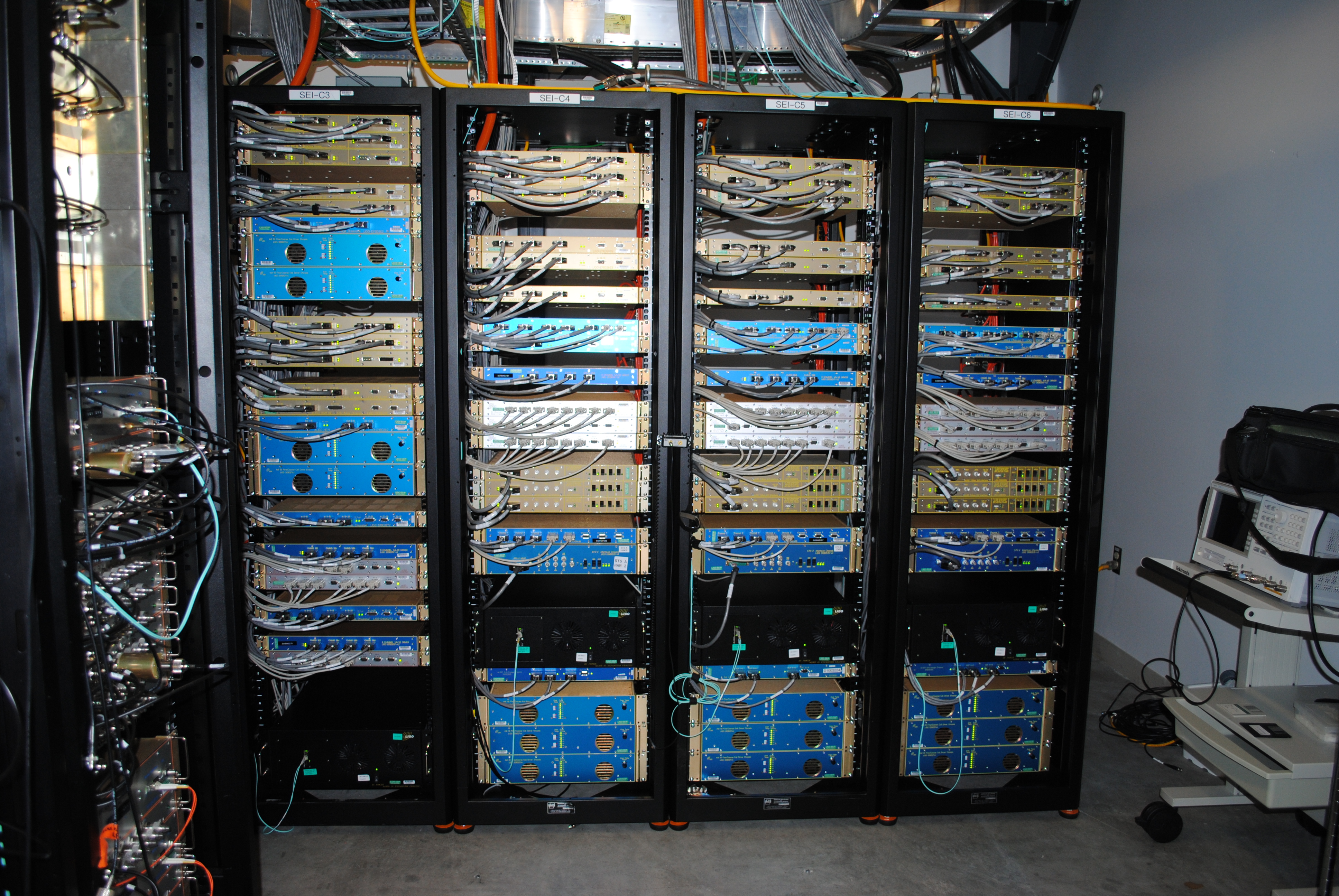
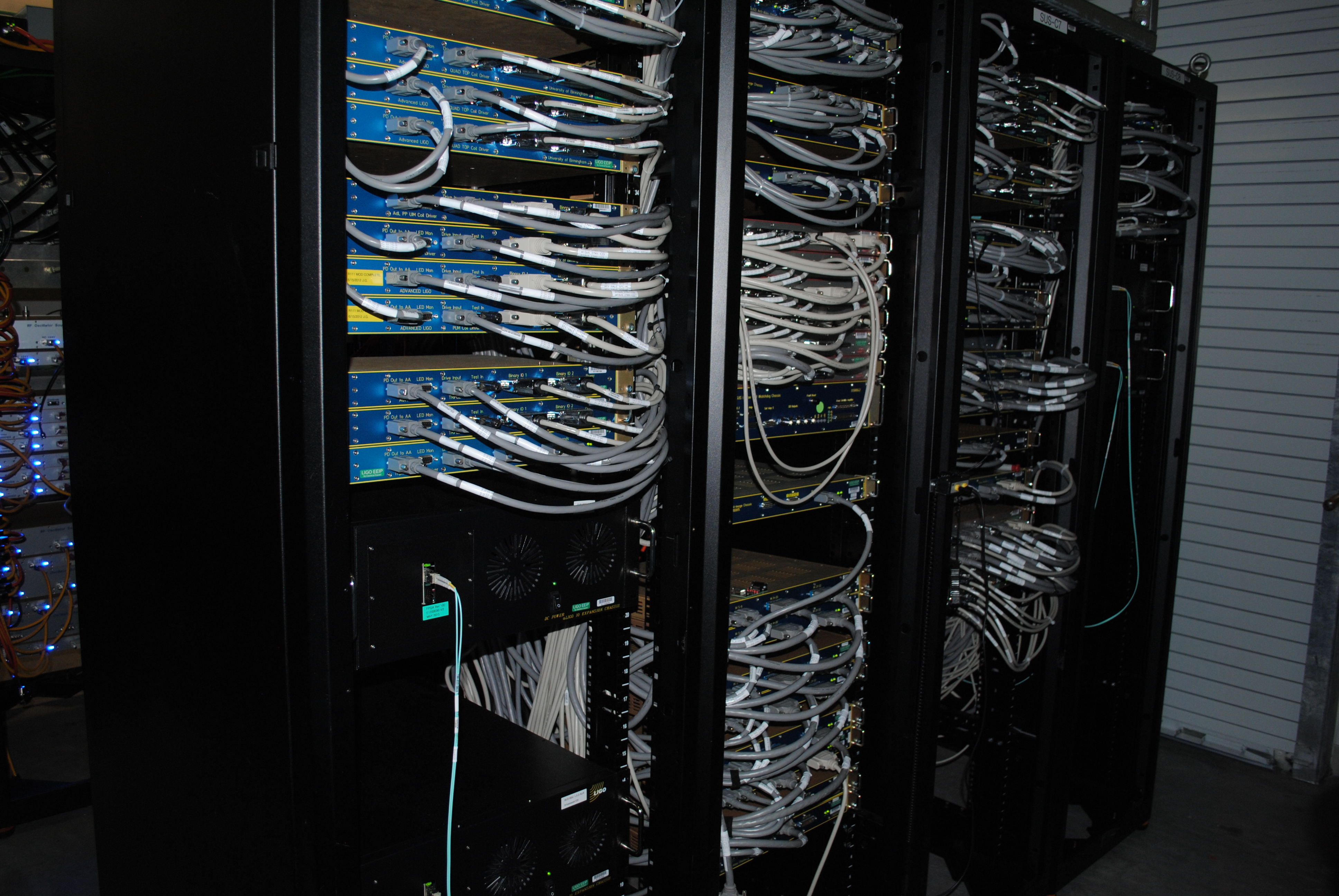
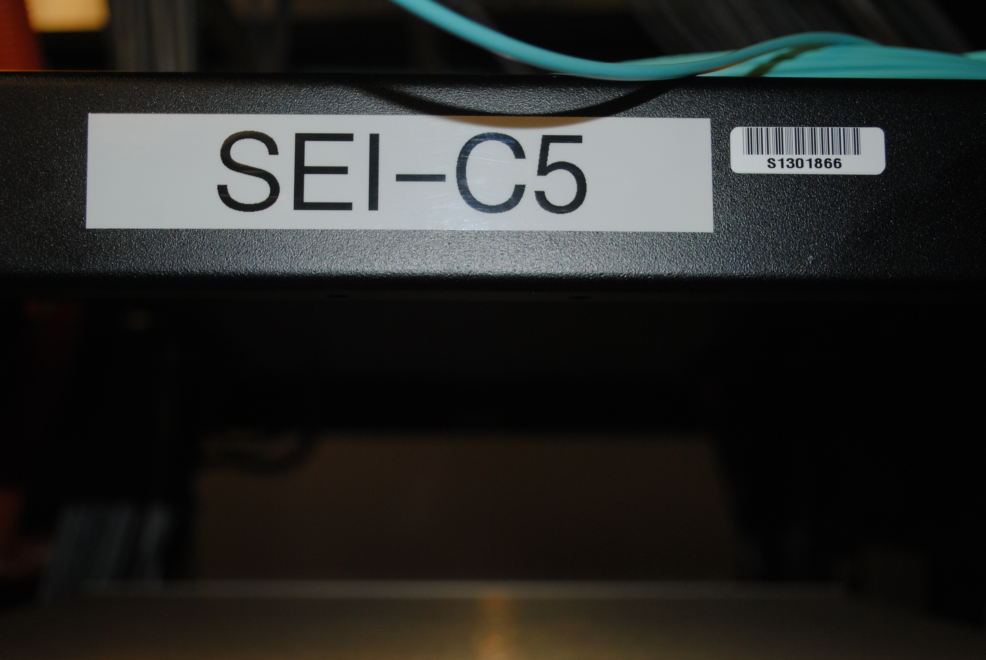
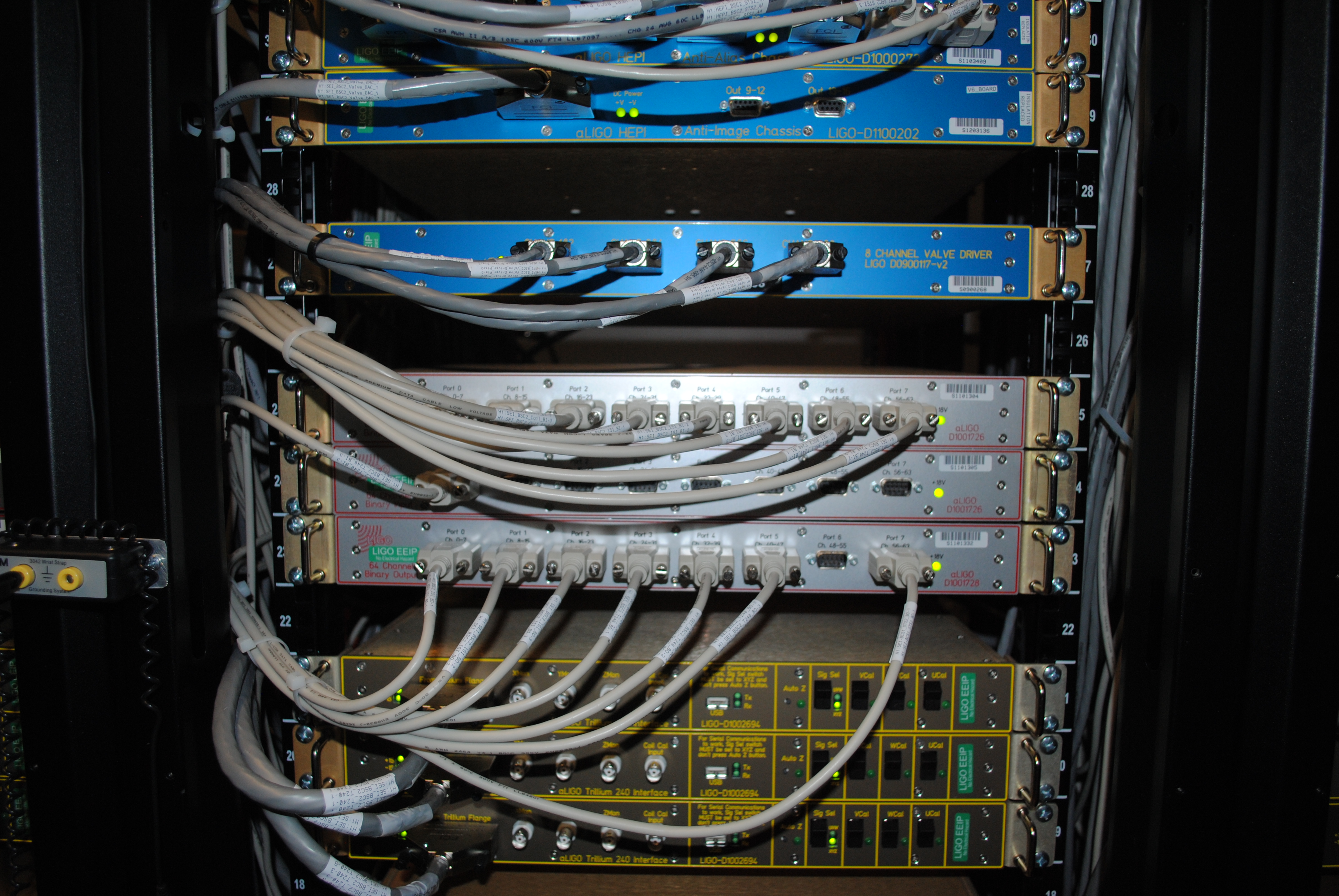
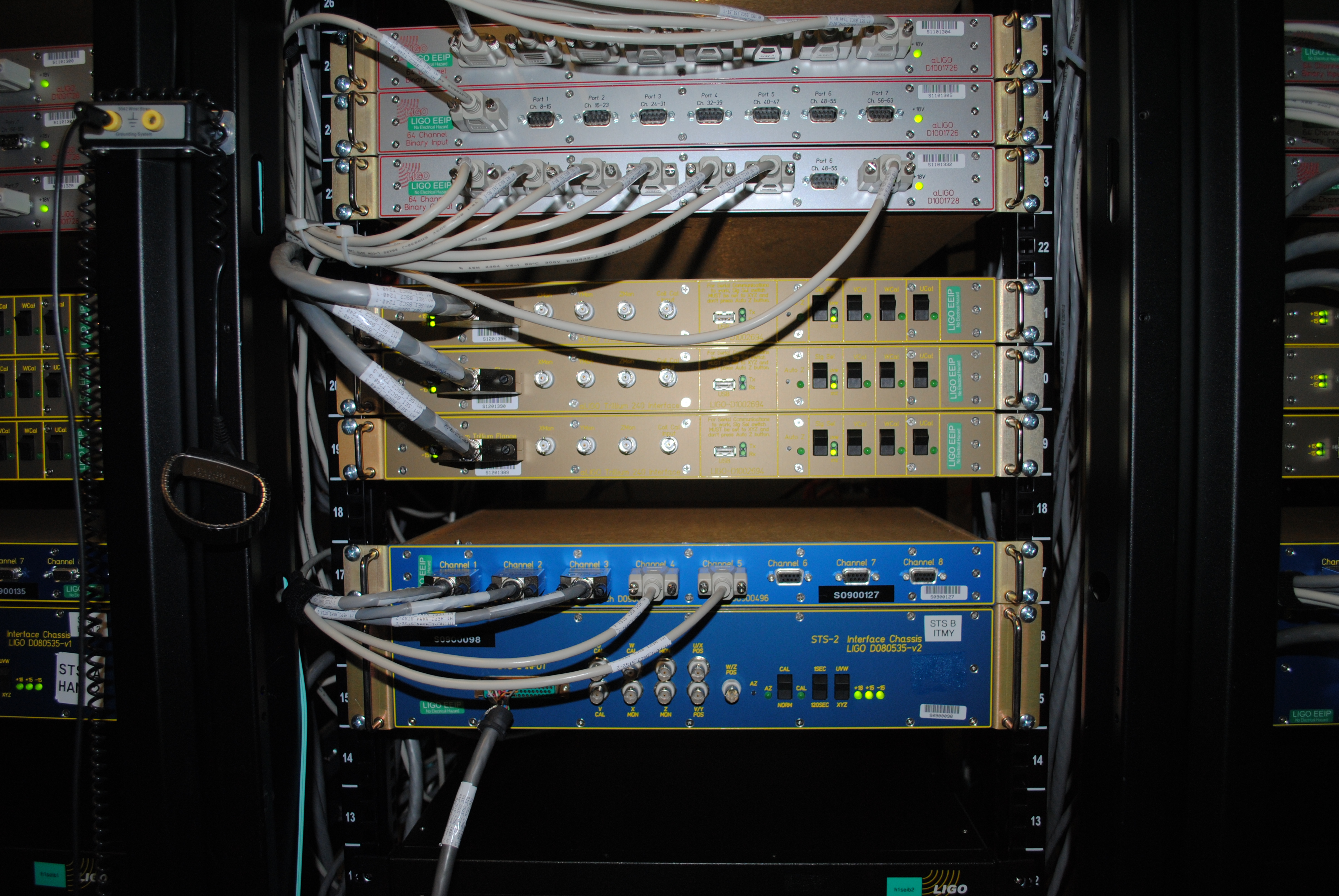
15:35 Fil, Andreas, and Leslie to CER, LVEA to take pictures of the racks.
15:41 Hugh left X end
Patrick to MidY to look for spare Bekhoff
Bubba out of LVEA
15:43 Jodi out of LVEA
15:46 Jeff added 150 mL to PSL chiller
15:49 Jason to Mid X to check on 3IFO Oplev spare
15:51 Praxxair on site - one to EX driving real slow.
Bubba using forklift to move the barricades
16:03 Patrick back
Richard just finished w/ the vault. Heading to Mid X.
Fire department here to test fire hydrant.
Spotted Praxxair at Mid Y. Apparenlt there are two Praxxair trucks.
16:09 Christina + Karen to EX and EY. Just to look. No cleaning.
16:13 Peter to change room to take pictures of the eyewares.
Sheila and Keita checking on Fil at CER.
16:20 Jason out
16:24 Peter done in the change room.
16:27 Richard back
16:39 Mitchell + Hugh checking on 3IFO stuff at North bay
16:42 Karen + Christina leaving EY
Fire department to EY
16:47 Mike + SPIE camera crew out of LVEA
16:50 Richard to EY and MY to pick up Beckhoff stuff
16:51 Bubba to fan room to work on Sf3
16:57 Mike + SPIE crew driving down X arm
17:11 Joe done checking extinguisher (EX, EY, LVEA)
17:14 Richard back
17:18 Mike back
17:19 Daniel pulls some quipment out of electronics room
17:25 Fil to EX
17:32 Daniel out
17:52 Hydrant shut off at corner station
17:53 Jeff B. to mezzanine area
17:54 Jim restart H1 nds0 and nds1
17:44:35-17:55:47 Lots of ETMY saturations
18:05 Kyle starting pumps at MY (leak detection)
18:11 Fil and Andreas at EY
18:12 Cheryl and Ed doing LVEA sweep
18:20 Dave restart broadcaster
18:24 Hugh to both end stations to photograph stuff
18:30 Jeff B. out. And ging to bring up roll up door 3 feet to move in boxes (not heavy).
18:35 Evan and Jenne to LVEA (ISC rack)
18:37 Hugh at EX. Ken drilling hole on the beam tube concrete
18:05:36-18:34:34 Hell of ETMY saturations
18:41 Jeff B. done. He also added water to TCS chiller =D
18:45 Evan and Jenne out
18:46 Fil to EY to pickup stuff.
19:01 Hugh at EX. Fil just left EX.
19:07 Fire guy done checking extinguisher.